
Tekno EB410.2 4WD Buggy Online Build
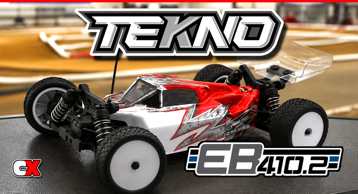
The original EB410 was an instant success, winning races in the hands of both beginner and seasoned drivers. The car was easy to work on and built like a tank, making it a solid performer when others failed.
The car wasn’t perfect though, and soon the tinkerers came out with optional ways to mount things (like the rear shocks). This enhanced the performance of the car, making it an even more fun car to drive.
The cool thing – Tekno was watching. They not only gathered this info, they built the .2 with most of these enhancements right in the box. This is pretty huge, basically giving the customer a perfected iteration of the first gen car.
I’m lucky enough to, once again, get one of these wheelers to build, drive and race! This time, though, I’m not going to be rocking it in the 13.5T class – we’re going right up with the big boys – MODIFIED!
So, tag along as we assemble the EB410.2 in our step-by-step guide.
Tekno RC EB410.2 4WD Buggy Build – Part 1
Tekno’s EB410.2 comes equipped with 3 high-quality fluid-filled gear differentials. The front and rear differentials include steel gears while the center diff uses a thick, plastic spur gear.
Build Notes:
You’ll be using some of the fluids included in the kit – 30K, 15K and 10K – as well as the black grease. Things might be a little messy, so it’s best to keep some clean rags/towels in the vicinity for clean up.
Step 1:
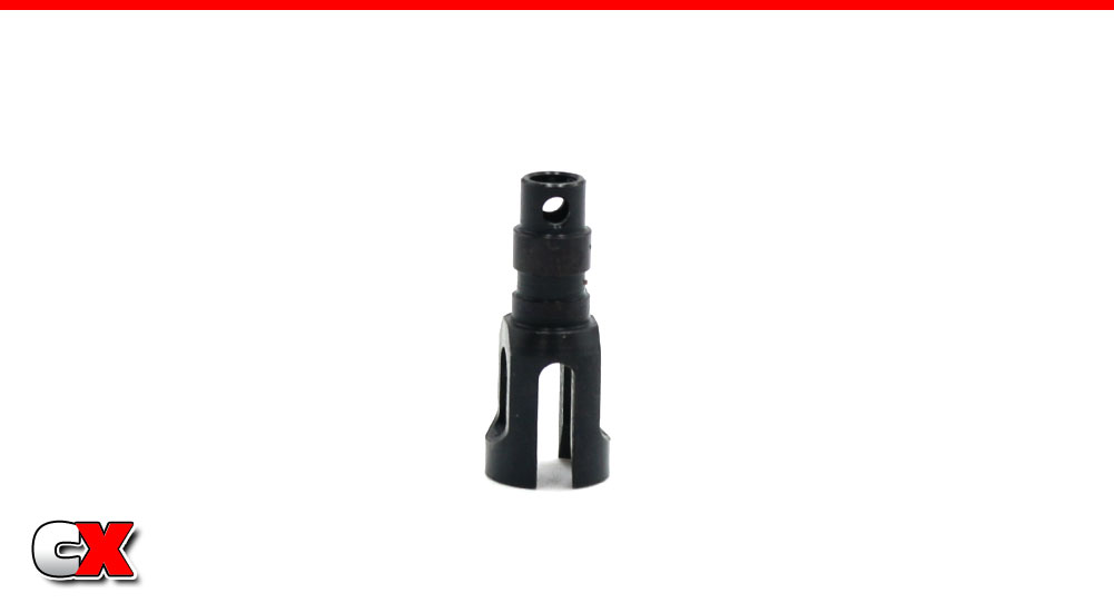
Before we start the build, I always like to point out the orientation of the cross-hole in the outdrive. Notice it is inline with the groove for the CVD pin; you’ll want to make note of this a little further down the build.
Step 2:
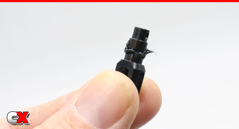
Apply a liberal amount of grease in the groove as shown.
Step 3:
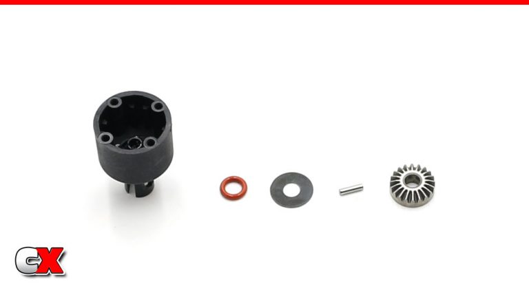
Slip the outdrive into the diff housing. Now install the parts; red o-ring, thin washer and the cross pin. A little extra black grease on the o-ring will help here as well.
You can locate the cross pin hole in the outdrive as we explained in Step 1.
Step 4:
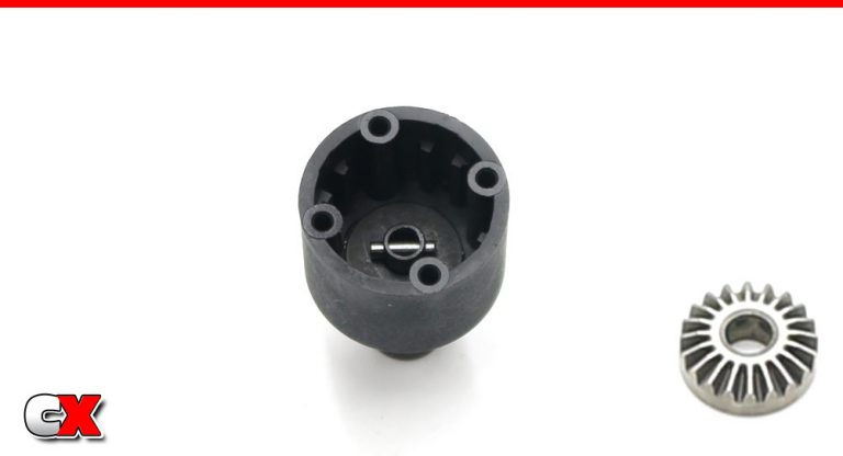
Now drop the sun gear into the diff housing, keying the pin to the grooves in the back.
Step 5:
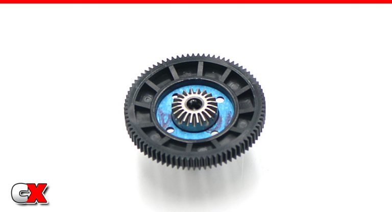
Using the same method, build the spur gear side of the center diff. The only difference is the addition of the gasket.
You can use a light dab of black grease to help keep the gasket in place.
Step 6:
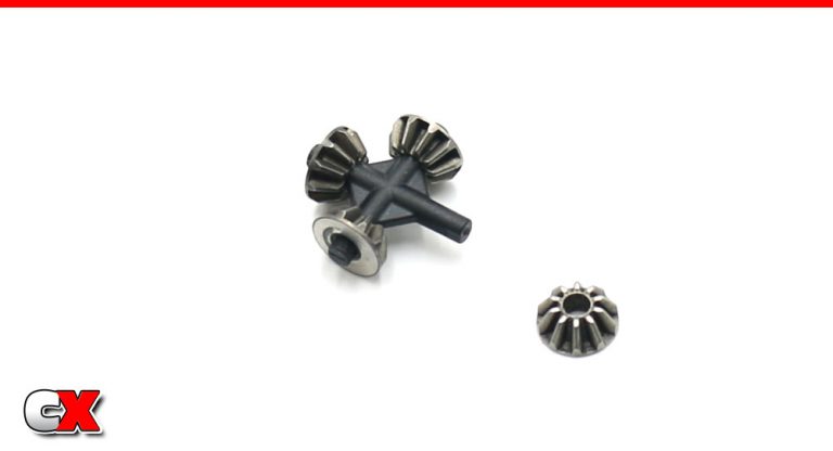
Slide the small sun gears onto the differential cross-pin.
Step 7:
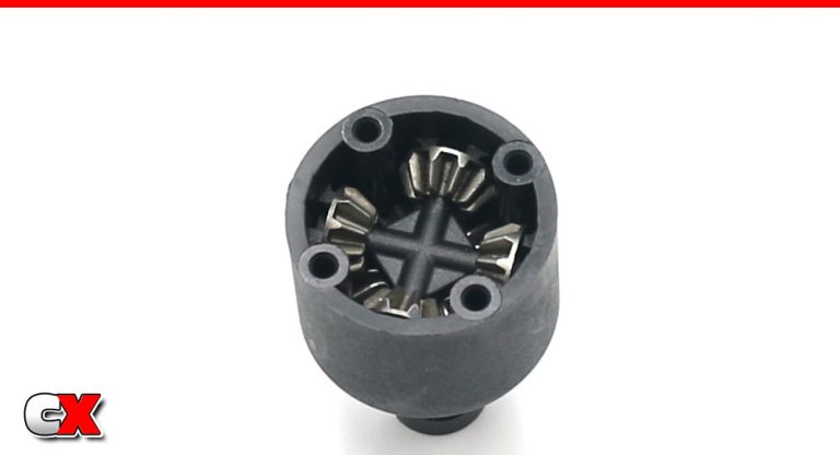
Drop the assembly from Step 6 into the diff housing. While pressing down on the middle of the assembly, rotate the diff outdrive to help seat all the sun gears.
Step 8:
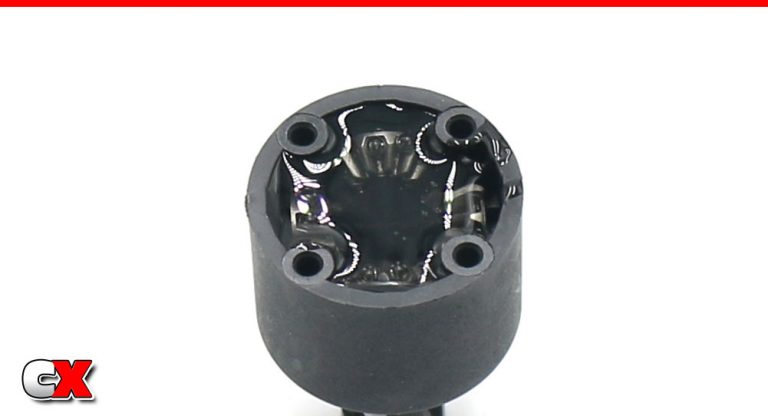
Fill with 30K diff fluid to just past the top of the sun gears. Wait a minute to let the fluid drain into all the nooks and crannies, then refill again to the same point. It may take a few moments since the fluid is quite thick.
Step 9:
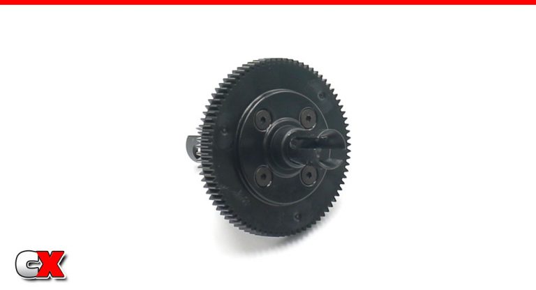
Mate the two diff halves together, pressing firmly to make sure they seat correctly. You may need to rotate the diff outdrives to get the sun gears to mesh. Secure with the 4 M2.5x10mm screws. Do not overtighten; just make sure they are snug.
Step 10:
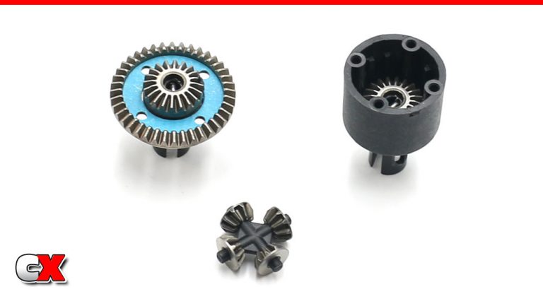
The front and rear diff builds are exactly the same with the exception of the steel ring gears instead of the plastic spur gear. Make sure you build one diff with 15K and the other one with 10K fluid.
Step 11:
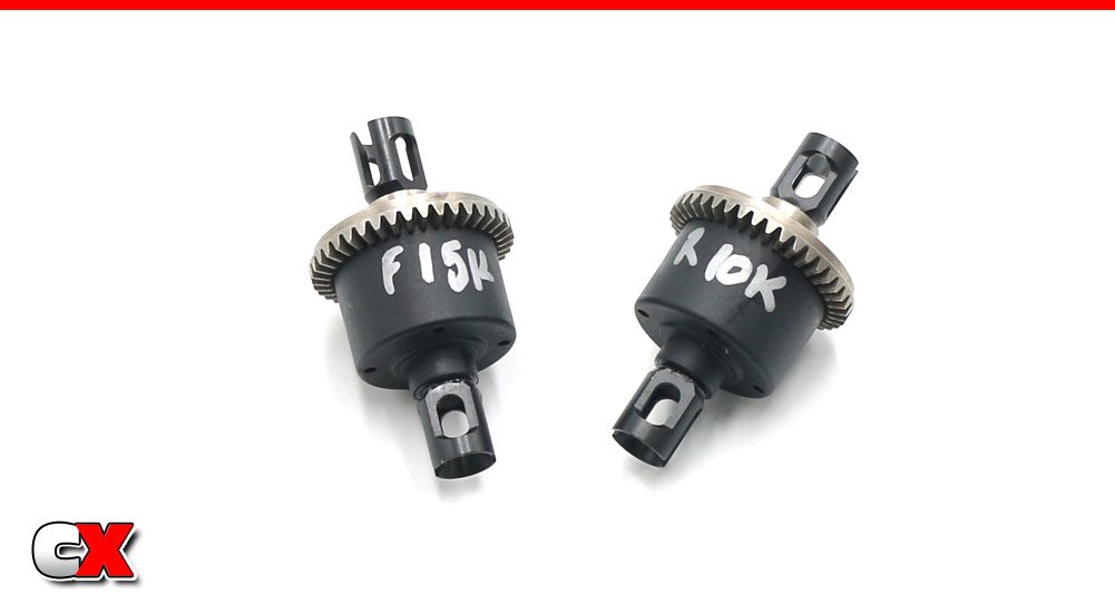
As with all my builds, I like to write on the outside of the diff the fluid inside. This helps me keep track of which diff goes where (front or back) as well as giving me a reference point when it comes time for a rebuild.
Excellent – diffs done! Go ahead and clean up any mess you might have made and let’s get on to the next step!
Tekno RC EB410.2 4WD Buggy Build – Part 2
The steering system on the Tekno EB410.2 is exactly like the .1, using a reversed bellcrank setup that is supposed to give a more consistent steering response (however I’ve never driven a Tekno with a standard steering so it’s hard to compare). It is bearing supported and mounts to the front bulkhead, making installation and maintenance a little bit easier.
Build Notes:
We will be installing screws into metal on this step, so have some threadlocker ready to keep them from backing out.
Step 1:
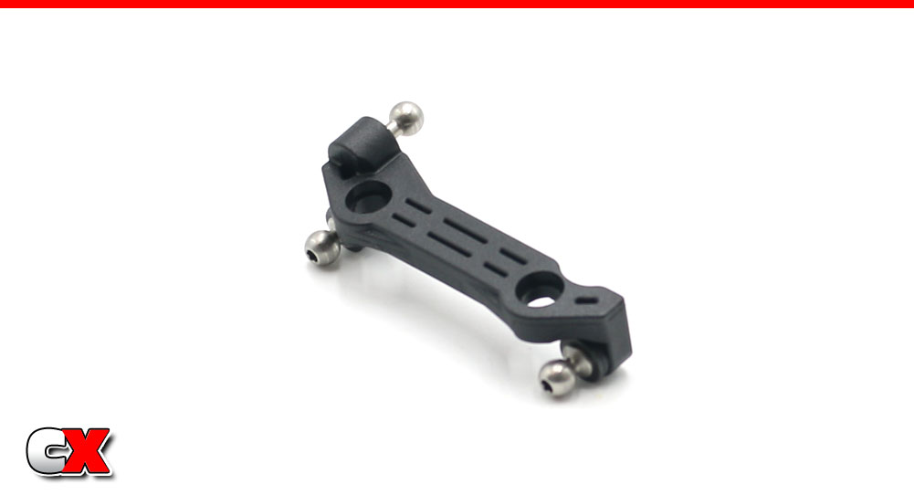
Build the steering rack, using 4 washers behind each ball stud. You can add or remove shims to adjust the Ackermann.
Step 2:
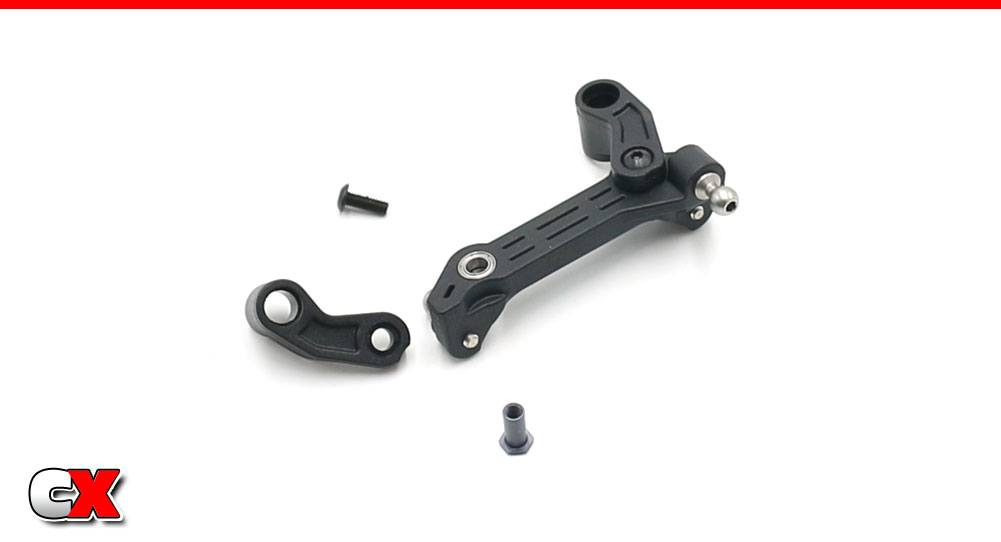
Press the bearings into the rack, then attach the bellcrank arms. Use a small drop of threadlocker to keep the screws in place. Note the direction of the arms. Set this assembly aside.
Step 3:
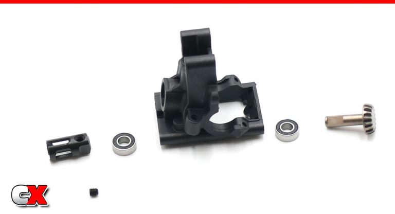
Press the pair of bearings into the front bulkhead. Slide the pinion gear into place, then slip the outdrive over the pinion gear shaft. Secure in place with the M4 grub screw. A drop of threadlocker here is suggested.
Step 4:
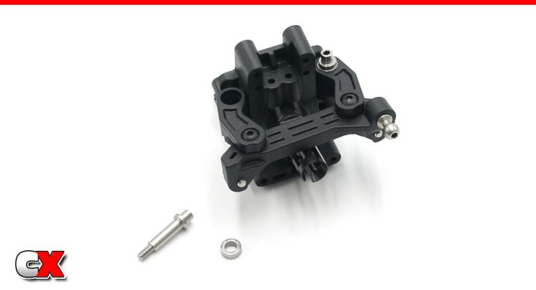
Slowly pre-thread the steering posts into the bulkhead to ensure they go in straight.
Press the bearings into the bellcrank arms, then attach the assembly to the front bulkhead with the steering posts. Make sure the steering system swings freely. If not, back the steering post screws off a tiny bit.
Step 5:
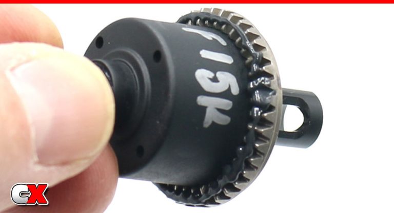
Before inserting the front diff into the bulkhead, apply a liberal amount of black grease to the teeth. This will help prevent wear and quiet the gear mesh down.
Step 6:
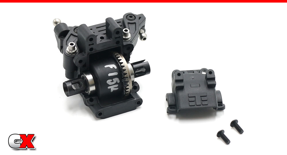
Slip a 10×15 bearing onto each side of your diff and drop it into the front housing. Attach the bulkhead cap using the two M3x8mm screws.
Step 7:
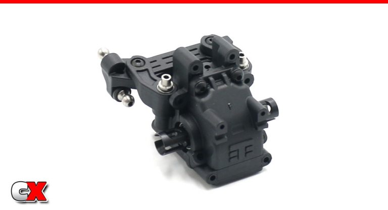
Your front bulkhead should look like this.
Step 8:
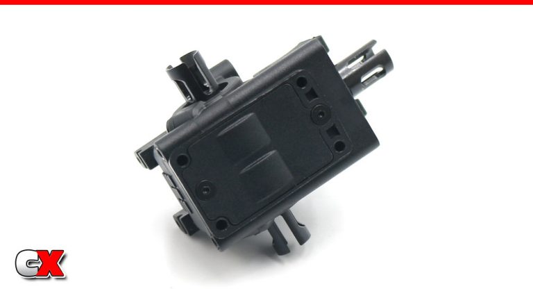
Finish off this step by attaching the cover to the bottom of your bulkhead.
Great job. Your front bulkhead is done – time to move on to the rear one.
Tekno RC EB410.2 4WD Buggy Build – Part 3
The rear bulkhead on the Tekno EB410.2 is very similar to the front, minus the steering. Most of the steps are the same, so we’ll only briefly cover those.
Build Notes:
Since Tekno has moved the rear shocks to the front of the arms, they rear anti-roll bar has to be relocated. The bar (and mounting system) will attach to either side of the rear bulkhead, so make sure you mount it to the CORRECT side during the build.
Step 1:
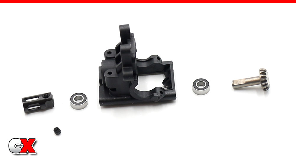
Press the pair of bearings into the front bulkhead. Slide the pinion gear into place, then slip the outdrive over the pinion gear shaft. Secure in place with the M4 grub screw. A drop of threadlocker here is suggested.
Step 2:
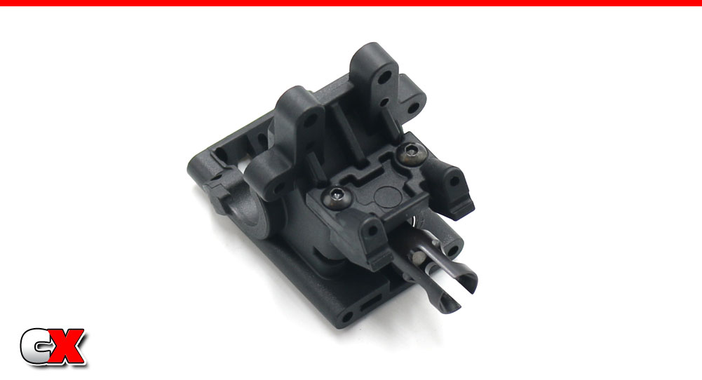
Attach the anti-roll bar mount to the bulkhead. Note the orientation.
Step 3:
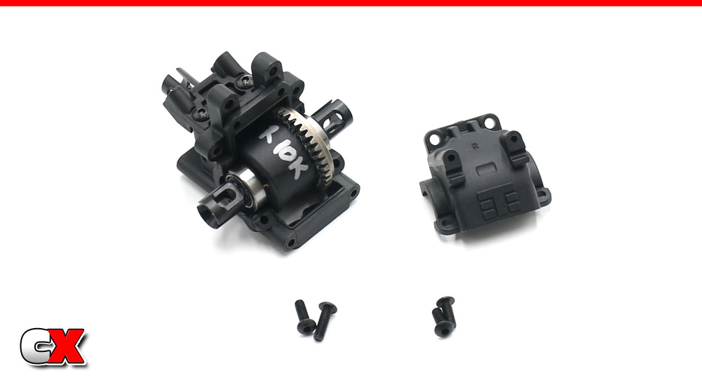
Add a liberal amount of black grease to the rear diff gear. Slip 2 10×15 bearings onto the diff, then drop it into the rear bulkhead. Attach the bulkhead cap. Do not overtighten the lower screws – tighten down, then back off about 1/4 turn. Make sure the diff spins freely.
Step 4:
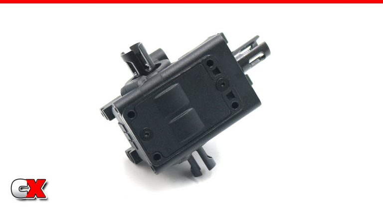
Attach the bottom bulkhead plate.
Step 5:
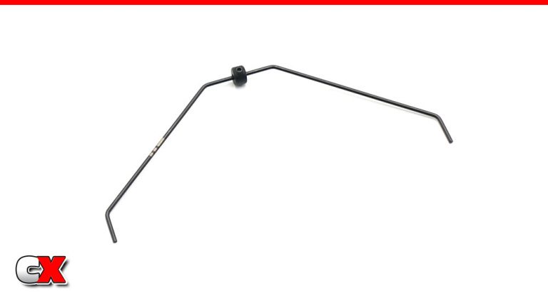
Attach the stopper to the rear anti-roll bar. Do not overtighten the grub screw.
Step 6:
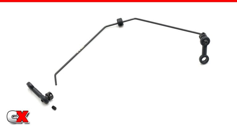
Assemble the anti-roll bar ends. Line the ball ends with the end of the bar, then secure with the grub screw. A light drop of threadlocker is suggested here.
Step 7:
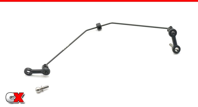
Pop the threaded ball ends into place. Note the orientation.
Step 8:
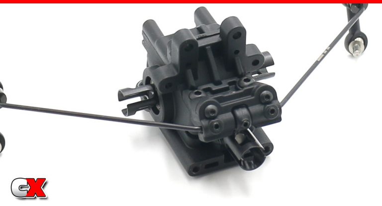
Set the anti-roll bar in place and capture with the mount. Make sure the stopper on the bar fits in the groove.
Thread the grub screws in until they touch the anti-roll bar, then back off slightly. You want the bar to move freely without being hindered by the screws.
And now your rear bulkhead is done. Keep this handy as we’re about to work on the rear suspension.
Tekno RC EB410.2 4WD Buggy Build – Part 4
The rear suspension on the Tekno EB410.2 is similar to the .1; beefy arms, anti-roll bar, aluminum arm mounts with press-in plastic pills, etc. The biggest difference is that the shocks are now mounted to the front side of the arms. This also means the anti-roll bar has to be re-located as well.
Build Notes:
The EB410.2 uses inserts for the hub camber links. They can install in multiple ways; arrows up/arrows down and holes inside or holes outside. Pay close attention to this during the step.
There are also multiple mounting options for the rear hub hinge pin; up, center or down. Pay close attention to this step as well.
Step 1:
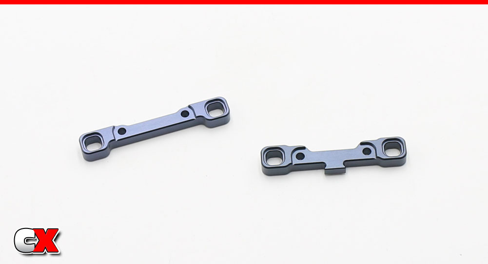
The EB410.2 comes with aluminum arm mounts. Here are the C and D mounts (C on the right, D on the left). You can also see the recesses for the pills.
Step 2:
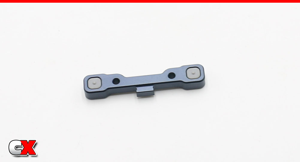
Press a pair of 0° pills into the C mount…
Step 3:
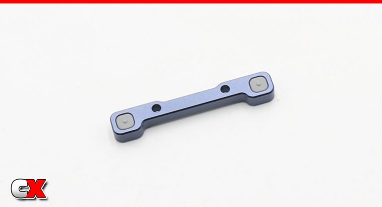
…as well as a pair of 0° pills in the D mount.
Step 4:
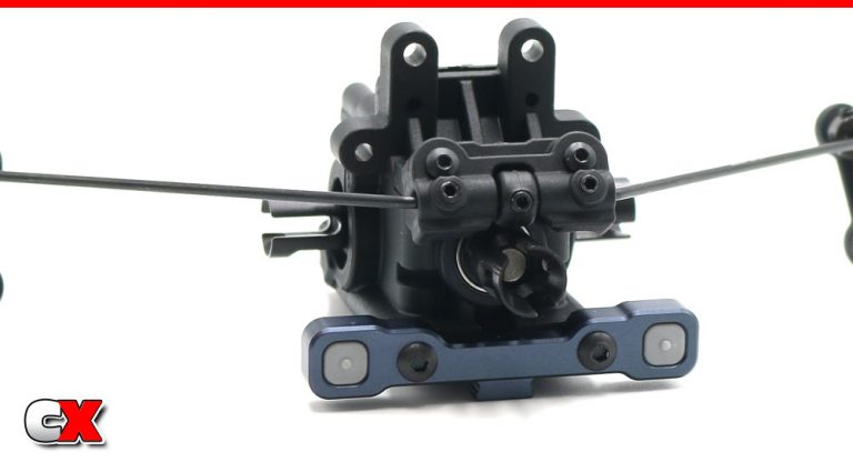
Attach the C mount to the rear bulkhead.
Step 5:
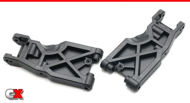
Insert the droop screws into the suspension arms. Don’t worry about how much to screw in just yet; we can set that at the end.
Step 6:
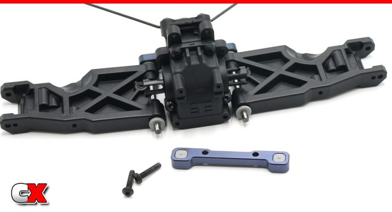
Slide the hinge pins into place followed by the 1mm shim (thicker shim), suspension arm and the .5mm shims (thinner shims, x2 on each side). Pay close attention to the orientation of the parts.
Align the hinge pins with rear D block and secure with the M3x14mm screws.
Step 7:
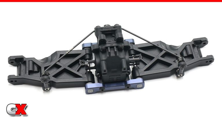
Your assembly should look like this.
Make sure the suspension arms move up and down freely.
Now attach the lower anti-roll bar points to the arms.
Step 8:
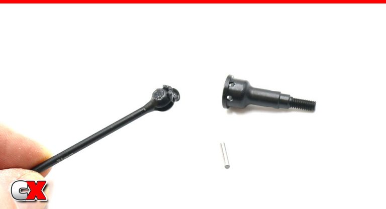
CVD time. Start by inserting the barrel into the bone, then add a liberal amount of black grease as shown. Mate the axle to the bone and slip the pin through to connect it all together.
Step 9:
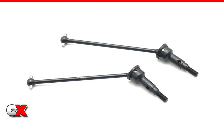
Build 2.
Step 10:
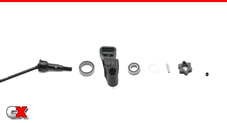
Assemble the rear hubs. Press a 6×12 bearing into the front of the hub, a 10×15 into the rear.
Feed the CVD through the hub, then slip the 2mm shim onto the axle followed by the axle pin and hex. Secure with the grub screw. A small amount of threadlocker is suggested here.
Step 11:
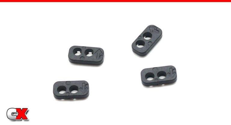
Here’s a look at the camber link inserts. You can see the arrows up and down, holes in or out.
Step 12:
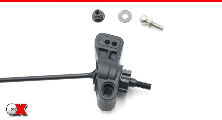
Press a pair of arrow down/holes out into the rear hubs. We’ll be inserting the camber link ball stud into the outer hole.
Step 13:
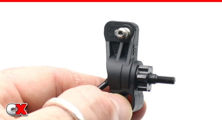
Here’s a closer look at the assembly.
Step 14:
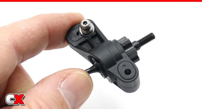
Press the hinge pin mount into place; hole down.
Step 15:
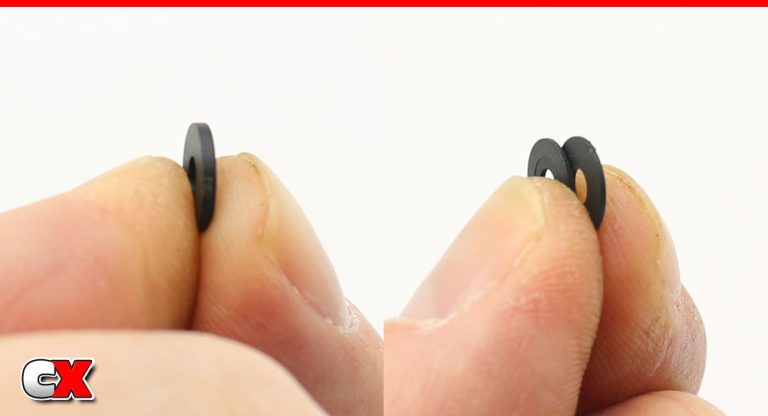
The rear hub spacers (for wheelbase) come in two sizes; thick and thin. Pic for size comparison. Nice fingers.
Step 16:
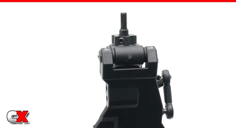
Attach the rear hub to the rear suspension arm. The 2 thin shims should be towards the back of the car.
Step 17:
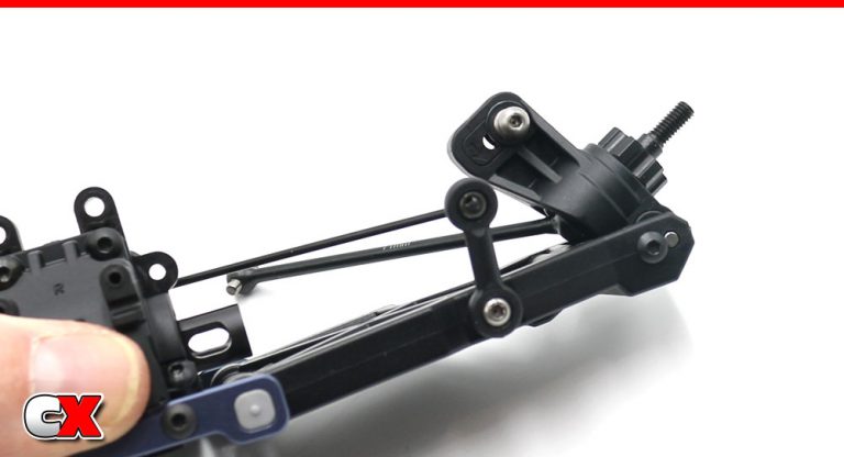
Capture the hinge pin with the M3x4mm screw.
Step 18:
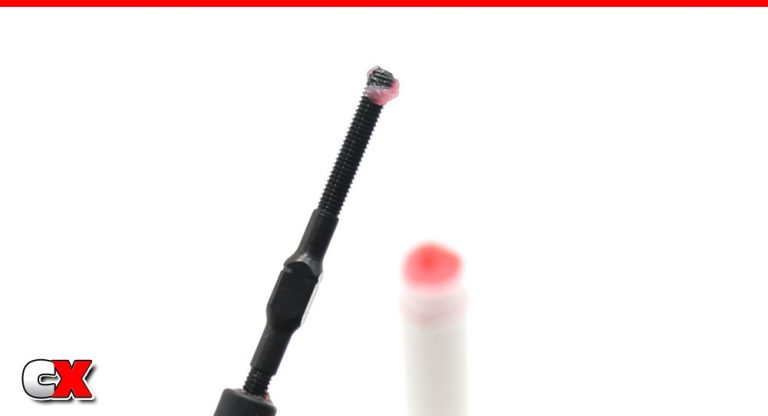
Build the rear turnbuckles.
I like to use Chapstick on the threads to help lubricate when building. This also helps when adjusting the turnbuckles during tuning.
I used strawberry Chapstick so it keeps my car smelling fresh.
Step 19:
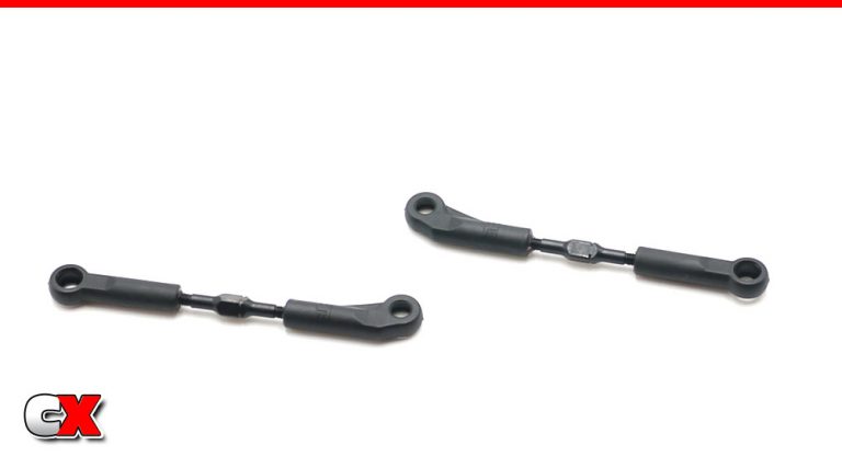
Your turnbuckles – note the orientation of the Tekno ‘T’ on the ball ends. 28.5mm is a good starting point.
And yes, the pictures in the manual do not match. Use the ball cups shown here.
Step 20:
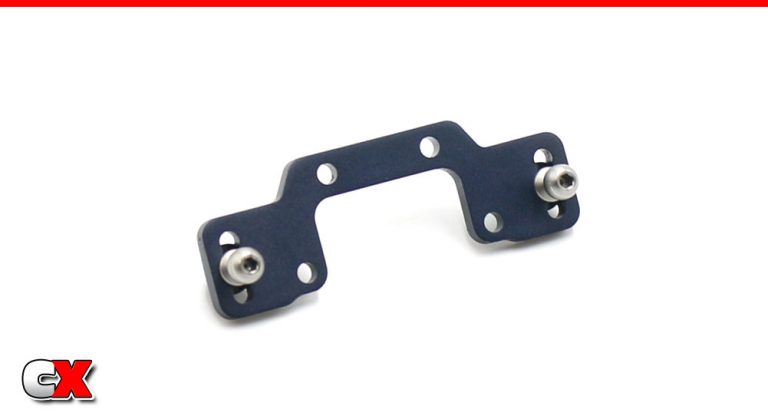
Build the rear camber link plate.
Step 21:
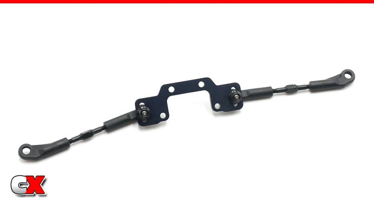
Attach the turnbuckles to the camber link plate, making sure the outer ball cups are swept up.
Step 22:
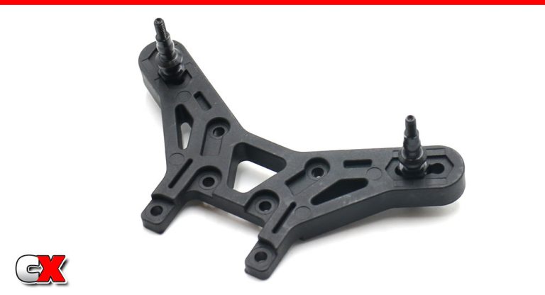
Attach the upper shock mounts to the shock tower. Note the orientation of the tower.
Step 23:
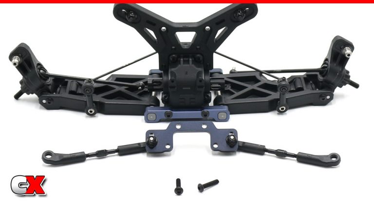
Press the shock tower into place on the rear bulkhead followed by the rear camber plate (note orientation of the plate). Secure with the M3x14mm screws.
Step 24:
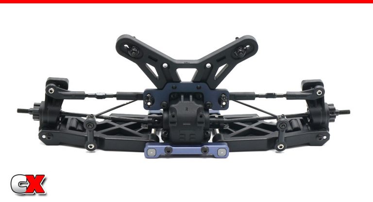
Mate the CVD bone to the differential outdrive, then pop the ball cups into place.
Step 25:
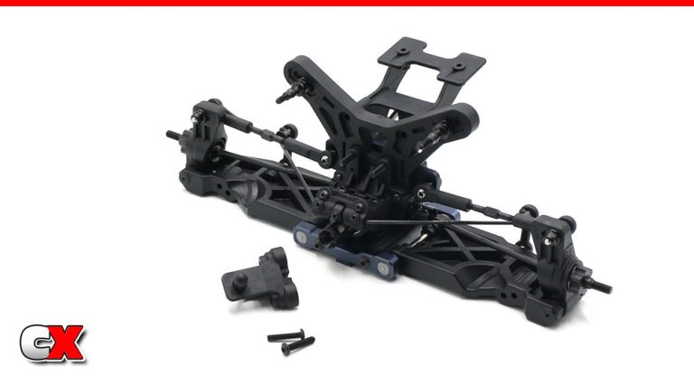
Assemble the rear wing mount and rear body mount to the rear shock tower.
Step 26:
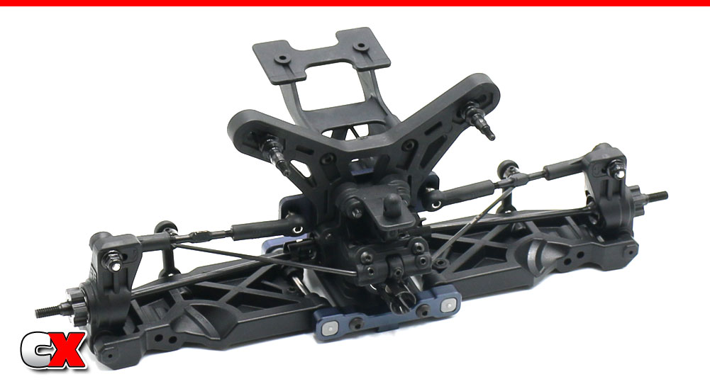
Your completed rear clip should look like this!
Would you look at that – the back end of the EB410.2 is looking good!
Tekno RC EB410.2 4WD Buggy Build – Part 5
The front suspension build on the Tekno EB410.2 is very similar to the rear; anti-roll bar, aluminum arm mounts will plastic pills, etc. We will also be installing the caster and steering blocks as well as the shock tower.
Build Notes:
When building and installing the turnbuckles, always make sure the notches (on the turnbuckles) are facing the same way. The standard direction is to the car’s left.
The turnbuckle ballcups are directional so when installing, make sure the Tekno “T” is facing up.
Step 1:
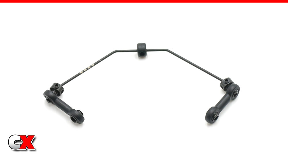
The front anti-roll bar build just like the rear; plastic stopper, aluminum ball ends and plastic links. The only difference is the addition of the aluminum balls instead of the ball ends on the bottom part of the links. Your completed front anti-roll bar should look like this.
Step 2:
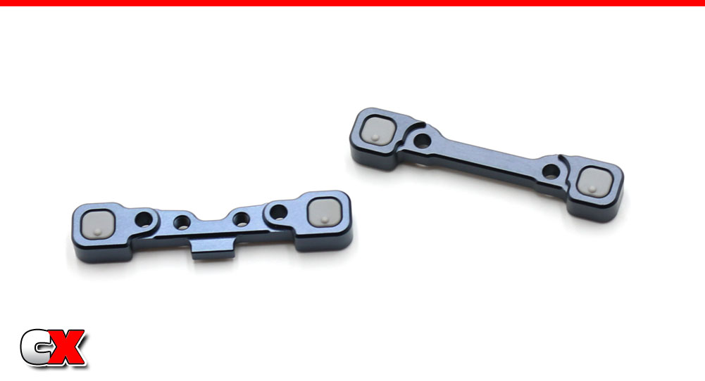
A (left) and B (right) aluminum arm mounts. Press the center-pip-down pills into each block as shown.
Step 3:
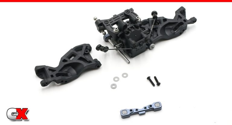
Attach the front anti-roll bar to the front bulkhead. Installation is exactly like the rear in regards to the small grub screws; do not overtighten. Make sure the anti-roll bar swings freely.
Insert the droop screws into the front suspension arms. Don’t worry about making them perfect right now; we’ll set them at the end of the build.
Attach the B arm mount to the back of the front bulkhead. Slip the hinge pin in place followed by the suspension arms. Slide the 3 spacers (1 1mm, 2 .5mm) onto the arm, then capture with the A arm mount. Use the M3x14mm screws to hold it all in place.
Move the suspension arms up and down to make sure they swing freely.
Step 4:
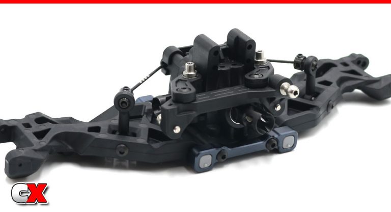
Attach the lower part of the front anti-roll bars.
Step 5:
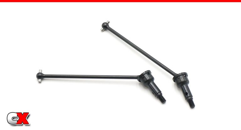
Build a pair of front CVDs. They build exactly like the rears.
Step 6:
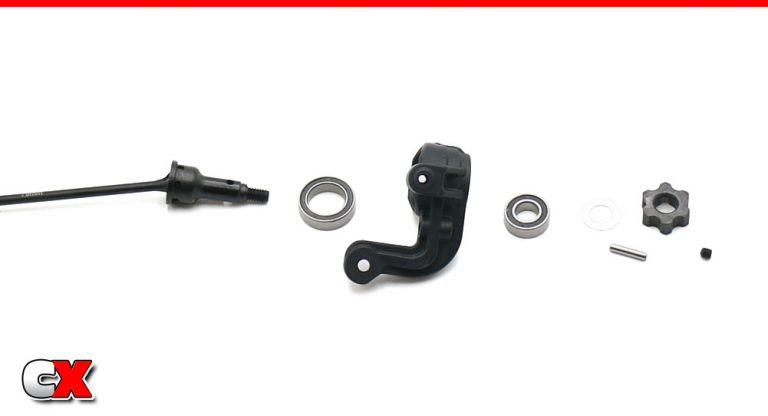
Press the 10×15 bearing into the rear part of the steering knuckle, the 6×12 bearing into the front. Feed the CVD assembly through the bearings, then slide the 6×10 washer into place. Slip the pin through the hole in the axle, then slide the wheel hex adapter into place, keying it to the pin. The grub screw holds everything in place.
Build a right and left side.
Step 7:
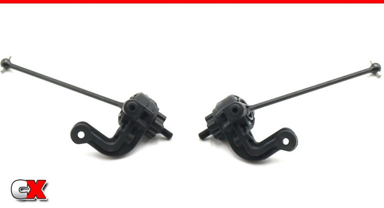
Your completed right and left side steering assemblies.
Step 8:
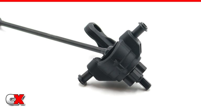
To make sure everything lines up correctly during the next steps, Tekno wants you to pre-thread the kingpin screws into the steering assembly. So, yeah, I did it.
Step 9:
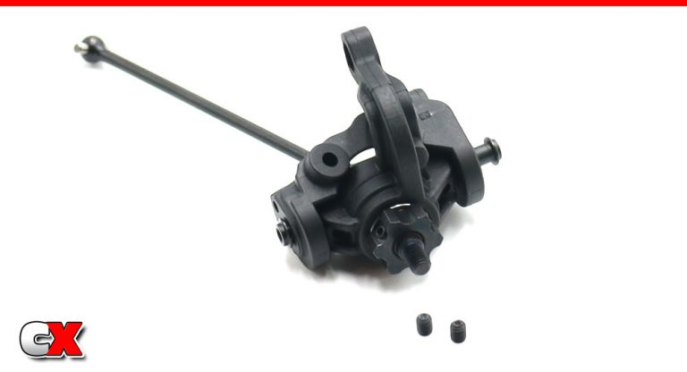
Back those screws out, slide the steering assembly into the appropriate caster block, and re-install the kingpin screws. The two little grub screws are a secondary security blanket to keep the kingpin screws from backing out. DO NOT OVERTIGHTEN – they only need to be snug.
Step 10:
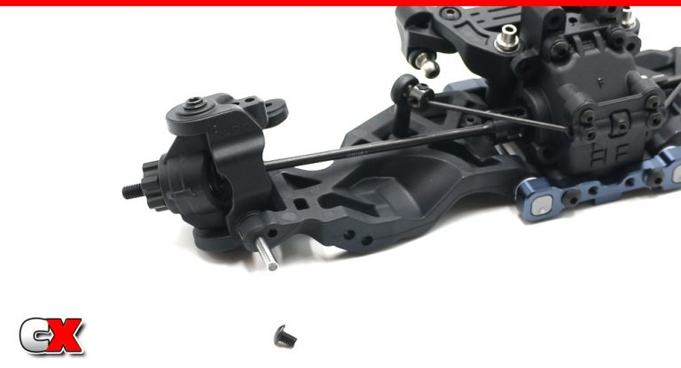
Place the right side steering assembly into place in the right suspension arm, then slide the hingepin through to keep everything in place. Add the M3x4mm screw to secure the hingepin.
Follow the same procedure for the left side.
Step 11:
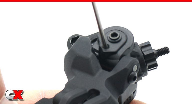
Install the grub screw through the bottom of the caster block. This only needs to be snug.
Step 12:
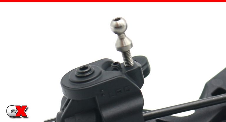
Since the camber link holes in the caster block are so close, Tekno uses a grub screw in the unused hole to help prevent the plastic from deforming.
I like to thread the ballstud in a bit, then fully install the grub screw (until it’s flush with the top of the plastic. Finish installing the ballstud.
Step 13:
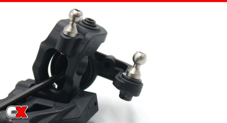
Attach the steering link ballstud, using 2 washers under it. Complete both sides.
Step 14:
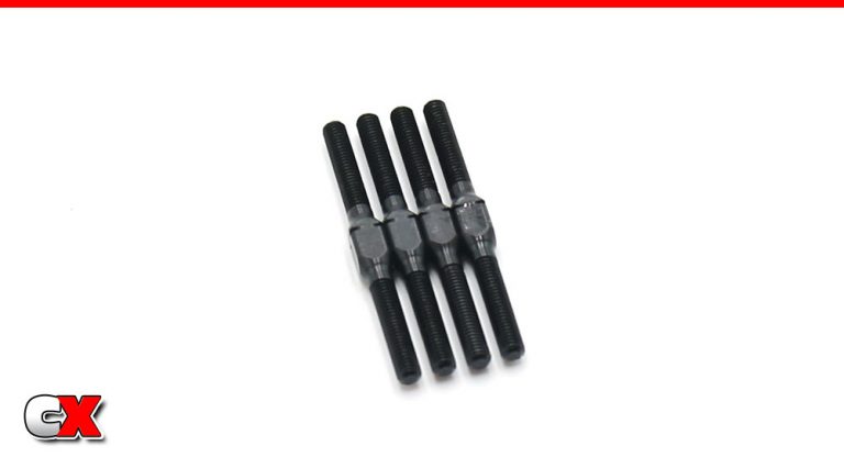
Thankfully, Tekno has made the front camber and steering turnbuckles the same size.
Step 15:
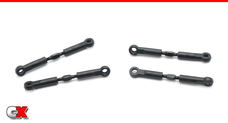
Build 2 steering and 2 camber link turnbuckles.
Step 16:
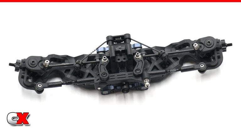
Attach the steering turnbuckles. Make sure the notch in the turnbuckles is pointing to the left side of the car.
Step 17:
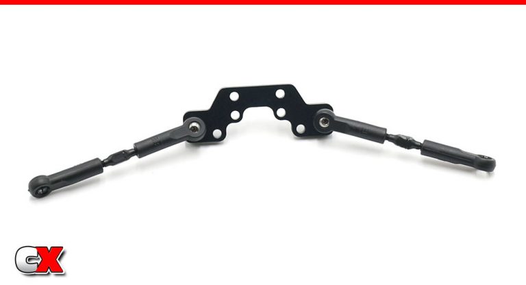
Assemble the camber link plate (link you did with the rear) and attach the camber links to it.
Step 18:
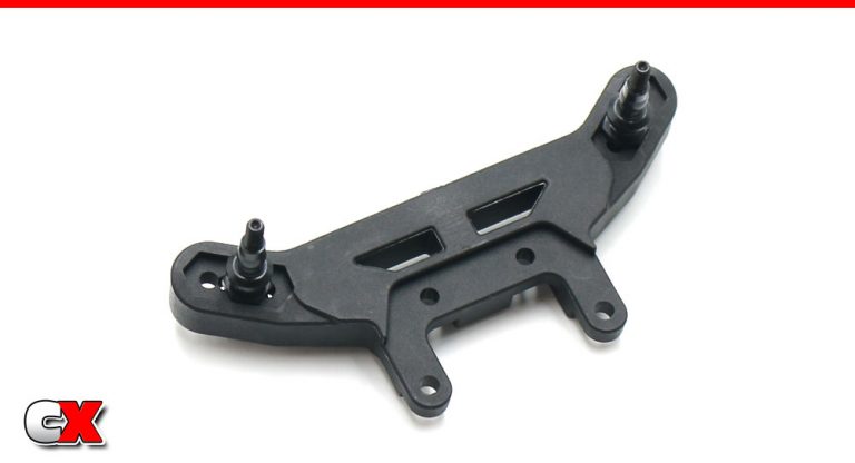
Assemble the front shock tower. Note the orientation of the shock standoffs.
Step 19:
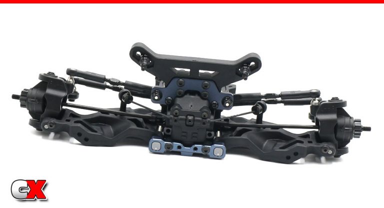
Press the shock tower into place on the bulkhead followed by the camber link plate. Six screws will hold it all together (2x M3x10mm, 4x M3x14mm). Once attached, key the CVD to the outdrive and pop the remaining turnbuckle links into place.
Again, make sure the Tekno “T” (on the ballcups) are always facing up.
And – BAM! Front clip of your Tekno EB410.2 is done. Nice job! Let’s start getting all of this mounted to the chassis.
Tekno RC EB410.2 4WD Buggy Build – Part 6
In this step, we’ll be attaching the front clip, the rear clip and the center diff to the chassis.
Build Notes:
None in this step.
Step 1:
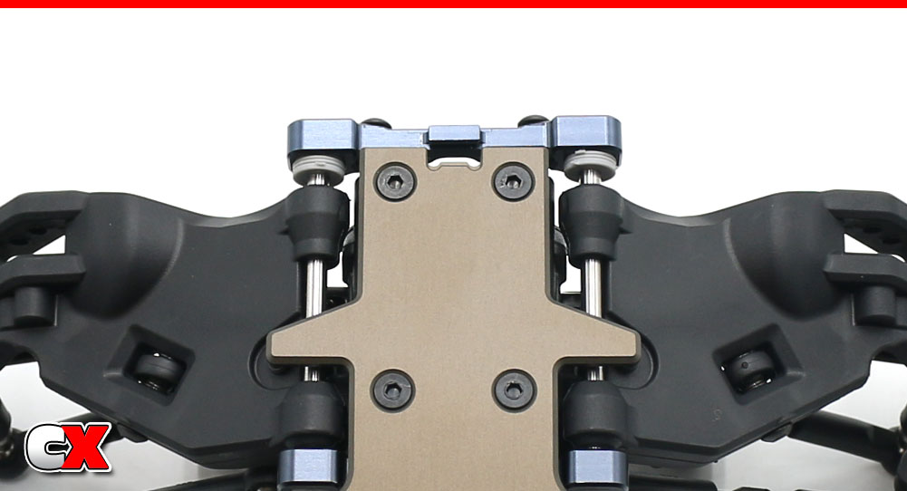
The manual shows the removal of the A arm mount to attach the front clip. Knowing that this would probably result in little shims flying everywhere and hingepins falling out, I opted to try a different method that actually worked out.
Back the screws out that hold the A arm mount in place – maybe 3/4 of the way. This will allow the A arm mount to slide out enough to allow attachment of the front clip, but not allow the hingepins and shims to fall out. Once you get the front clip attached to the chassis, slide the A arm mount back in place and tighten up the screws.
The A arm mount should ‘grab’ the little lip in the chassis.
Step 2:
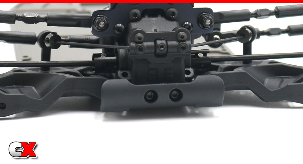
Attach the front bumper to the chassis.
Step 3:
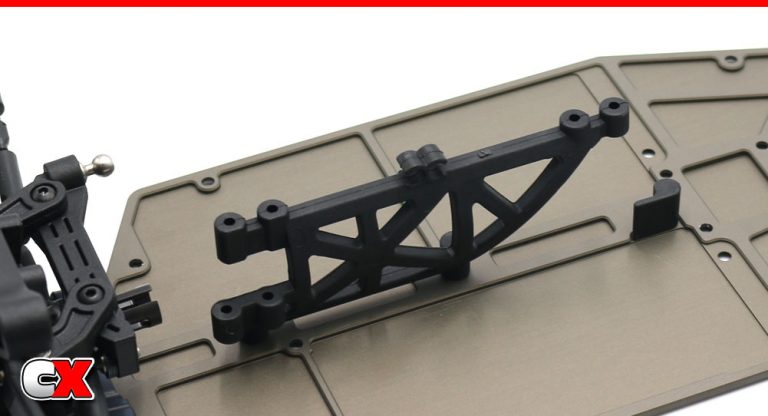
Install the center brace and battery stop to the chassis.
Step 4:
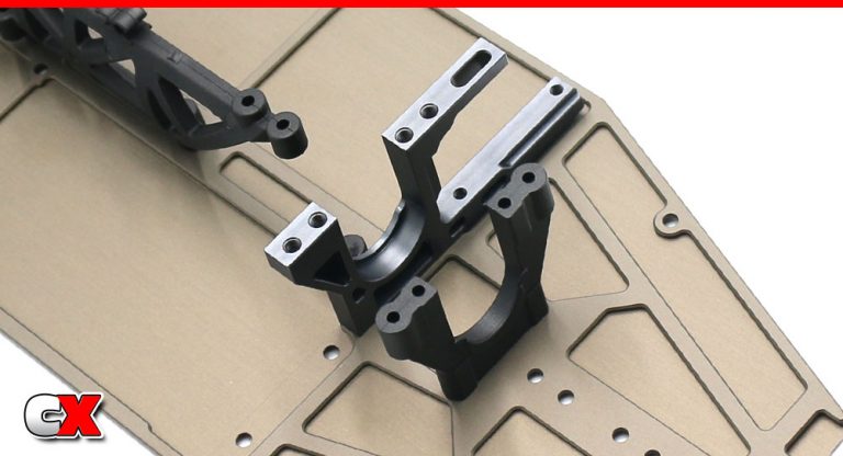
Attach the motor mount and rear diff bulkhead to the chassis. Note the orientation of both. A small drop of threadlock should be applied to the screws going into the aluminum mount.
Step 5:
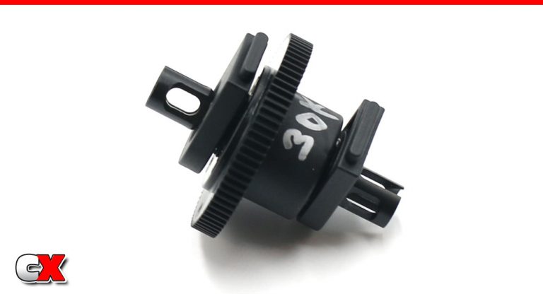
Slide a 10×15 bearing onto each side of the diff, then press the bearing supports into place. Give the bearings (and supports) a good push to make sure they seat as close to the diff as possible.
Step 6:
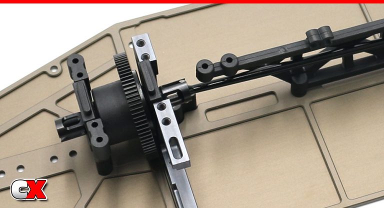
Key the front driveshaft to the front and center outdrives, then drop the center diff into place. Note how the bearing supports (on the center diff bearings) key to the center bulkheads.
(I noticed the picture isn’t great, but they bearing supports do key to the bulkheads if installed correctly).
Step 7:
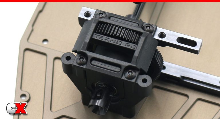
Cap the center diff. The cap is not directional so it can go either way.
Step 8:
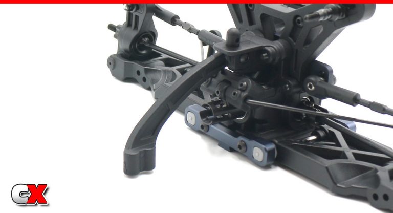
Attach the rear support brace to the rear clip. You can use one brace, two braces or no braces depending on the traction level you are looking for (no braces, more traction, both braces less traction).
Step 9:
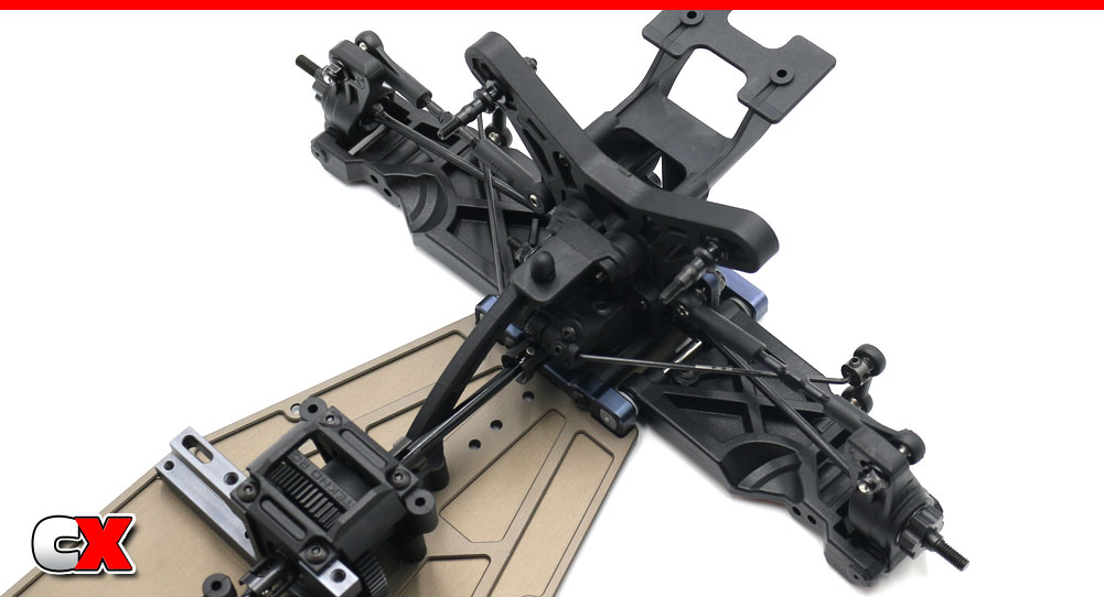
Key the rear driveshaft to the rear and center outdrives, then attach the rear clip to the chassis.
Easy peasy, right? Your Tekno EB410.2 is starting to take shape! Good job – let’s move on to Step 7 – the shocks.
Tekno RC EB410.2 4WD Buggy Build – Part 7
Tekno’s EB410.2 uses a top-of-the-line set of big bore shocks. They include aluminum threaded bodies, bottom-load cartridges, massive plastic caps (with integrated bleeder hole) and a grub-screw lower portion that keeps the lower spring retainer from popping off. Good stuff!
Build Notes:
Tekno provides #600 weight fluid with the kit (equivalent to 60wt), but I would check with your local track to see what guys there are running. Building shocks with the right fluid the first time is way more fun than having to rebuild them later.
Fluids will be used in this step, and that can get messy at times. Some rags or paper towels should be handy for cleaning up any spills.
Step 1:
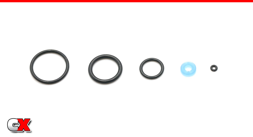
The kit shocks come with 5 different o-rings in the kit (from left to right): shock collar o-ring, inner shock cap o-ring, lower cartridge o-ring, internal cartridge X-ring and bleeder screw o-ring.
Step 2:
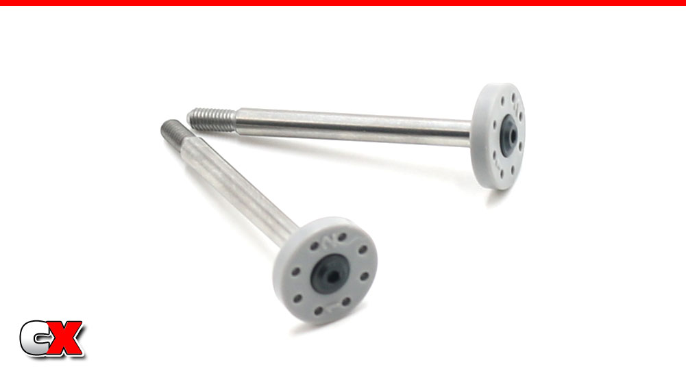
We’re going to work on the front shocks first – build your pair of front shock shafts. A light drop of threadlocker on the screw is suggested.
Step 3:
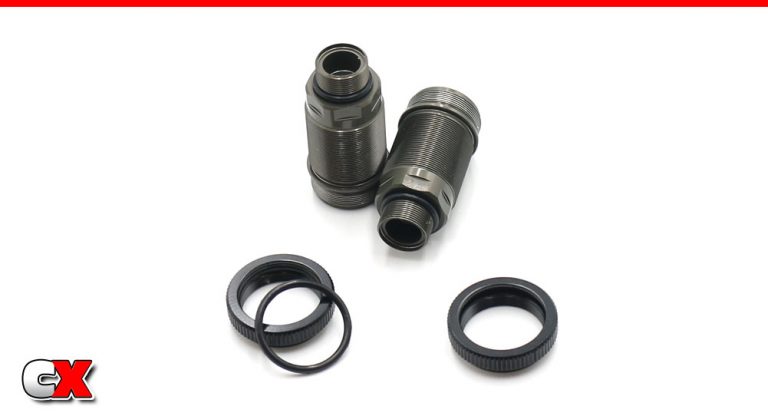
Install some o-rings; one pair into the shock collars, one pair over the bottom of the shock cartridge area.
Step 4:
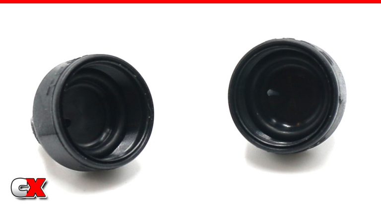
Install one more pair of o-rings into the shock caps. Take an extra moment here to make sure these seat all the way in the cap.
Step 5:
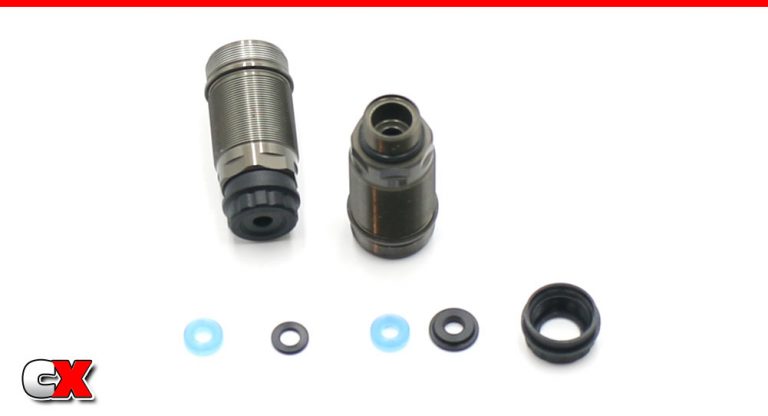
Assemble the bottom shock cartridge; blue X-ring, plastic guide, another X-ring and the final guide (note the lip on this last part – it should be facing away from the shock body). Screw on the shock cartridge cap.
Step 6:
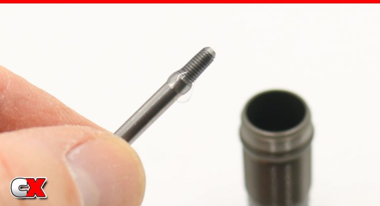
Apply a small amount of shock fluid to the threads of the shock shaft assembly…
Step 7:
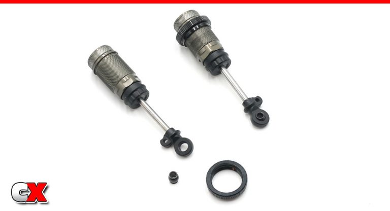
…and slowly slide it through the body. The fluid helps prevent the threads from tearing the X-rings.
Press the aluminum ball into the shock bottoms, then install the bottoms on the shafts. Tekno has the gap between the bottom cartridge and the shock bottoms at 23mm – I screwed the shock bottoms on until I reached that gap.
Install the shock collars; a slight drop of shock fluid on the body – at the start of the threads – will help lubricate the thread and make installing the collars much easier.
Step 8:
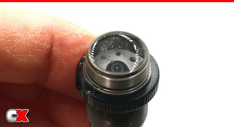
Fill the shocks with fluid, then SLOWLY pump the shaft up and down until all the bubbles have been released from under the piston. Set the shock aside so the bubbles can rise and dissipate. Build 2 shocks.
Step 9:
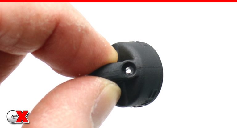
While we’re waiting for the bubbles to float away, let’s check out the shock caps. Here you can see that Tekno has already pre-drilled the caps – love this!
Step 10:
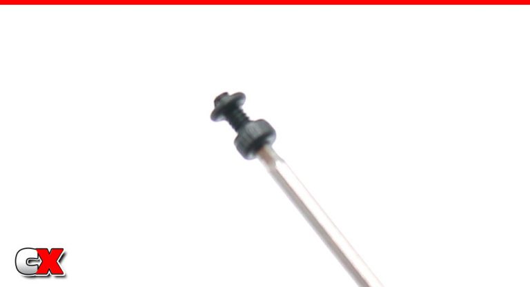
Slide the bleeder screw o-rings on to the screws.
Step 11:
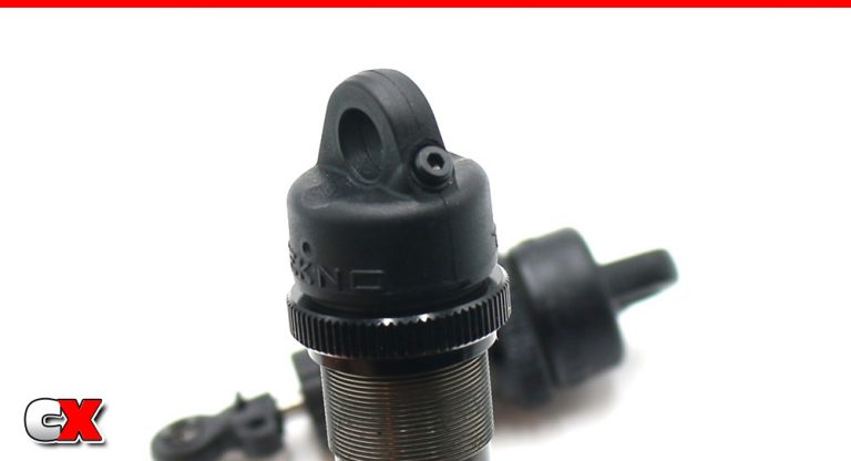
With the piston pulled all the way out of your shocks, add a little more fluid until it is crowning the top of the shock, then attach the cap. Compress the shock all the way, then install the bleeder screw.
Most likely a little fluid will come out of the bleeder hole in the cap, so be prepared with some towels for clean up.
Step 12:
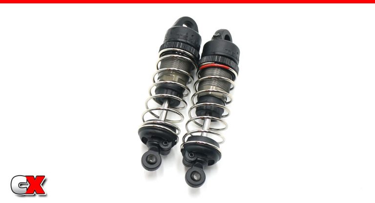
Install the front spring and the lower spring retainer. Use the M3x8mm grub screw to retain the spring retainer.
Step 13:
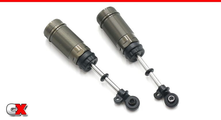
The rear shocks are similar to the fronts, only longer. Build like the fronts up until this point, using the manual-set 29mm as the shock shaft gap length. The only difference is the addition of the black o-ring on the shaft.
Step 14:
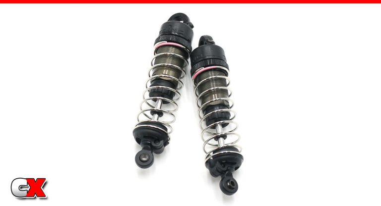
Add oil, release the bubbles, add the cap and bleed. Add the spring and lower retainer; add the grub screw.
Step 15:
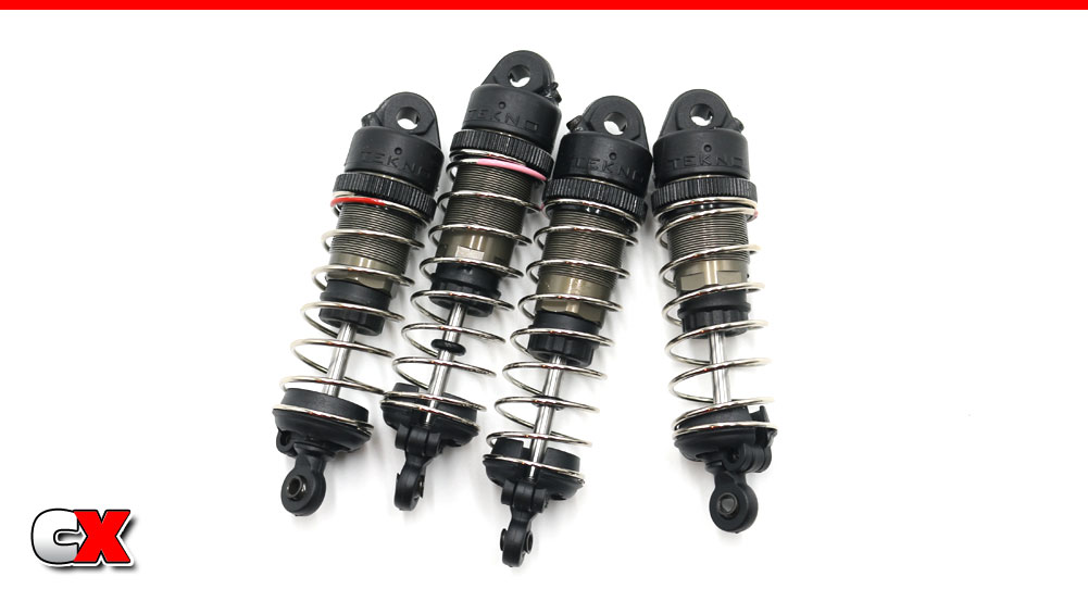
Add the shock cap bushings to all 4 shocks. Your pretty little dampers should look like this, ready for install.
Clean off any extra fluid that may have come out during the bleeding process.
Step 16:
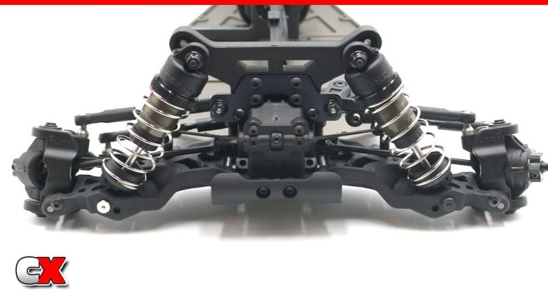
Install the front shocks – mount on the tower, outside hole in the arm. Make sure you use the reverse-thread chrome screw on the right side of the car, the normal-thread black screw on the left side.
Step 17:
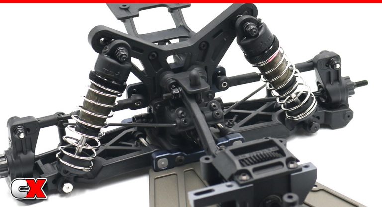
Install the rear shocks – mount on the tower, inside hole in the arm. Make sure you use the reverse-thread chrome screw on the right side of the car, the normal-thread black screw on the left side.
Shocks in place, ready to soak up the track! Awesome job! Let’s gather your electronics and move on to Part 8!
Tekno RC EB410.2 4WD Buggy Build – Part 8
The Tekno EB410.2 can accept most major electronics; tall or short servos and normal sized receivers. Most brushless ESC’s fit as well, however you might need to get creative if they come with external capacitors.
Build Notes:
Chassis space is a little limited for electronics, so I would do a little research before buying.
Step 1:
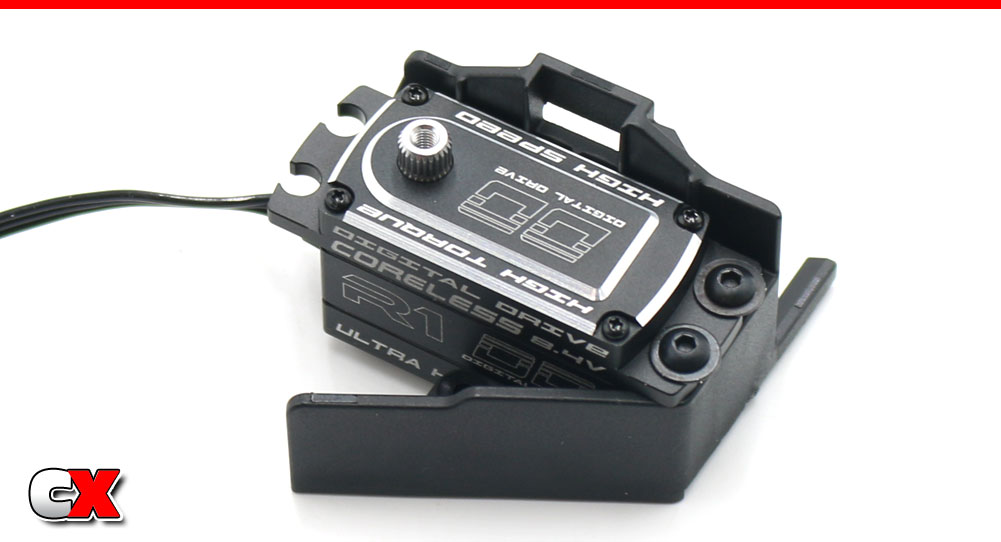
As mentioned at the beginning of this build, we’re using a R1 Wurks Low-Profile Digital Drive Servo. This particular one also comes with a short servo lead so we won’t have a ton of extra wire getting tangled up.
Step 1 – attach your servo to the mount as shown.
Step 2:
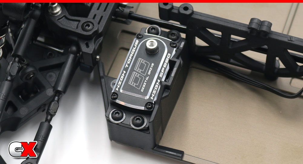
Attach the servo assembly to the chassis. It’s best to route your wire to the opposite side of the buggy now (as you can see I didn’t and had to remount it again at a later time).
This mount also doubles as the forward battery retainer.
Step 3:
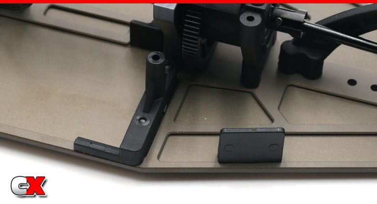
Attach the rear battery retainer to the chassis along with the rear body mount panel.
Step 4:
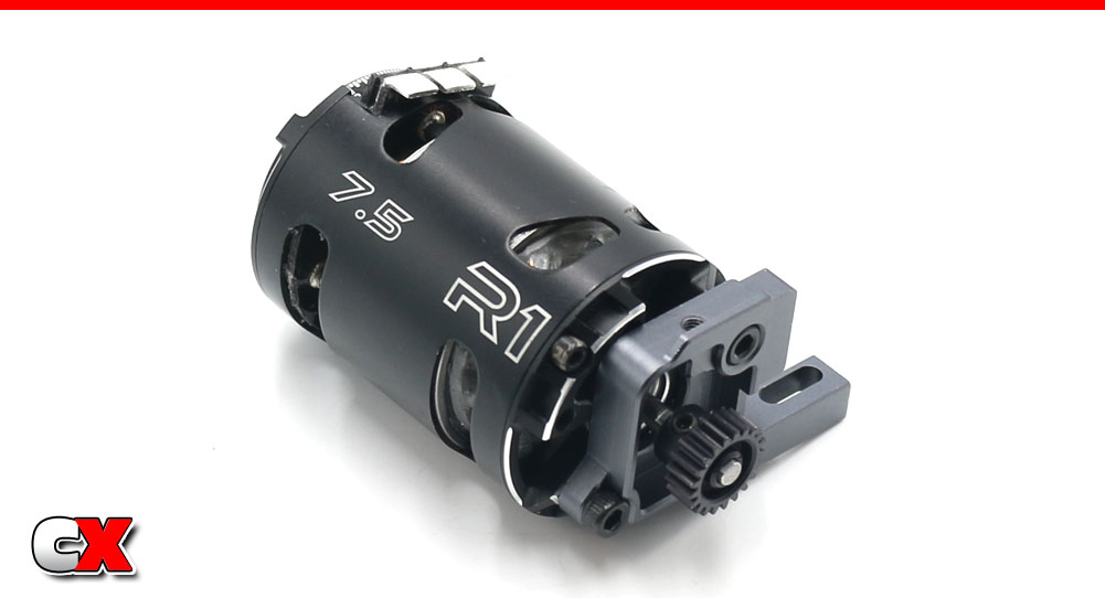
Attach your motor to the motor mount. I would suggest aligning it up similar to the picture, with the motor tabs facing up.
If you know what pinion you’ll be using, you can add that now as well.
Step 5:
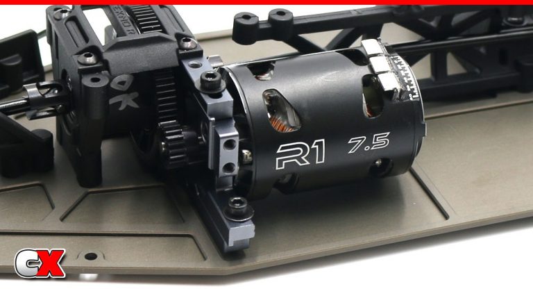
Slide your motor assembly in place. Set your gear mesh and tighten down the M3x10mm screws.
Step 6:
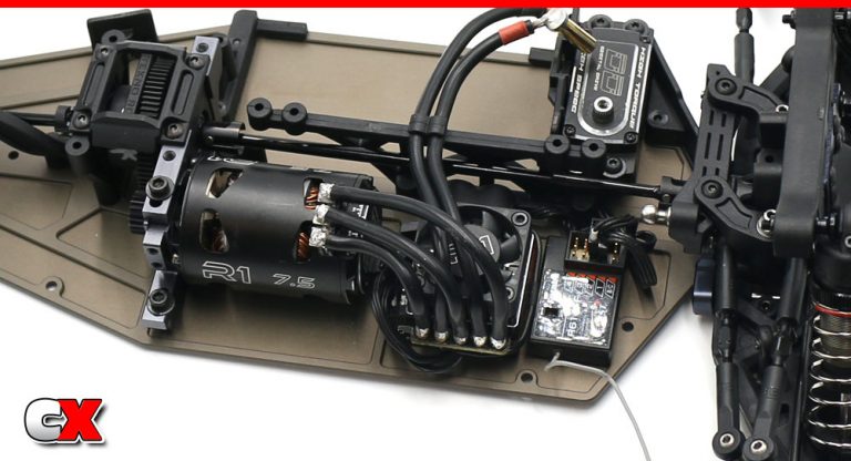
Install your ESC and receiver. You’ll want to make sure both the ESC and receiver are far enough on the chassis that they won’t interfere with the right-side side guard.
It’s also the best time to tidy up your wiring. Once you get the other side guard on, things get pretty tight.
Step 7:
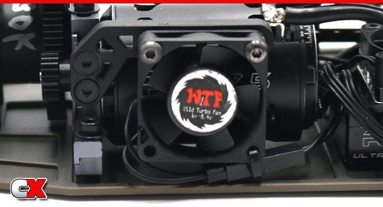
Optional step; if you have a motor fan, you can attach it using the Tekno-supplied motor fan mount.
I had a spare WTF fan (that means Wild Turbo Fan) off of my EB410 that I used on here.
Step 8:
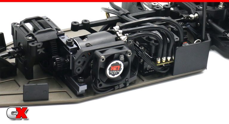
Attach the front side guard and rear body panel.
Another look at the mounted WTF fan.
Step 9:
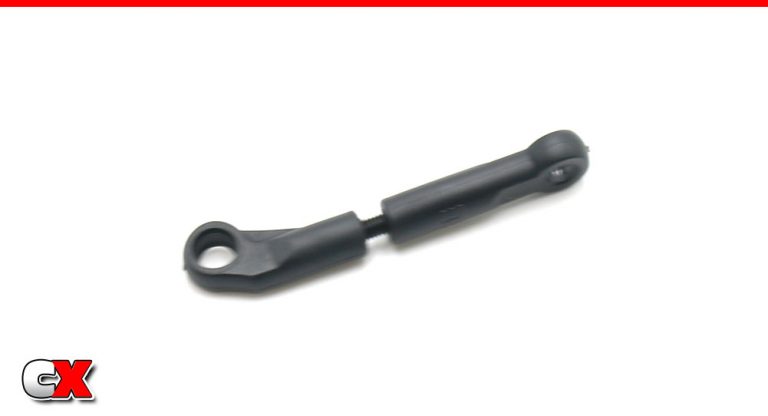
Build the steering drag link (with a 3mm gap in between).
Step 10:
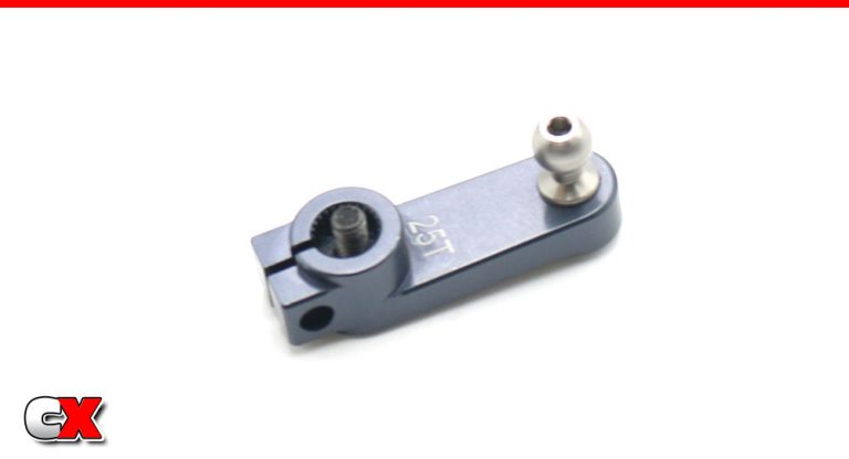
Assemble the servo horn. This is the only upgrade I made to the EB410 and decided to bring it over to the .2. It’s a Tekno unit (TKR6563A Aluminum 25T Servo Horn) and is a must-have upgrade over the plastic horn.
Buy here: https://amzn.to/3bU5Ygf
Step 11:
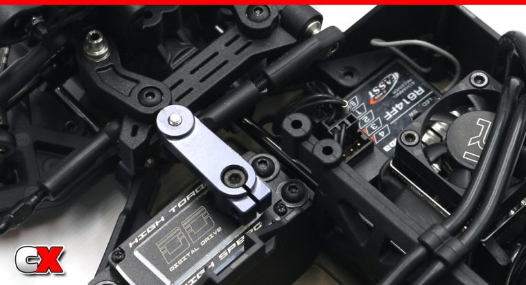
Final step is to attach the servo horn, then connect the drag link to the steering rack!
Woo hoo! Tekno EB410.2 is almost complete! Final few steps and we’re ready to get this baby on in the dirt!
Tekno RC EB410.2 4WD Buggy Build – Part 9
In this final step of the Tekno EB410.2 build, we’ll be installing the body mounts, wing, wheels and tires and body. Quick and easy so we can get it on the track for some fun!
Build Notes:
The rear wing can be mounted forward or rearward with a 0, 5 or 10mm lift.
Tekno gives you two body installation options; body clips or Velcro. I chose body clips; if you want to use the Velco mounting system, refer to the manual for adding the provided Velcro squares.
Step 1:
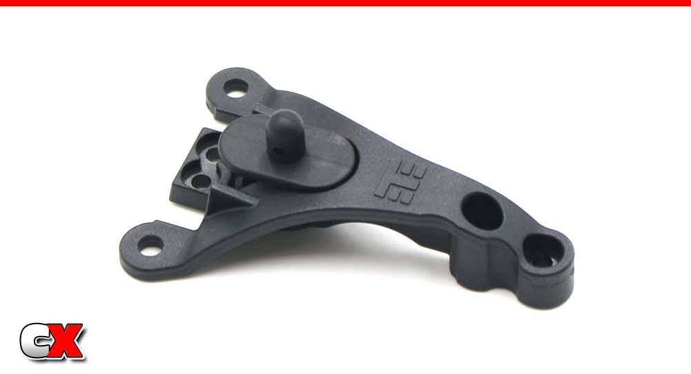
Assemble the front body mount/chassis brace.
Step 2:
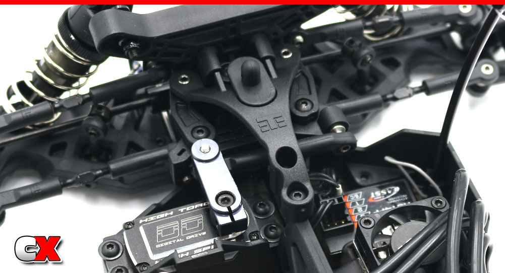
Install.
Step 3:
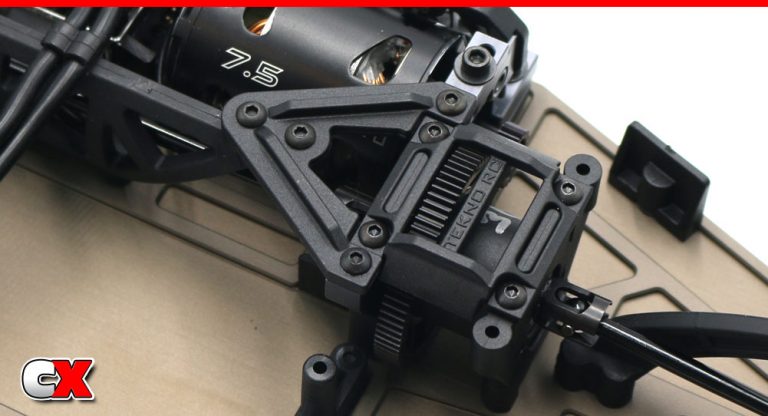
Attach the center differential chassis brace. A light dab of threadlocker is suggested for the 2 screws going into the aluminum bulkhead.
Step 4:
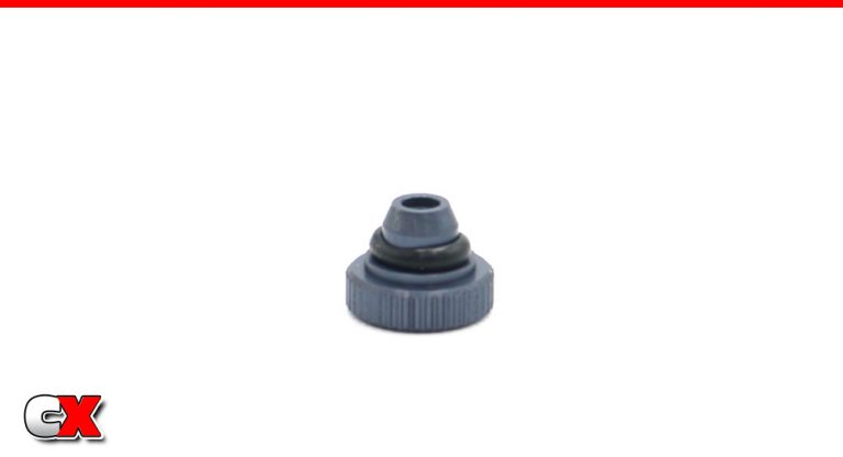
Slip the o-ring over the thumbwheel.
Step 5:
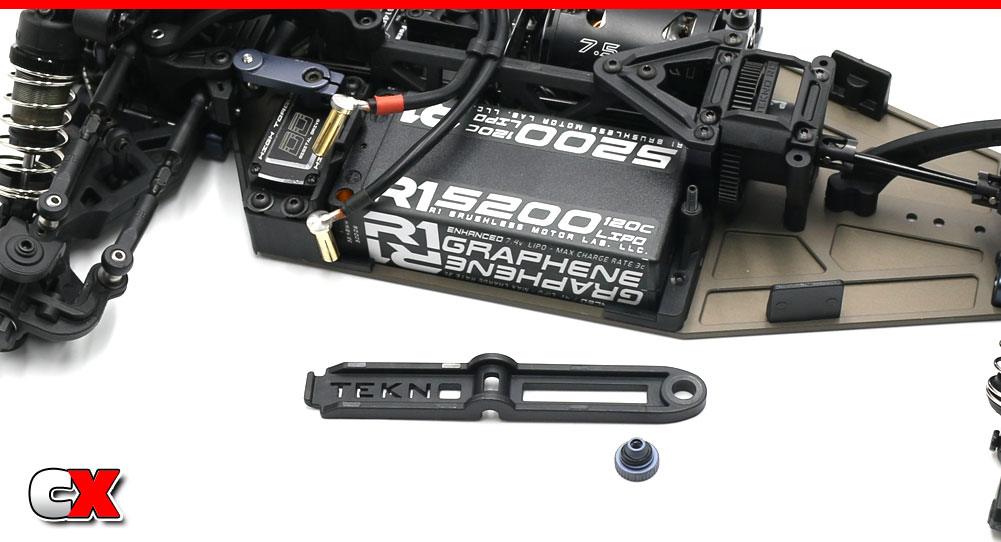
Install the M3x18 grub screw into the rear battery retainer with approximately 8mm sticking out.
Drop your battery into the tray, attach the battery strap and secure with the thumbwheel.
Step 6:
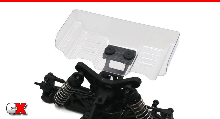
Attach the rear wing. I’m starting with the box stock mounting; all the way forward with a 5mm lift.
Step 7:
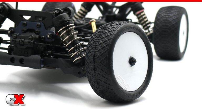
Attach your wheel/tire combo to the buggy. Use the tiny (but certainly effective) wheelnuts to keep the tire assemblies in place.
Step 8:
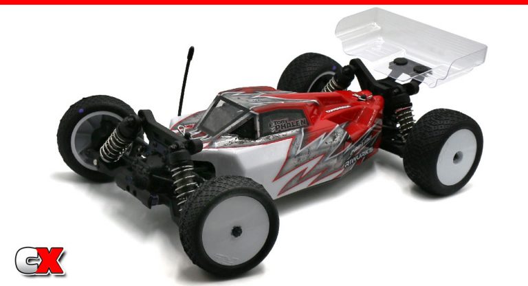
Finally, install the body.
That’s it – you’re done with your Tekno EB410.2 Competition Buggy! Time to charge up a pack and take ‘er to the track!
Thanks for following along with this build. It’s been a fun one for sure and I can’t wait to get some video of this buggy!! Stay tuned…

