

Tamiya CC-02 Trail Truck Online Build
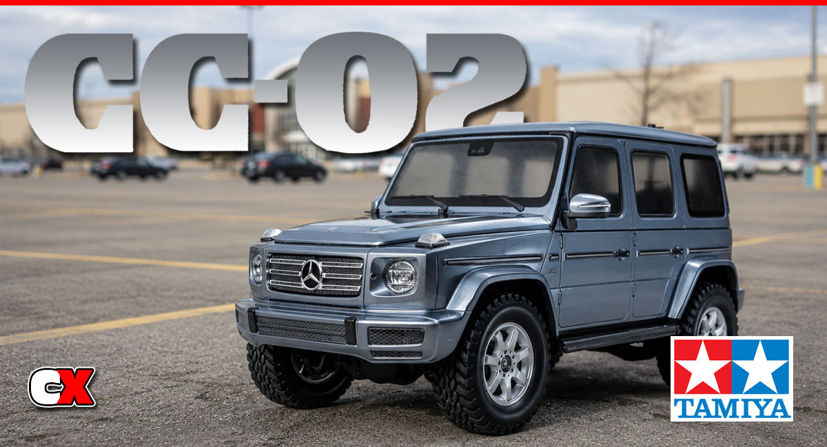
Tamiya’s CC-01 chassis has been on the longest running trail truck chassis’ to date. It featured a faux ladder-frame design that surrounded a single-piece tub chassis and included a front independent/ rear solid axle suspension. The servo was mounted offset near the front of the chassis, the transmission in the center and the ESC and receiver sat atop the battery tray (molded for shotgun-style only battery packs).
This was a super cool design back in the day and hardcore Tamiya people really loved it but, as years progressed, the trail truck segment became way more advanced, leaving the CC-01 behind.
Finally, Tamiya thought it was time to update the aged CC-01, adding current features like a 4-link front/rear suspension, adjustable transmission, solid axles and a battery tray that would accept both shotgun and standard, box-shaped LiPo batteries!
This article will take you through the entire build process minus the body (it’s a Tamiya body – those take quite a bit of time).
Tamiya CC-02 Trail Truck Online Build – Part 1
Tamiya’s new CC-02 transmission features robust gears inside a nice looking housing. One of the cool things about it is that you can build it one of two ways; standard, with gear ratios between 11.09:1 to 17:33.1 or low-speed, with ratios between 18.74:1 to 29.28:1 (both require optional pinions). Best part is – it’s a simple swap of the way the gears install! No additional parts are necessary.
Build Notes:
I suggest deciding on how you want to build your transmission up front; having to pull it apart to re-configure it will require a LOT of screws.
The CC-02 comes with a 0.6 Mod spur gear, however the adapter will allow you to swap to 48P (or even 32P). This should open up a wider range of gears to use.
To help identify the gears, all of them come from the factory with the tooth count printed on them.
Step 1:
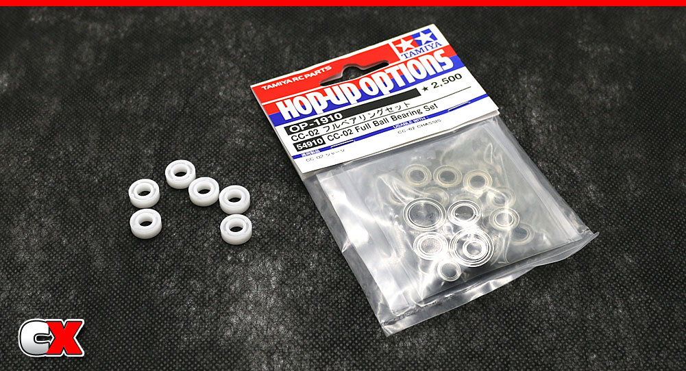
Before building, you might want to get your hands on a complete set of CC-02 ball bearings. These will not only help the performance of your rig, the will also be much easier to install during the build. I’m using the bearing kit sold by Tamiya, Part #54910.
Step 2:
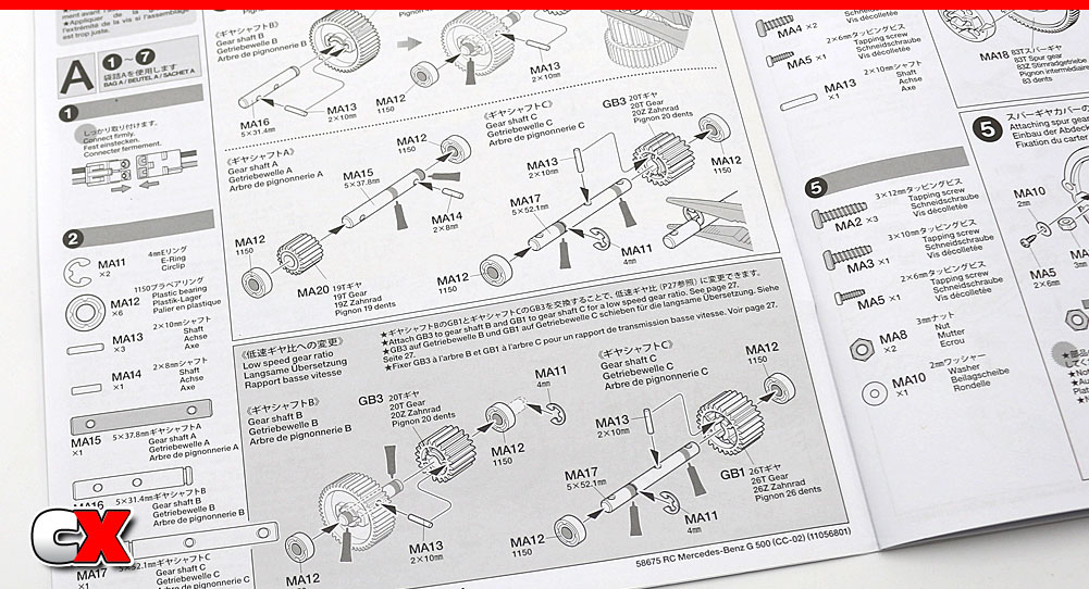
As stated in the notes above, you can build the transmission with either standard or low-speed gearing. It’s a simple matter of the build – no additional parts are needed. I’ll be building the transmission with the low-speed setting (I want this thing to crawl, baby!).
Step 3:
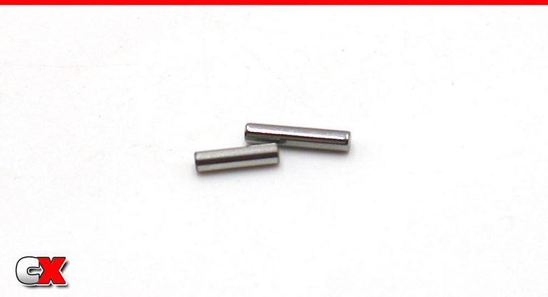
The transmission pins come in two lengths; an 8mm and a 10mm. Make sure you pay close attention as to which one goes where during the build.
Step 4:
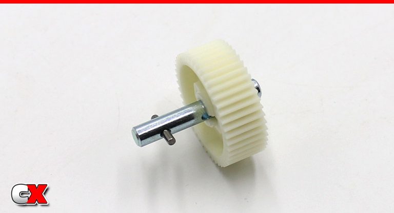
All righty – first thing to do is assemble the Gear Shaft B. Slip a 10mm pin in the B shaft and slide the gear in place, keying the gear to the pin.
Step 5:
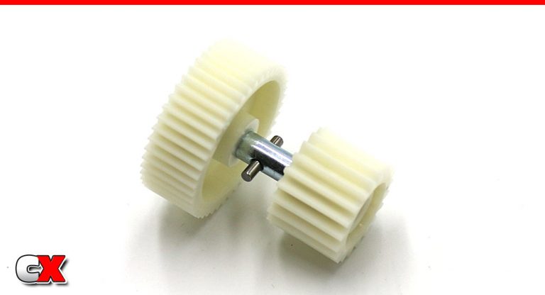
Slip another 10mm pin into the other hole, then key the gear to it.
Since we are building with the low-speed gear set, this will be the 20T gear. If you are building the standard transmission, this will be the 26T gear.
Step 6:
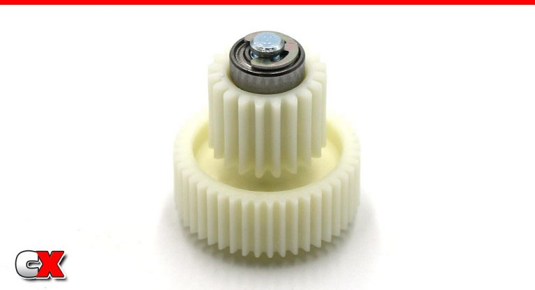
Slide a bearing on both ends of the assembly and use an e-clip to capture as shown (only one side gets captured).
Step 7:
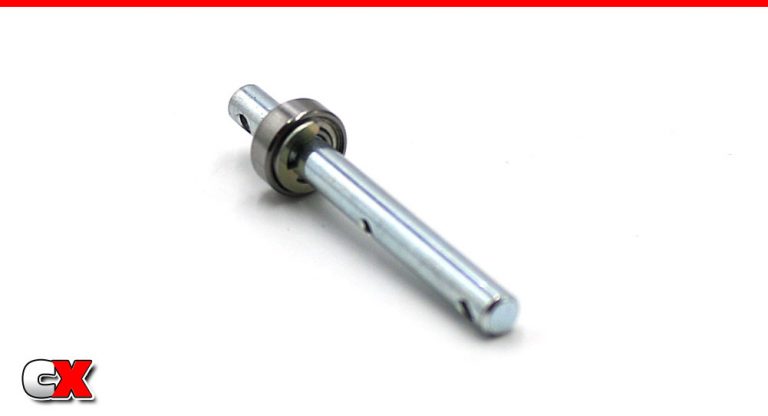
Attach an e-clip to Gear Shaft C and slide a bearing into place.
Step 8:
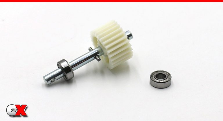
Insert a 10mm pin into the hole, then slide the 26T gear into place and key to the pin. Add another bearing to the gear-end of the shaft.
This is for the low-speed setup; if you are building the standard transmission, this gear will be the 20T one.
Step 9:
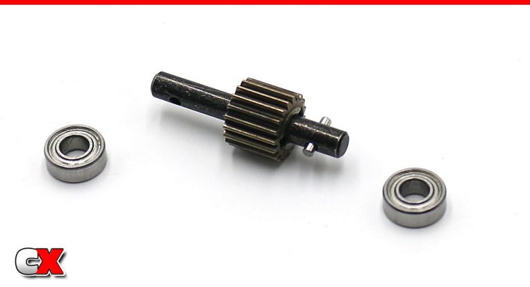
Slide an 8mm pin into Gear Shaft A, then slide the 19T gear into place. Add a bearing to each end.
This gear tends to slip around some, causing the 8mm pin to fall out. A light dab of grease on this pin will help keep it (and the gear) in place.
Step 10:
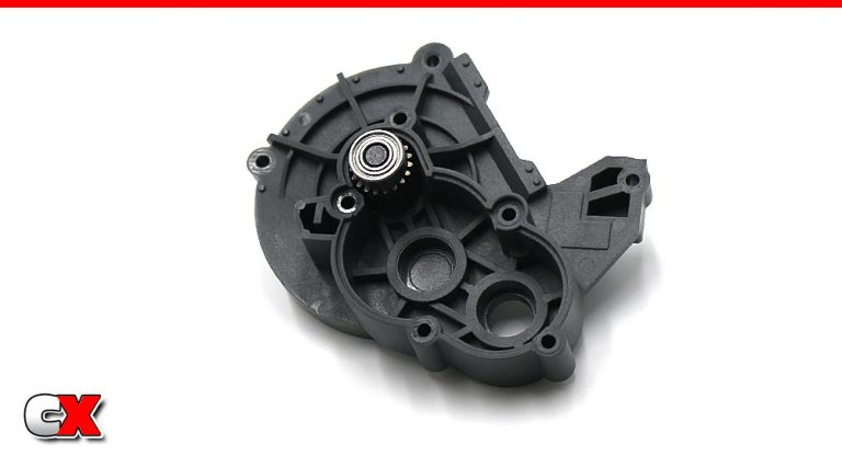
Slide Gear Shaft A assembly into the gearbox as shown. Make sure that pin doesn’t come sliding out.
Step 11:
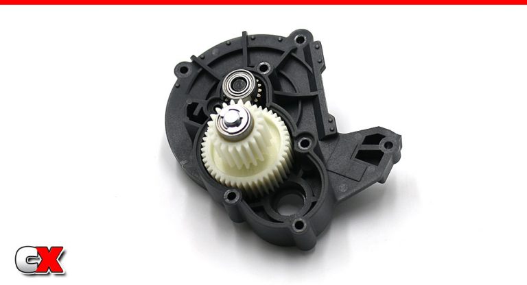
Slide Gear Shaft B assembly into place.
Step 12:
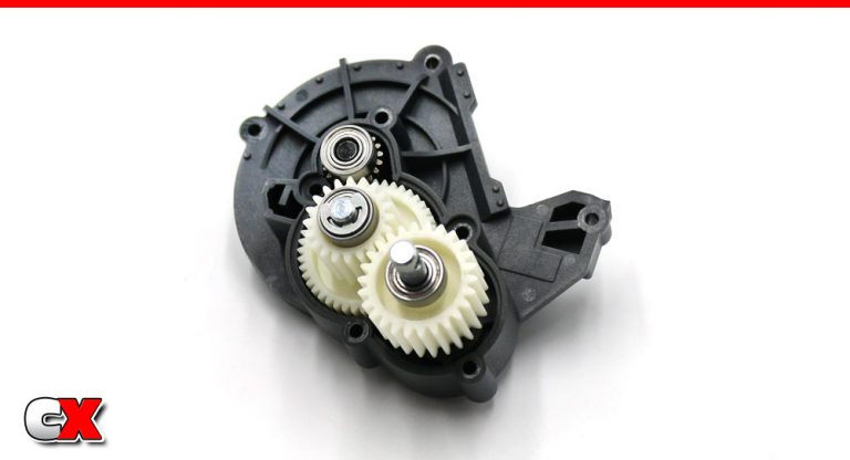
Finally, slide Gear Shaft C into place. Set aside for a moment.
Step 13:
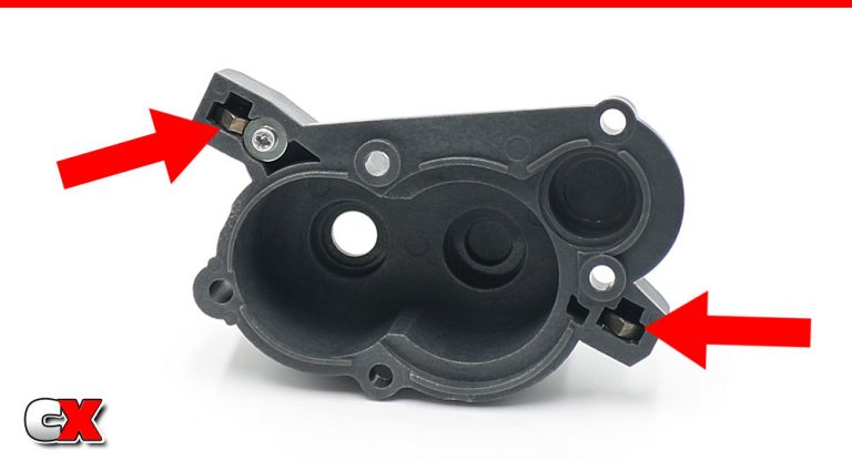
The opposite side of the transmission case needs to have two 3mm nuts installed (see red arrows). The one on the left is captured by the 2x6mm screw and 2mm washer. The one on the right can be held in place with a light dab of grease.
Step 14:
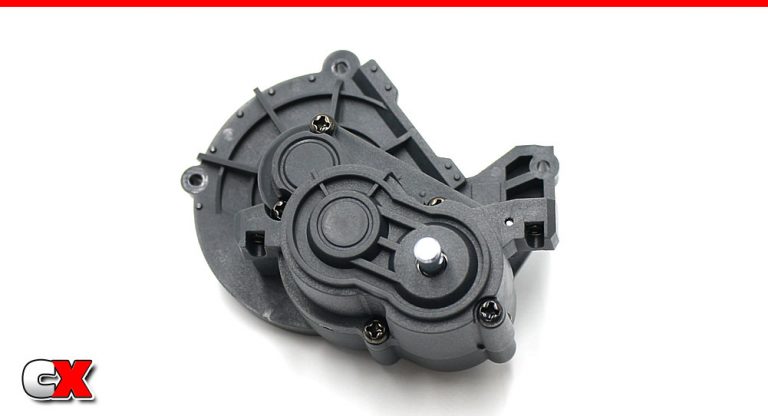
Add a light layer of grease to the gears and spin them slowly to coat them. Mate the two transmission halves together and secure with the five screws.
Step 15:
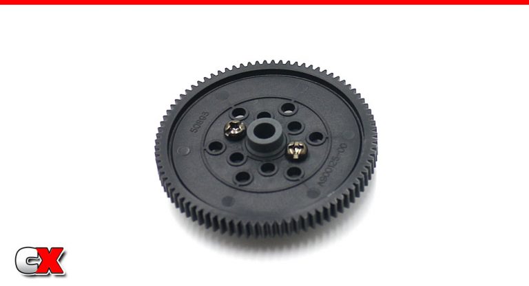
Attach the 83T spur gear to the spur gear mount. Do not overtighten the screws.
Step 16:
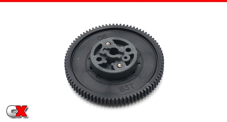
Even though the mount is on this side, this will be the FRONT side of the gear (the part exposed once mounted). While not necessary, it’s a good idea to mount the spur gear with the tooth count facing out to easily identify it.
Step 17:
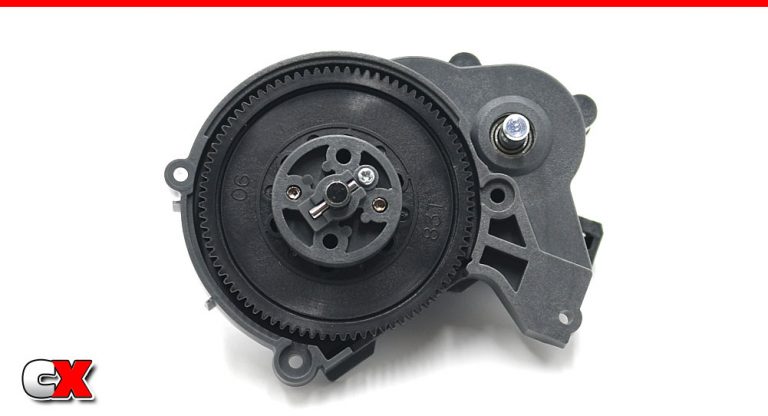
Slide the spur gear assembly onto the top shaft, then slip a 10mm pin through the hole. Tamiya captures the pin with a 2x6mm screw – smart!
Step 18:
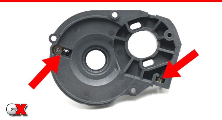
Take the gear cover and insert two more 3mm nuts into it (see red arrows). Again, the left one is captured with a 2x6mm screw and 2mm nut. The right will need a dab of grease to keep it in place.
Step 19:
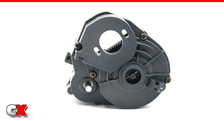
Attach the gear cover assembly to the transmission; four screws keep it in place (note the different lengths in the manual).
Step 20:
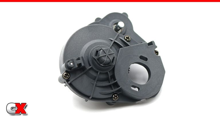
Pop the little cover into place. While not available at this time, I’m guessing Tamiya will be releasing a slipper clutch for the CC-02. This cover can then be removed to externally adjust it.
Step 21:
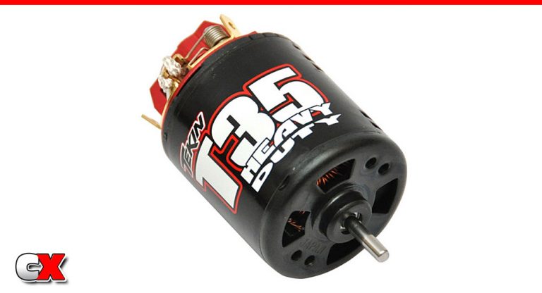
As we mentioned earlier, we’ll be using a Tekin T35 Heavy Duty brushed motor in the CC-02. Some serious grunt from this thing, especially on 3S!
Step 22:
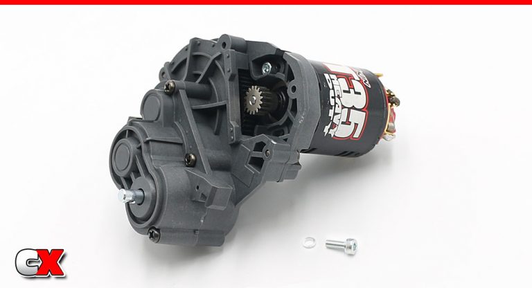
Slide the pinion gear onto the output shaft and attach the motor assembly to the transmission. One of the great things about this transmission is that the mounting is not typical Tamiya. Usually, there are pre-determined holes for the gearing – Tamiya now includes slots for motor adjustment.
Use the two 3x8mm (and .7mm washers) to secure the motor.
Step 23:
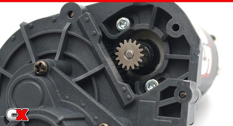
A closer look at the gear mesh – not too tight, not too loose.
Step 24:
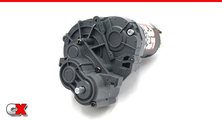
Finally, attach the cover – one more 3x8mm screw to hold it in place!
Excellent job on the transmission. It would be interesting to know who built it in standard or low-gear format!!!
Ok, set the transmission aside and let’s move on to Part 2 – the Chassis assembly.
Tamiya CC-02 Trail Truck Online Build – Part 2
The chassis on the CC-02 has been revised big time – it now features a true c-channel design. About 80% of it’s length is molded in plastic with separate metal ‘extensions’ at both ends (each about 2 1/2″ long). These provide rigid end points to the chassis, however I think these are Tamiya’s ingenious way of making the chassis longer down the road. Simply make longer metal pieces and wah-lah … a longer chassis.
Build Notes:
The chassis seems overly-engineered, with tons of M3 nuts capturing all the screws that connect the frame rails together. You’ll need to use a little grease to keep the nuts in their sockets (see Steps below for more info).
The servo can be mounted one of two ways; with the output shaft facing down or towards the front of the car. I opted for down but, at this time, can’t give you a explanation if one way is better than the other.
The shock towers are marked with an A and B and are directional – pay close attention when mounting them.
Step 4 has you assembling and ‘pasting’ the plastic locknut holder to the frame rail – this is never going to stay. Put this assembly aside; we’ll be installing it in Step 21.
Step 1:
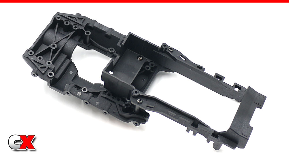
Attach the battery tray to the lower chassis deck.
Step 2:
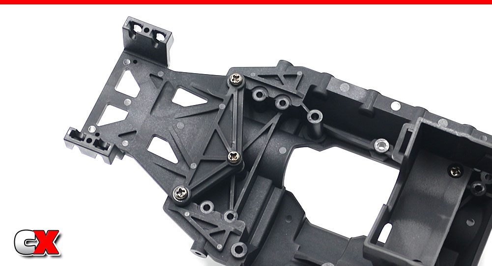
Attach the servo mount to the lower chassis deck.
Step 3:
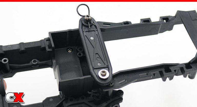
Assemble the battery holddown strap. It was much easier if you install the mount screw first (to hold the strap in place), then the 3x18mm screw.
Step 4:
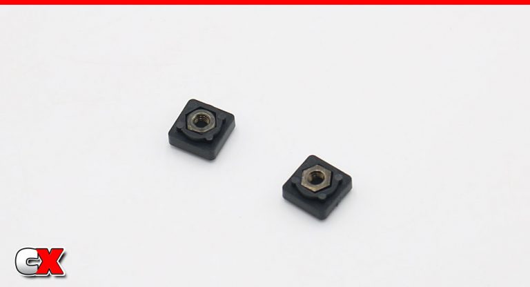
Assemble a pair of 3mm locknut holders. Again, the manual states to ‘paste’ them in place with some grease. Ya, no. Set them aside for a later step.
Step 5:
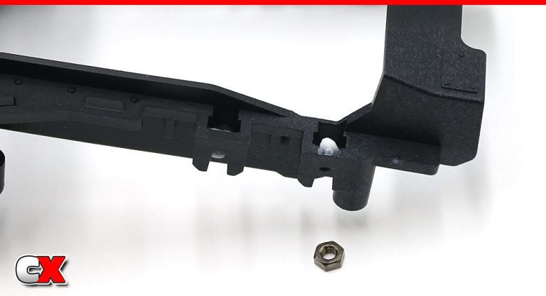
The chassis has pockets all down the sides – both sides. These pockets will be holding the 3mm nuts. Add a dab of grease to each pocket, then press a nut in.
Step 6:
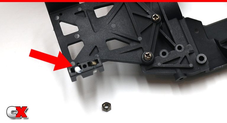
Up front – more grease, more nuts.
Step 7:
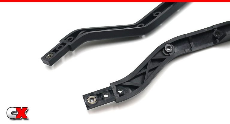
Add two 3mm nuts to the front of the frame rails as well. These are a press fit and won’t need any grease to keep them in place.
Step 8:
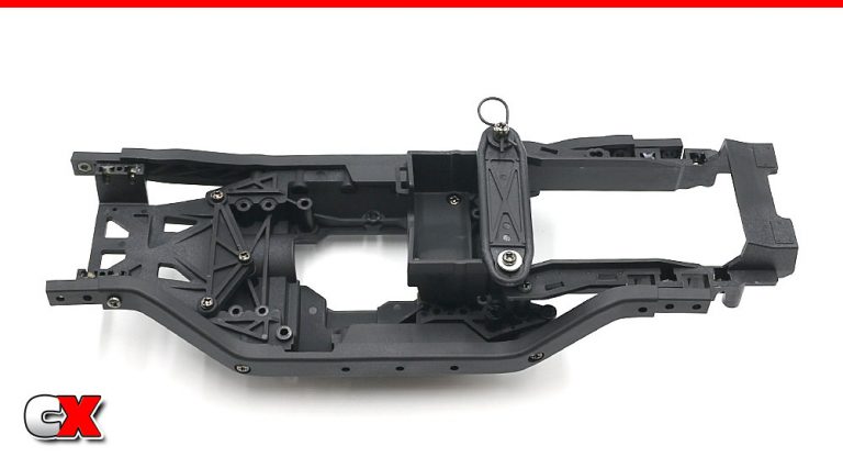
Now attach both frame rails to the chassis. Pay attention to the screws here.
Step 9:
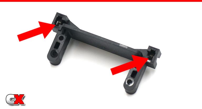
Grab the servo mount and install two 3mm nuts into the cavities as shown. A dab of grease will help keep them in place.
Step 10:
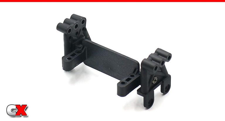
Attach the front shock towers. Note that they are directional (see the A and B printed on them).
There are two servo mounting options; I’ll be building the CC-02 with the servo output shaft facing down.
Step 11:
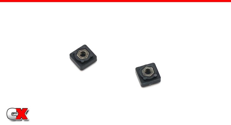
Build two more 3mm nut holders.
Step 12:
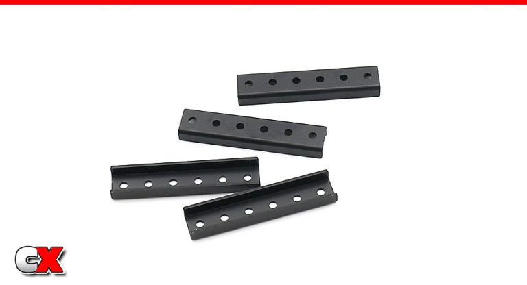
A closer look at the four aluminum frame rail extensions. All four are the same, so no need to worry about placement.
Step 13:
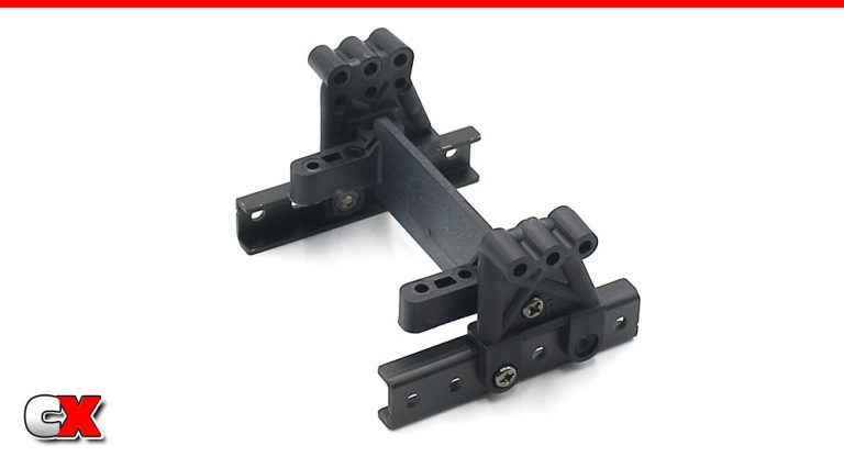
Attach a pair of aluminum frame rails to the servo mount. Front clip is done.
Step 14:
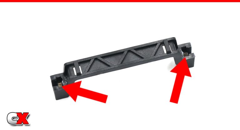
Moving to the rear. Slide a pair of 3mm nuts into the rear cross brace (grease is suggested here).
Step 15:
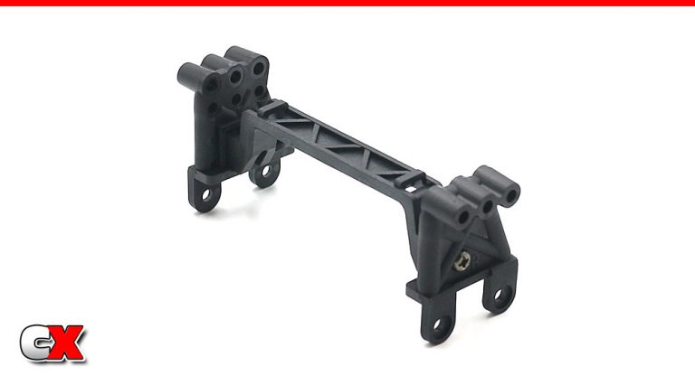
Attach the towers to the brace. Again, they are directional and marked with an A and B.
Step 16:
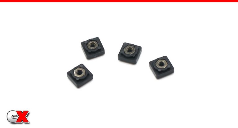
Build four 3mm nut holders.
Step 17:
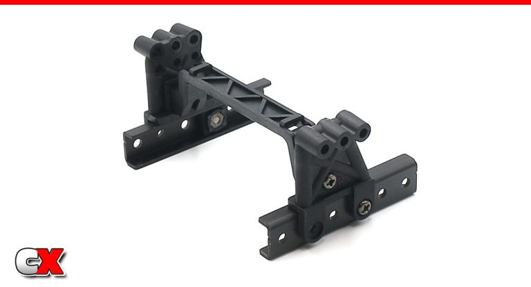
Attach the final two aluminum frame rails to the tower assembly. You’ll only be using two of the 3mm nut holders from Step 16 here.
Step 18:
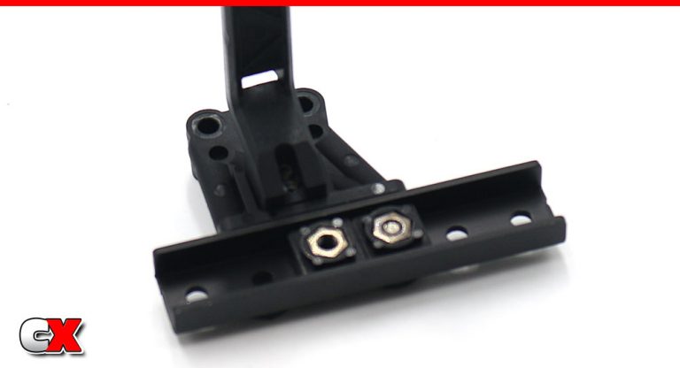
Now, slide the other two 3mm nut holders into place as shown. A light dab of grease will help keep them in place.
Step 19:
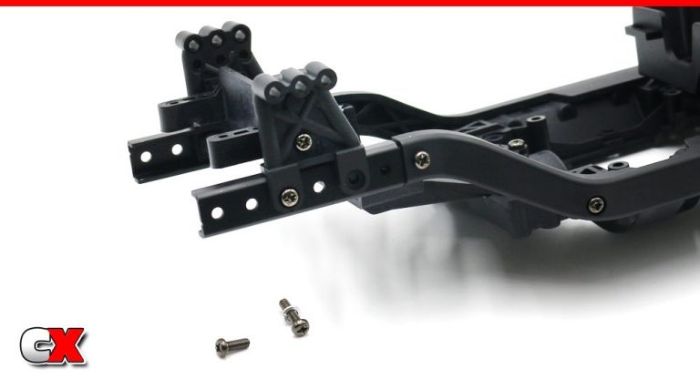
Slide the rear frame rail clip onto the rear of the chassis and secure with the screws.
Step 20:
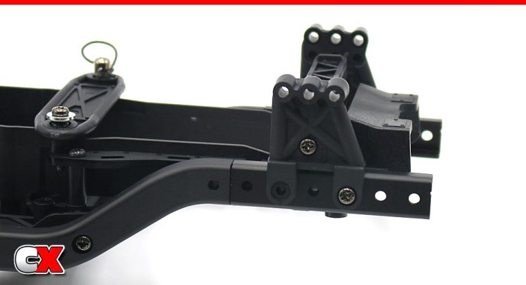
Slide the front frame rail clip onto the front of the chassis and secure with the screws.
Step 21:
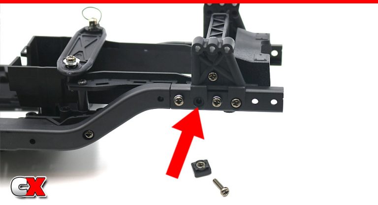
Here is where we can slip the 3mm nut holders from Step 4 into the pocket and secure with the 3x12mm screws. Trust me, this is WAY easier than trying to manage the earlier parts of the build with these ‘pasted’ in place.
Step 22:
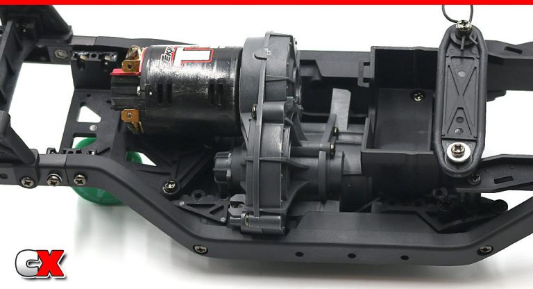
Wiggle the transmission into the belly of the chassis. It’s a process, for sure, but not all that difficult.
Step 23:
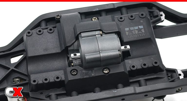
Secure the transmission with the four screws (two 12mm, two 25mm). This is a shot from under the chassis to see where the screws go (note the color difference – 12mm screws are light, 25mm screws are dark).
Chassis together, transmission installed. Quite a few screws and nuts in this assembly, but your CC-02 is starting to look pretty good.
Set your chassis assembly aside and let’s get to Part 3 – the Driveshafts.
Tamiya CC-02 Trail Truck Online Build – Part 3
The Tamiya CC-02 uses sliding propeller shafts to transfer power from the gearbox to the front and rear axles. They are both of equal length and use metal ‘balls’ for extra strength.
Build Notes:
Some patience is required here – getting the pins in the plastic parts can be a little tedious. If you use pliers (like the manual suggests), be extra careful not to snap the plastic.
Step 1:
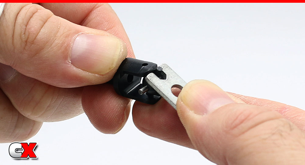
To get the balls into the female-side shafts, I used an old turnbuckle wrench I had laying around. Saves the fingers for sure! Make two of these.
Step 2:
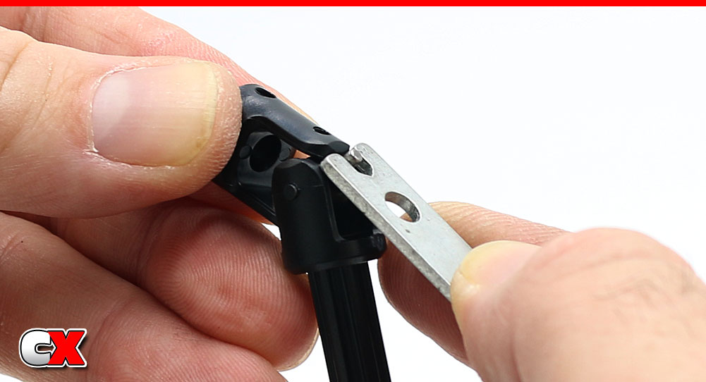
Using the same process, press the pins of the ball into the male-side shafts. Make two of these.
Step 3:
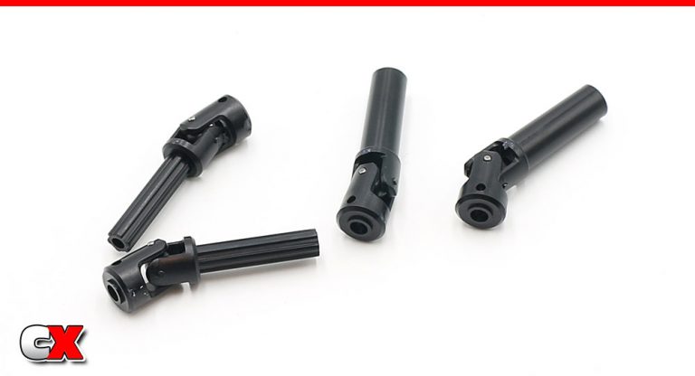
Your completed shafts, ready to install.
Step 4:
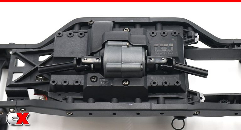
Slip the male-side shafts onto the transmission outdrives and secure with the 2.4x11mm screw pin. Set the female-side shaft aside for a later step.
Step 5:
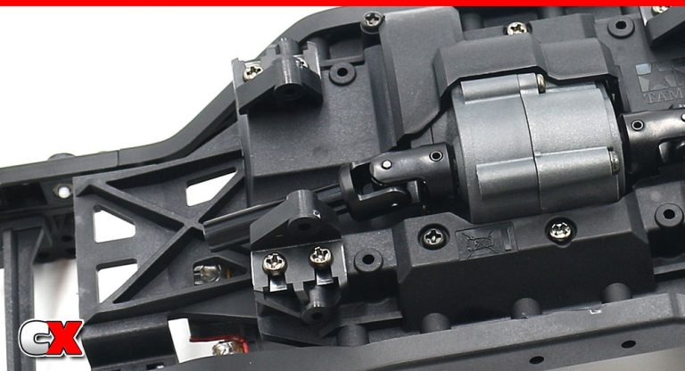
While we’re here, go ahead and install the inner link mounts. These are on the front.
Step 6:
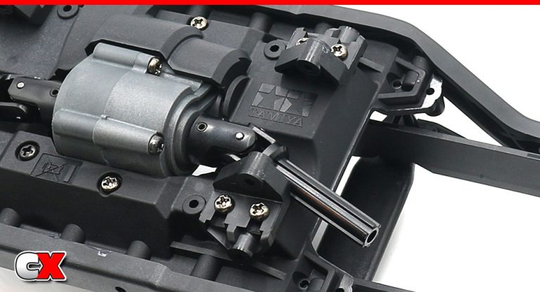
Inner link mounts on the rear.
Step 7:
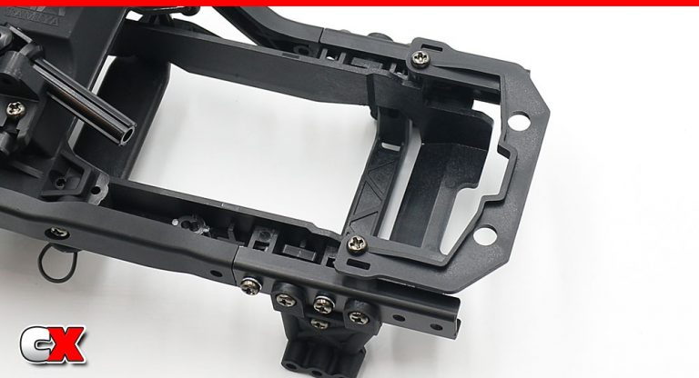
Finally, attach the quick-release battery mount.
Easy step, right?
Let’s move on to Steps 4 and 5 – the front and rear axles.
Tamiya CC-02 Trail Truck Online Build – Part 4
Unlike the original CC-01, the Tamiya CC-02 now comes with a solid front axle that can be built with either an open or locked differential. This can be changed to alter the way the truck steers and climbs.
Build Notes:
As mentioned above, you can build the diffs either open or locked. Parts to build it either way are included in the kit.
There are some small 3mm nuts that need to be installed INTO the axle housing before you assemble it. Don’t forget these.
Step 1:
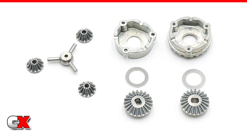
Before we begin, I want to point out the parts included to build an open diff. Unfortunately, this is not a sealed differential – any fluids will seep out almost immediately.
Step 2:
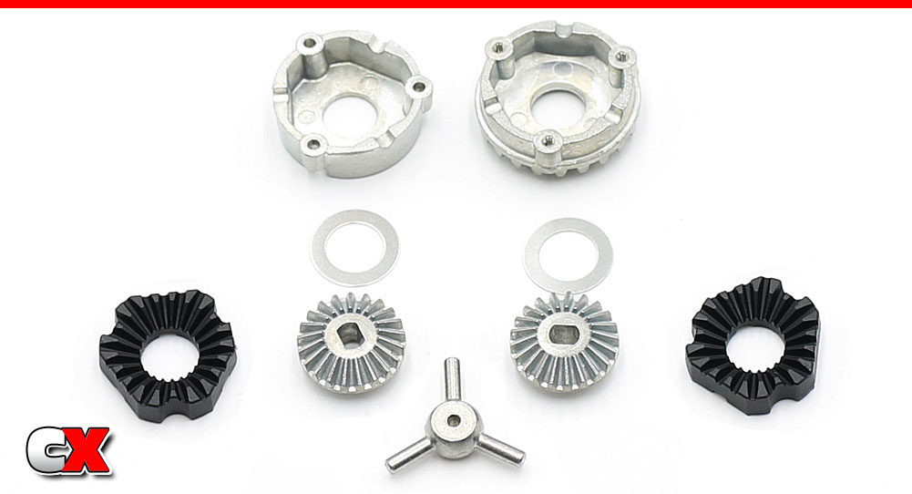
Here are the parts to build a locking differential – also included with the kit. I’ll be using these to build my CC-02.
Step 3:
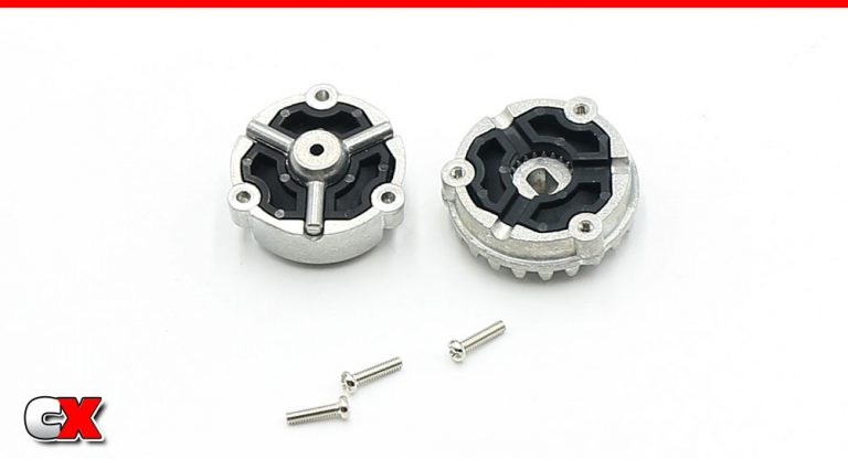
Set the 9mm washer into the diff housings followed by the large bevel gear. Now set the plastic diff lockers into place so the teeth of the bevel gears mate with the lockers.
Set the star shaft into place and mate the two diff halves together, securing with the 2x8mm screws (blue threadlocker is suggested here).
Step 4:
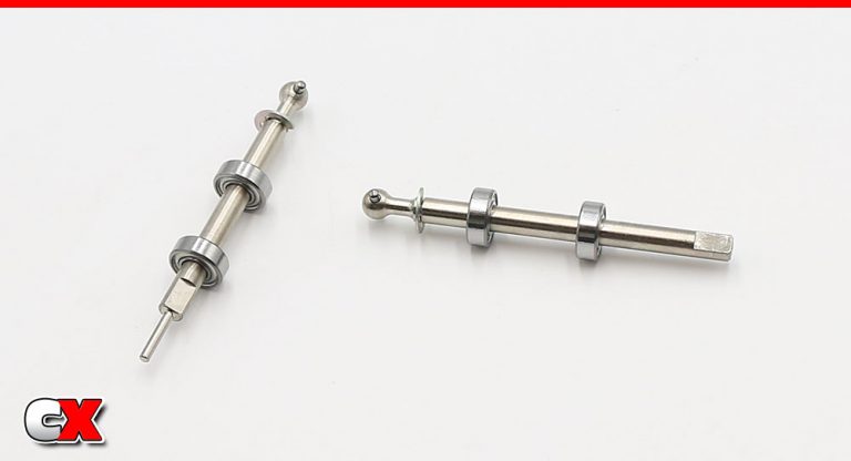
Assemble a pair of front axles; e-clips on the shafts followed by a pair of bearings.
Step 5:
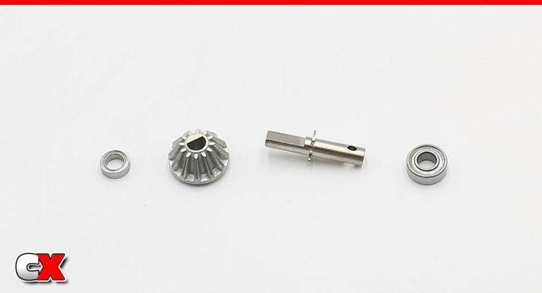
Assemble an output shaft; e-clip on the shaft, small bevel gear in place and two bearings.
Step 6:
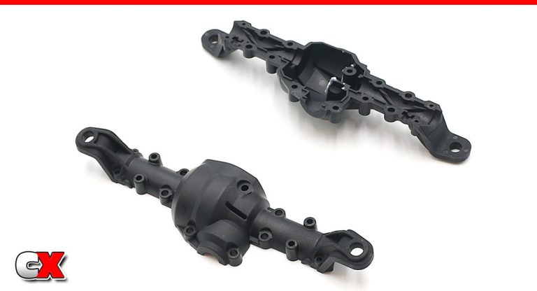
The top and bottom axle housings are different. Note the orientation.
Step 7:
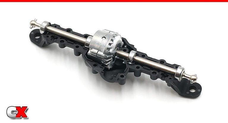
Slide the axles into the differential, then set that assembly into the bottom axle housing. You will need to slide the bearings on the axles to seat them in the bearing buckets in the axle housing.
Step 8:
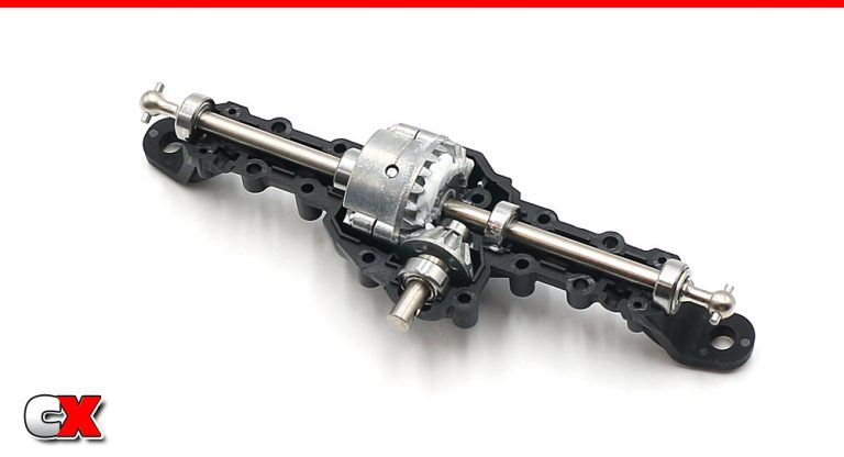
Set the output shaft assembly into place. Apply a liberal amount of grease and rotate to fully coat the gears.
Step 9:
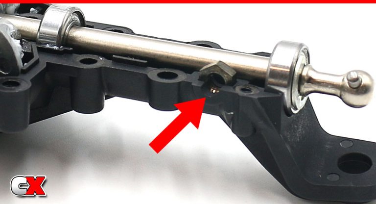
Set a 3mm nut into the pocket on the axle housing. You’ll need to insert one on both ends.
Step 10:
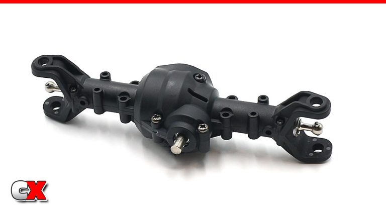
Mate the two axle housing halves together and secure with the seven screws. Note the size difference (both length and width) on all the screws.
Step 11:
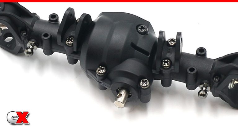
Attach the upper link mounts to the top of the completed axle assembly. Note that they are directional and labeled with an A and B.
You can also install the lower, 5mm shock ball connectors to the axle.
Step 12:
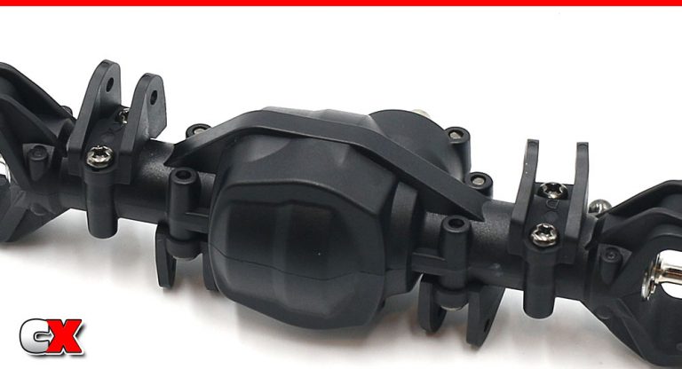
Flip the axle over and attach the lower link mounts. These are also directional and labeled with a C and D.
Step 13:
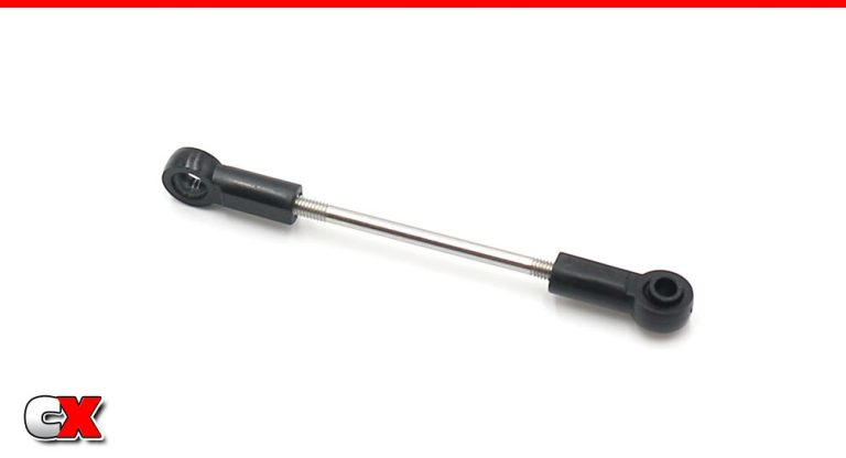
Build a steering drag link. Note that only one side receives a plastic ball.
Step 14:
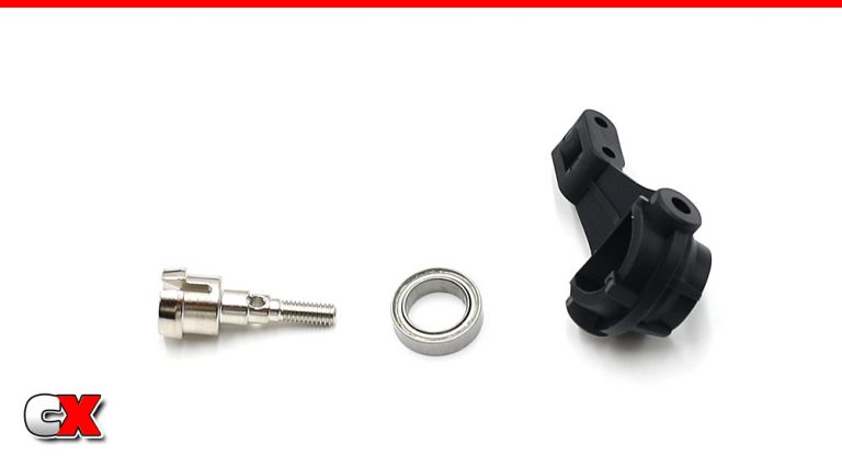
Press a large bearing into the steering arm, making sure it is fully seated. Slide the wheel axle into the bearing.
Step 15:
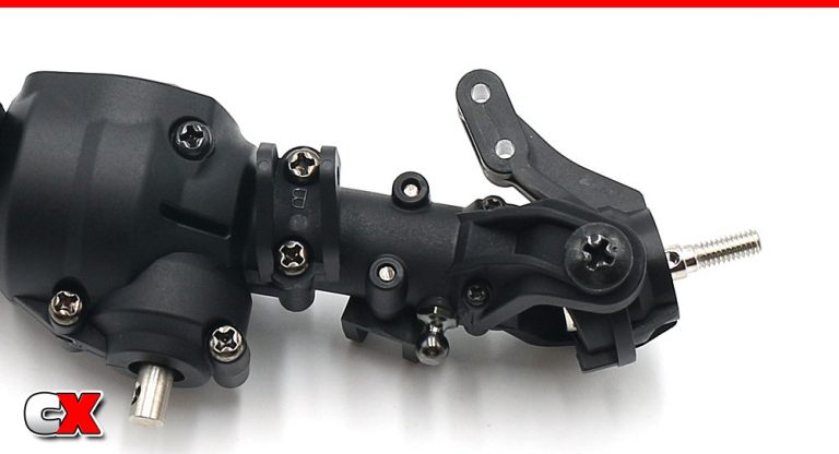
Slide the steering arm assembly into place, making sure to key the wheel axle to the dog bone. Secure with the two large step screws.
Note the orientation of the steering arm; the arm itself should be towards the front of the axle (away from the output shaft).
Step 16:
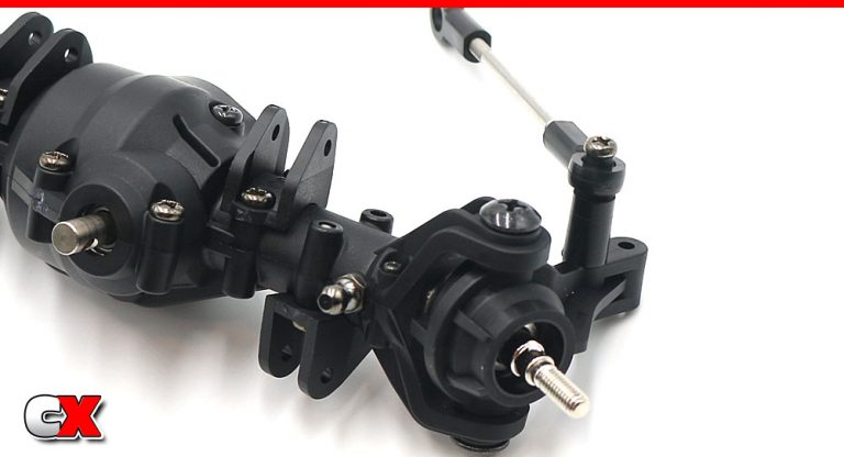
Feed the 3x27mm screw through the steering drag link, the tall spacer and into the inner hole on the steering arm. Do not overtighten.
Step 17:
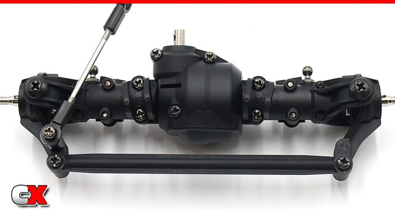
Attach the plastic steering link to the outer hole on both the left and right steering arms.
Step 18:
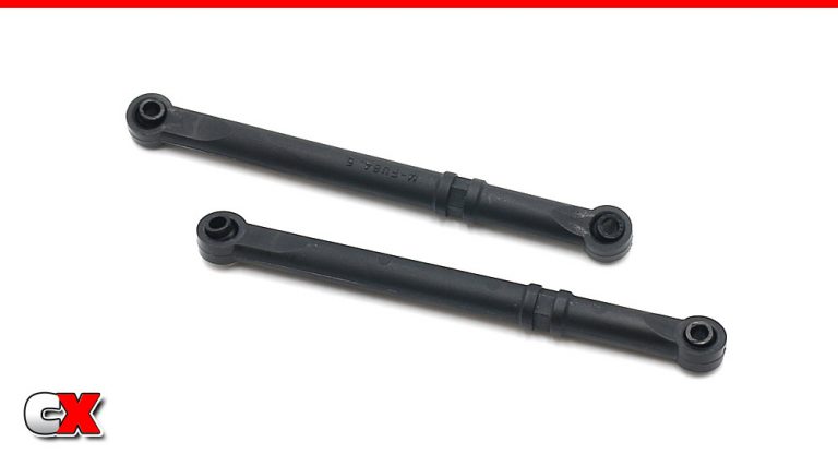
Build a pair of short upper links…
Step 19:
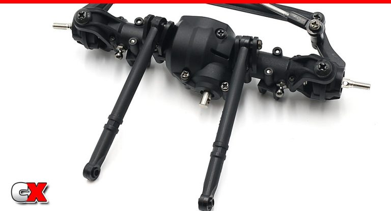
…and attach to the top of the axle housing.
Step 20:
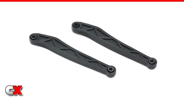
Build a pair of short lower links…
Step 21:
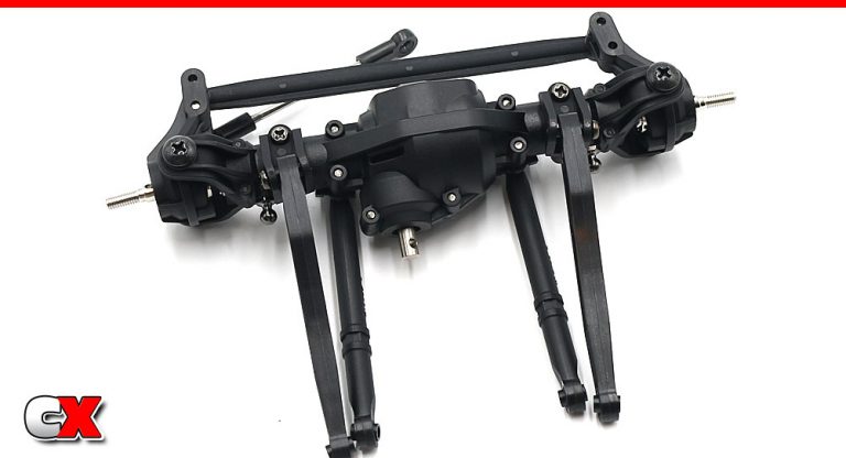
…and attach to the bottom of the axle housing. Note the orientation of the links.
Step 22:
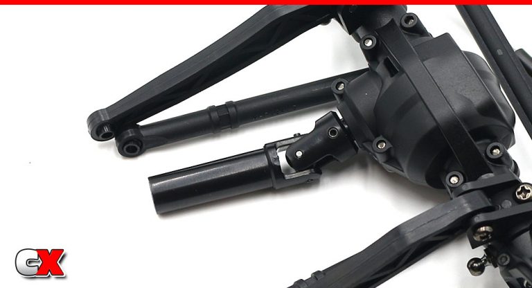
The last step is to install the male-side driveshaft to the axle.
Nice job on the front diff. Hopefully you didn’t have to pull it apart to re-install those 3mm nuts! 🙂
Alrighty – on to the rear diff!
Tamiya CC-02 Trail Truck Online Build – Part 5
The rear axle on the Tamiya CC-02 is similar to the front. It can be built with an open or locked diff, uses hidden M3 nuts and has the link mounts (and links) attached the same way.
Build Notes:
Like the front axle, you can build the diffs either open or locked. Parts to build it either way are included in the kit.
M3 locknuts are captured inside this housing as well.
When mating the driveshafts, make sure the ‘screw pins’ are lined up with each other. This provides a smoother rotation in the drivetrain. See Steps 14 and 15 for more details.
Step 1:
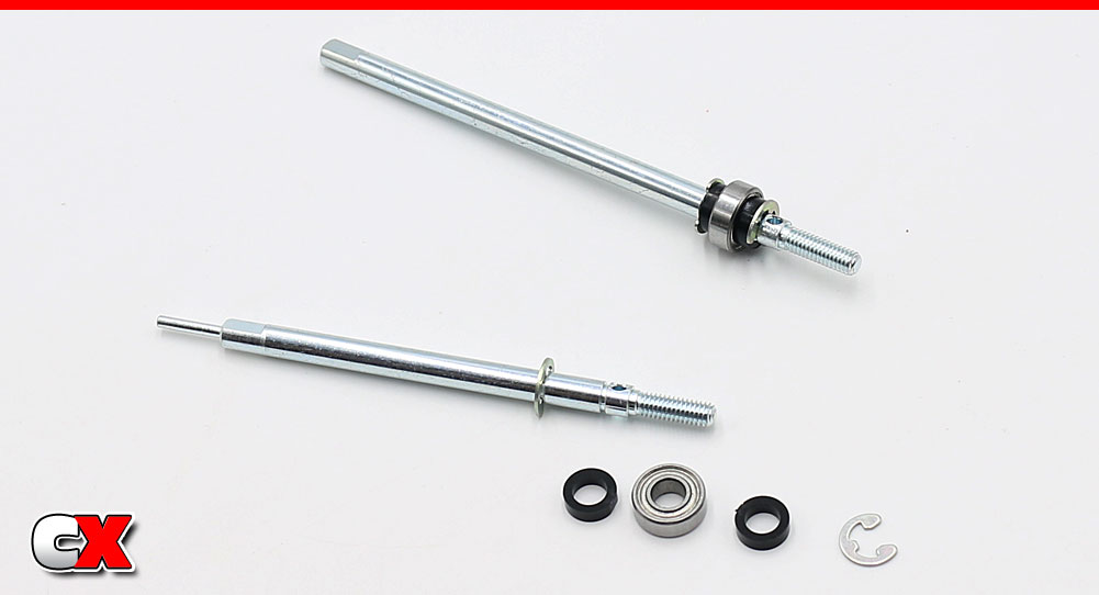
Build the pair of rear axles; e-clips onto the shafts followed by a plastic spacer, the bearing, another plastic spacer and another e-clip.
Step 2:
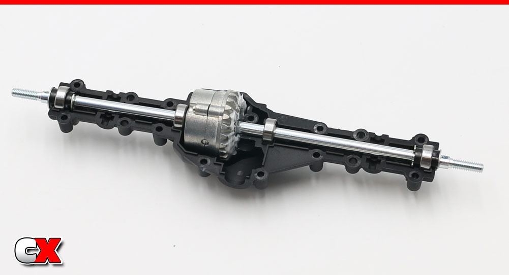
Build the rear differential like the front; I’m locking this one as well. Slide another bearing onto the axles, slip the pair of axles into the diff and set that whole assembly into the lower axle housing. Again, you’ll probably need to move the bearings back or forth to get them into the bearing buckets.
Step 3:
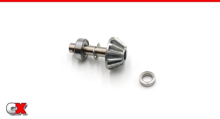
Assemble the output shaft (just like the front).
Step 4:
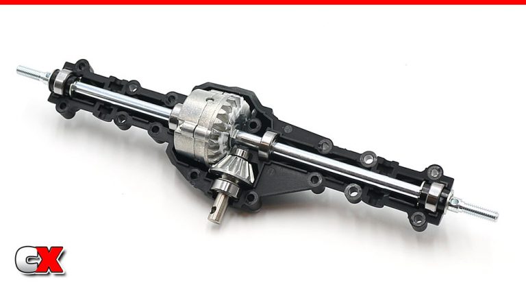
Set the output shaft into place and add a liberal amount of grease. Rotate the gears to spread the grease.
Step 5:
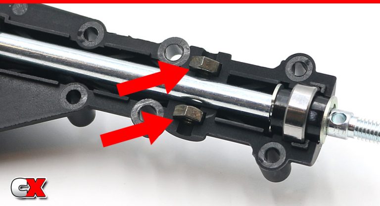
On this axle, we’ll need 3mm nuts of both sides of the axle – 4 in total (two on the other side as well).
Step 6:
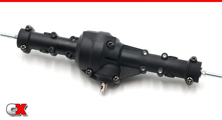
Mate the two axle housing halves together and secure with the seven screws.
Step 7:
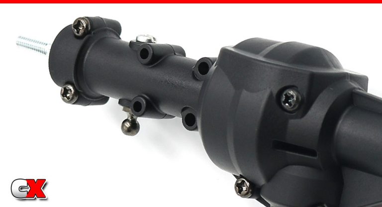
Insert a 5mm ball connector and 3x4mm screw into the holes on the axle housing as shown.
Step 8:
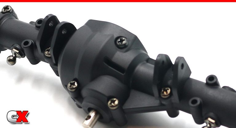
Attach the top link mounts. Like the front, these are marked with an A and B.
Step 9:
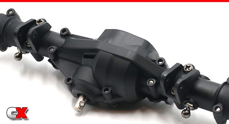
Flip the axle and attach the lower link mounts (marked with a C and D).
Step 10:
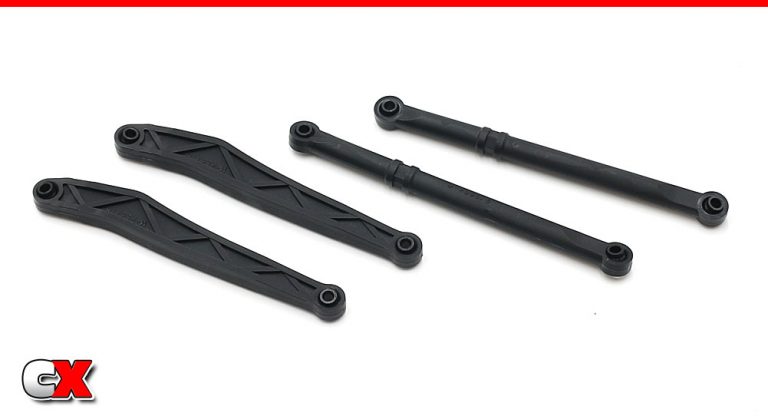
Build a pair of the longer, upper and lower links.
Step 11:
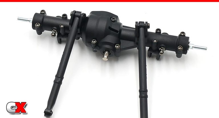
Attach the upper links.
Step 12:
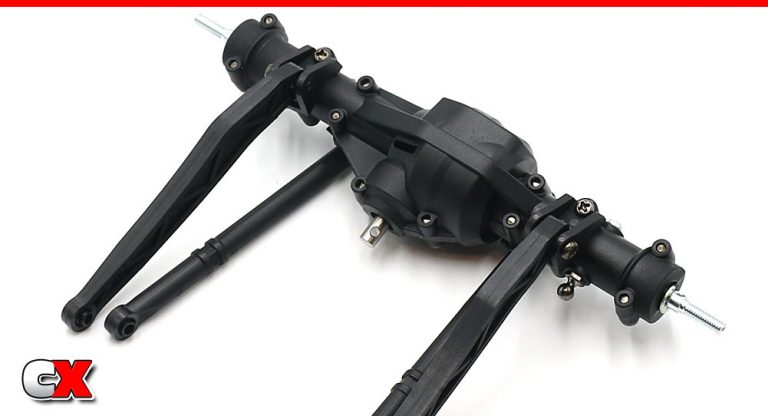
Attach the lower links. Note the orientation.
Step 13:
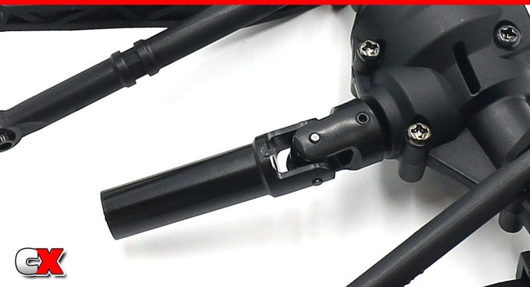
Attach the male-side driveshaft to the axle.
Step 14:
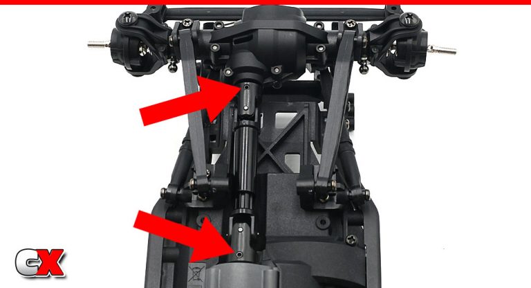
Starting with the driveshafts, attach the front axle assembly to the chassis. Note the red arrows – they show the input shaft screw pins lining up with each other.
Attach the links to the link mounts.
Step 15:
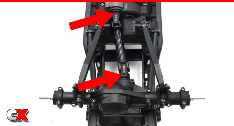
Starting with the driveshafts, attach the rear axle assembly to the chassis. Note the red arrows – they show the input shaft screw pins lining up with each other.
Attach the links to the link mounts.
Axles done and attached!
She’s lookin’ like a real rig now! Time to work on Part 6 – the Shocks.
Tamiya CC-02 Trail Truck Online Build – Part 6
The shocks on the Tamiya CC-02 are pretty basic – plastic bodies with ride height clips, internal bladder, dual o-ring lower cartridge and a one-piece piston/shock shaft plunger. While not amazing, they’ll certainly get the job done.
Build Notes:
With any shock build. you’re going to want to have a shock stand (to hold the shocks) and plenty of paper towels (to clean up any mess).
Step 1:
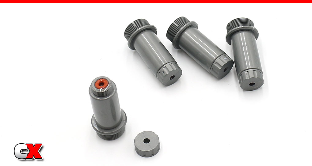
The first step is to press a pair of red o-rings into the bottom cartridge area. I added a drop of 20wt oil (that’s what I’ll be using in the shocks). Build 4.
Step 2:
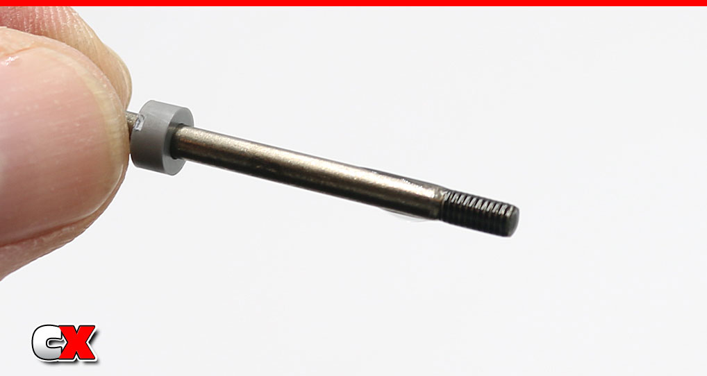
Add the X11 spacer to the shaft, then place of drop of oil on the threads of the shock shaft.
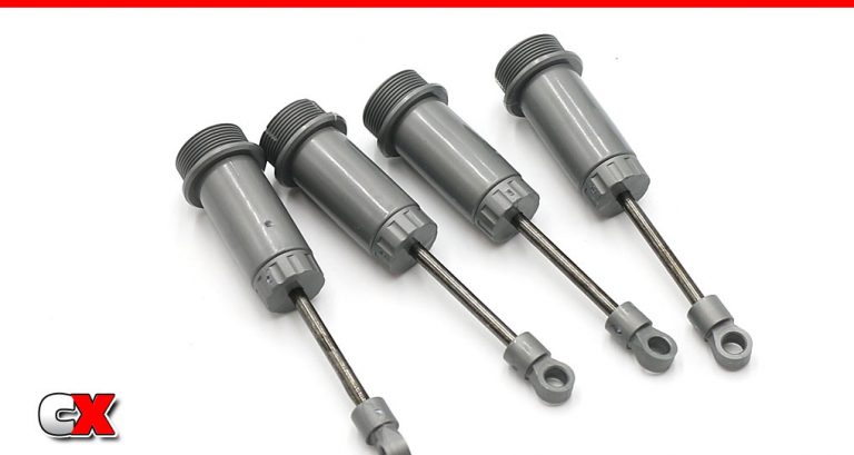
Step 3:
Slide the shaft through the body and cartridge and, once through, add the short shock rod end. Plunge the shaft a few times to spread the oil onto the internal o-rings.
Step 4:
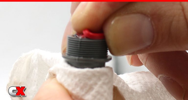
Fill the shocks with oil and plunge the shaft a few times (slowly) to release any bubbles from under the piston. Place in your shock stand and move on to the next shock. Build 4.
Once completed, move back to the first shock and check to see if the bubbles have fully dispersed. If they have, add a little more oil and then install the red bladders. Place the bladder on the shock and ‘roll’ it into place. This will force any excess oil out of the shock. Screw the shock cap on and use your paper towels to clean any excess oil off the shocks. Build 4.
Step 5:
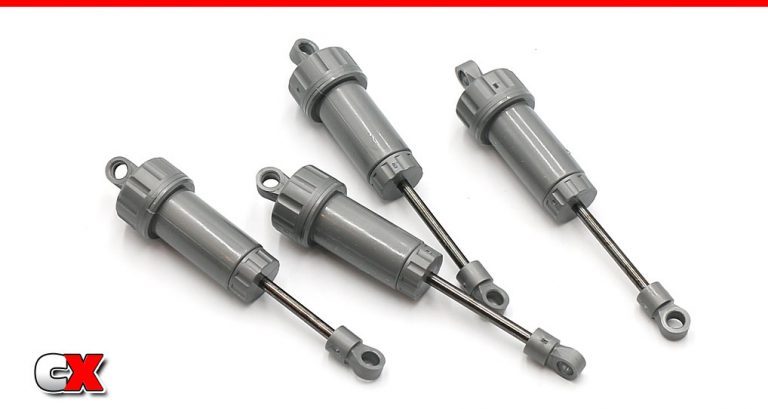
Semi-completed shocks, all cleaned up.
Step 6:
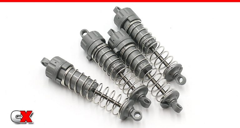
Add the X7 ride height spacer, the spring and the lower spring retainer to all 4 shocks.
Wah-lah – pretty little shocks, all in a row.
Step 7:
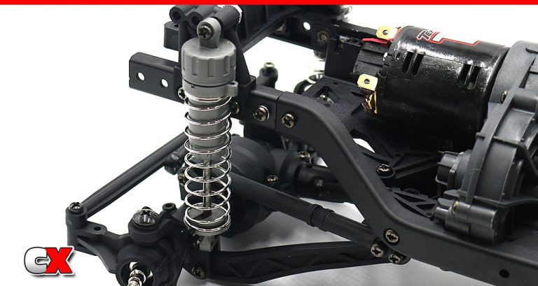
On the front, attach the shock to the rear-most shock hole with the 3x20mm screw, 3x6mm spacer and 3mm flange nut. Do not overtighten – just nice and snug.
Pop the lower part of the shock onto the 5mm ball connector on the axle.
Step 8:
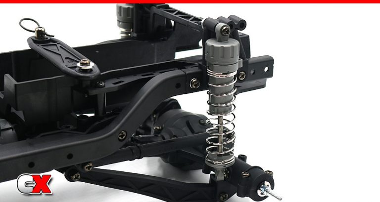
On the rear, attach the shock to the front-most shock hole with the 3x20mm screw, 3x6mm spacer and 3mm flange nut. Do not overtighten – just nice and snug.
Pop the lower part of the shock onto the 5mm ball connector on the axle.
Great job on the shocks. Work the suspension a little to make sure there is no binding.
Set your CC-02 aside, grab your running gear and let’s head to Part 7 – the Electronics.
Tamiya CC-02 Trail Truck Online Build – Part 7
The Tamiya CC-02 comes with the TBLE-02S ESC and Mabuchi brushed motor. If you choose to swap those parts out, know that almost any electronics will work; full-size servo, 540 motor, standard ESC and receiver. The CC-02 is even designed to work with typical LiPo batteries – no more shotgun-only packs!
Build Notes:
While the receiver box is not waterproof, it will protect it from dust or splashes. If you’re set on a full waterproof setup, you can probably add a bead of silicone between the case and lid to seal things up.
It’s always a good idea to test your electronics prior to installation (as well as center the servo). However, it’s good to know that you can easily get to the servo horn to reset the servo if it becomes offset.
The CC-02 comes standard with Tamiya’s TLU-01 LED Light Unit. While I will be using this, I won’t be showing it installed in this build.
Unfortunately, the Tekin ESC hasn’t shown up yet, so I won’t be showing that in this build either.
Step 1:
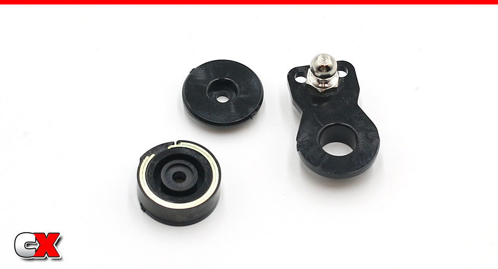
Let’s start off with building the servo saver. If you’ve had Tamiya cars before, you’ll recognize this thing right away.
Slip the two chrome clips into place followed by the black clip. This does require some pressure to settle them in place.
Attach the 6mm ball connector to the servo horn.
Step 2:
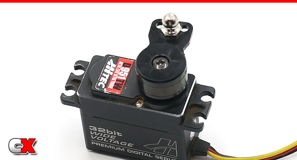
Attach the servo horn to your servo. Note the orientation – I am installing the servo with the output shaft facing down. If you’re installing with the output shaft facing to the front, it will look different.
Step 3:
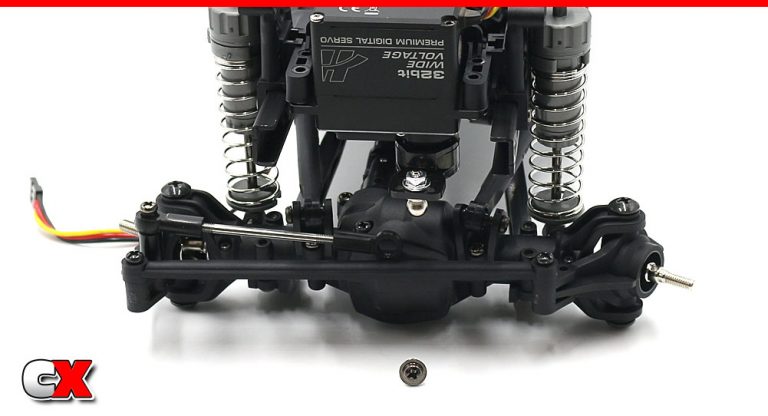
Attach the servo to the mount using the two 3x10mm flange tapping screws.
Step 4:
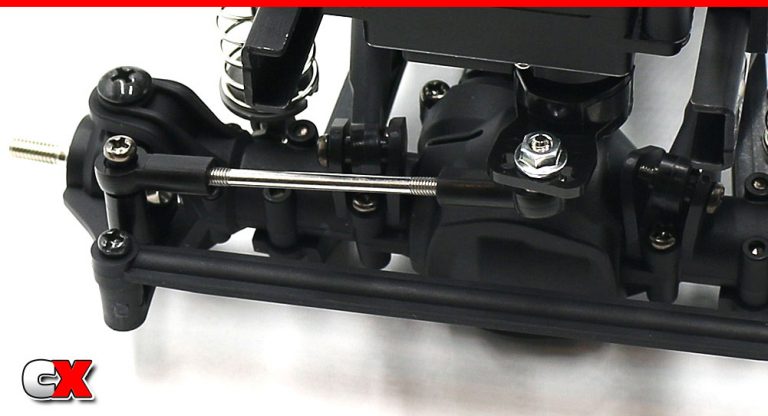
Pop the steering link onto the 6mm ball connector.
Step 5:

Attach the electronic mounting pads to both sides of the CC-02.
Step 6:
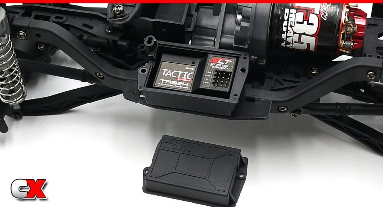
Using the provided double-sided tape, attach the receiver box to the right side of the chassis. Install your receiver and route your servo and ESC wires into the back of the box.
Secure the lid with the two 3x8mm screws.
I’m sure, by this time, you’ve already installed a battery and fired up the electronics. Bet you can’t wait to get this rig outside!
Find job! Only 1 step left – Part 8 – the Final Steps.
Tamiya CC-02 Trail Truck Online Build – Part 8
Wrapping up the Tamiya CC-02 build, we’ll be installing the front and rear bumper, body mounts and wheels and tires. Again, the body wasn’t quite done for this build so we’ll be skipping that until a later time.
Build Notes:
While the kit says not to glue the wheels to the tires, I find that they fall off a lot less if they are glued. CA glue is the way to go, just be careful with it!
Step 1:
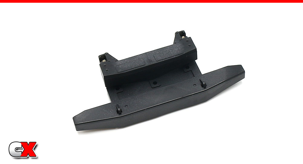
Assemble the front bumper…
Step 2:
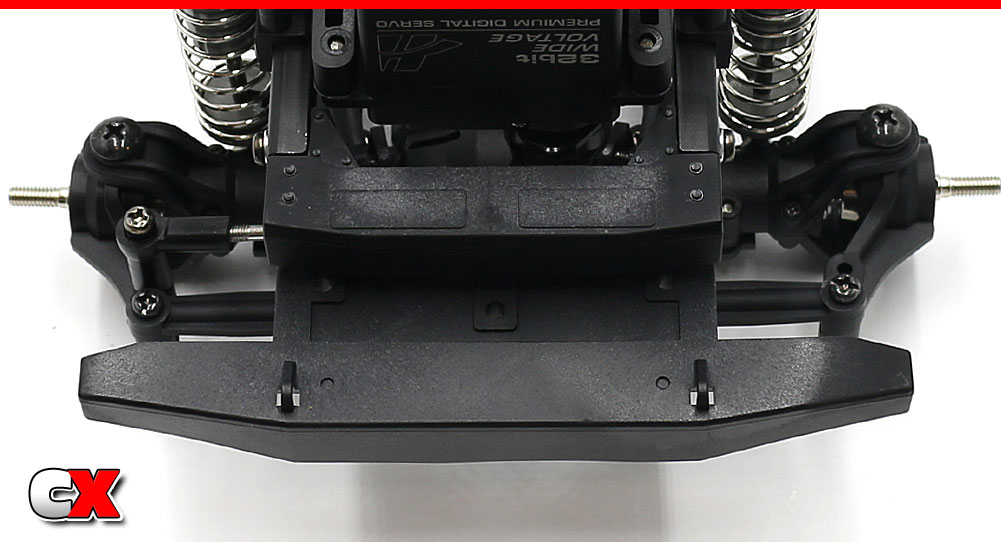
…and attach it to the CC-02.
Step 3:
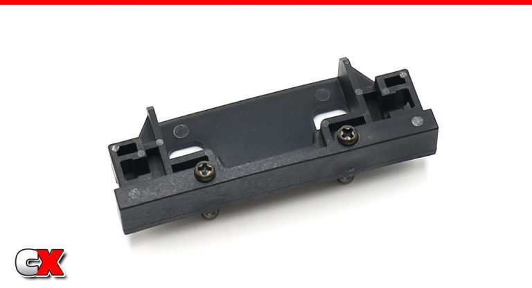
Assemble the rear bumper.
Step 4:
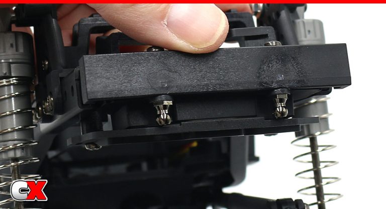
Key the rear bumper to the aluminum frame rails. Bend down the plastic quick-release battery tray and slide the rear bumper into place.
Tamiya has provided this optional quick-release function but I can only imagine it working if you had a body that didn’t have a back to it.
Step 5:
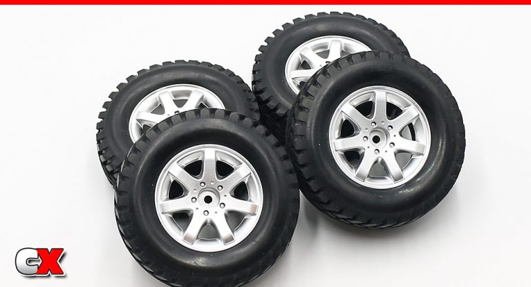
Fit the tires to the wheels. As mentioned before, the manual states not to glue them together, but that just doesn’t make sense to me. I say do it.
Step 6:
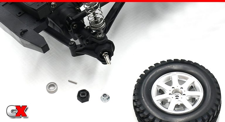
Press a bearing onto the front axle, then insert a 10mm pin into the hole in the axle. Slide and key the plastic wheel hex to the pin.
Attach the tire and secure with the 4mm flange lock nut. Complete both sides.
Step 7:
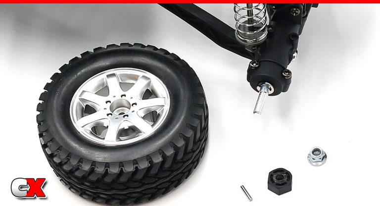
Moving to the rear, slide a 10mm pin into the hole in the axle followed by the plastic wheel hex (key this to that pin).
Attach the tire and secure with the 4mm flange lock nut. Complete both sides.
Step 8:
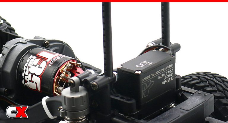
Attach the front body mounts.
Step 9:
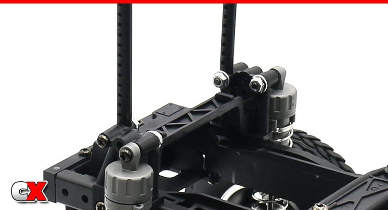
Attach the rear body mounts.
Step 10:
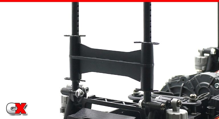
Last, but not least, install the rear body mount support.
And that’s it – you’ve completed the build of your Tamiya CC-02 chassis! All that’s left is to wrap up the body and you’re ready to hit the trails!

