
Tekno ET410 Online Build
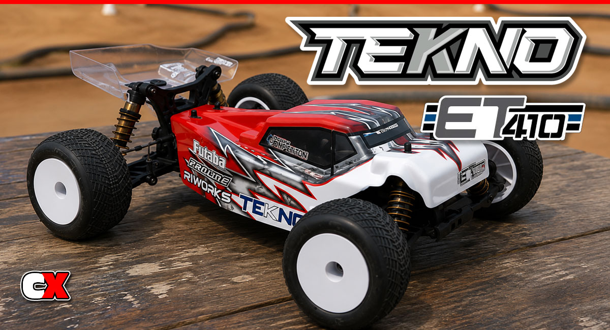
It’s no secret that Tekno is rising to the top of the competitive RC heap – quality products, extremely durable and man do they perform! Even with all that going for them, the San Diego plant is still popping out some surprises … enter the ET410, a 4WD 1:10 scale Stadium Truck (or Truggy). This was certainly not something people were expecting, but it has created a HUGE boom that is being well received.
We were lucky enough to get one of these trucks to do a build and review with, so let’s get right to the build first. If you saw the build of the Tekno EB410 (here:
https://www.competitionx.com/tekno-et410-online-build/), you’ll see that most of the process is about the same. That’s because Tekno has made the EB410 (buggy) and ET410 (truck) compatible with 95% of it’s parts. Great news for those wanting to run both 4-wheel classes without having to carry twice as many parts!
Tekno ET410 Online Build – Part 1
Tekno’s ET410 comes equipped with 3 high-quality fluid-filled gear differentials. The front and rear use steel gears while the center (spur gear) comes with a strong molded plastic gear.
Build Notes:
• In this step we’ll be working with greases and diff fluids. Be prepared with some clean rags or towels to help clean up any mess.
• We’ll be building 3 differentials, all of which go together almost exactly alike. The first one will be a detailed walkthrough, the other two more of a refresher. If you have any issues with the latter 2, just refer back to Steps 1-7.
Pre-Build:
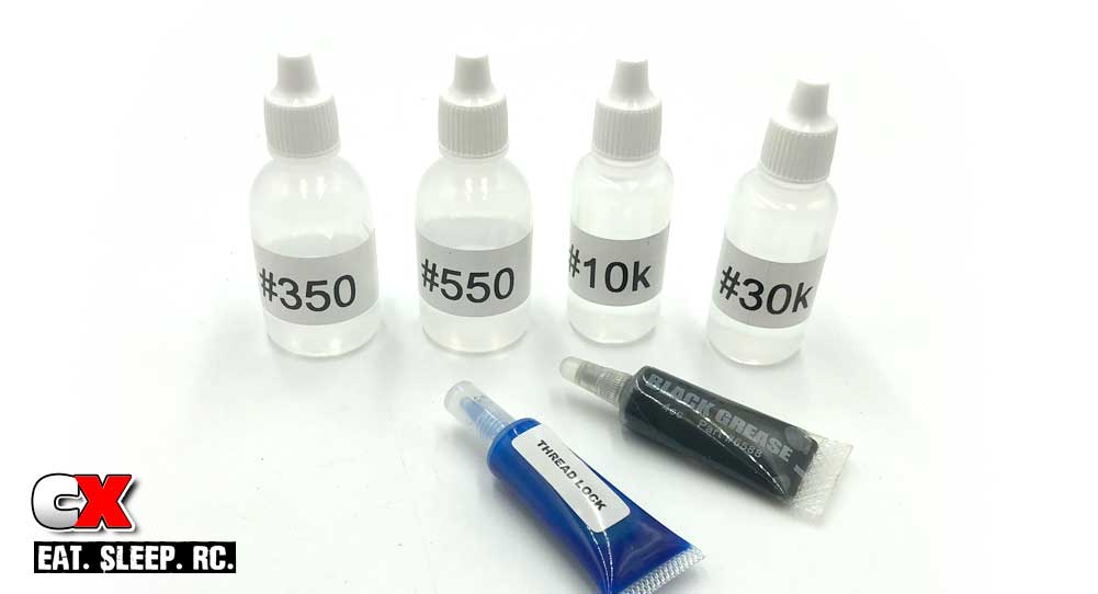
Before we get into the build, let’s take a quick look at the fluids Tekno supplies in the box. There are 4 small bottles: #350, #550, #10K and #30K. The #350 and #550 (aka 30wt/50wt) are used for the shocks; you can set those aside for now. The #10K and #30K are for the differentials and used in this step.
Tekno also includes a tube of Threadlocking compound and Black Grease. You might just want to keep these handy as well.
Step 1:
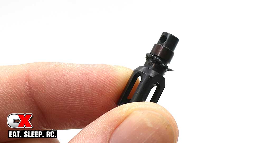
The first thing we need to do is apply a small bead of black grease to the groove on one of the outdrives as shown. More is better than less here.
Step 2:
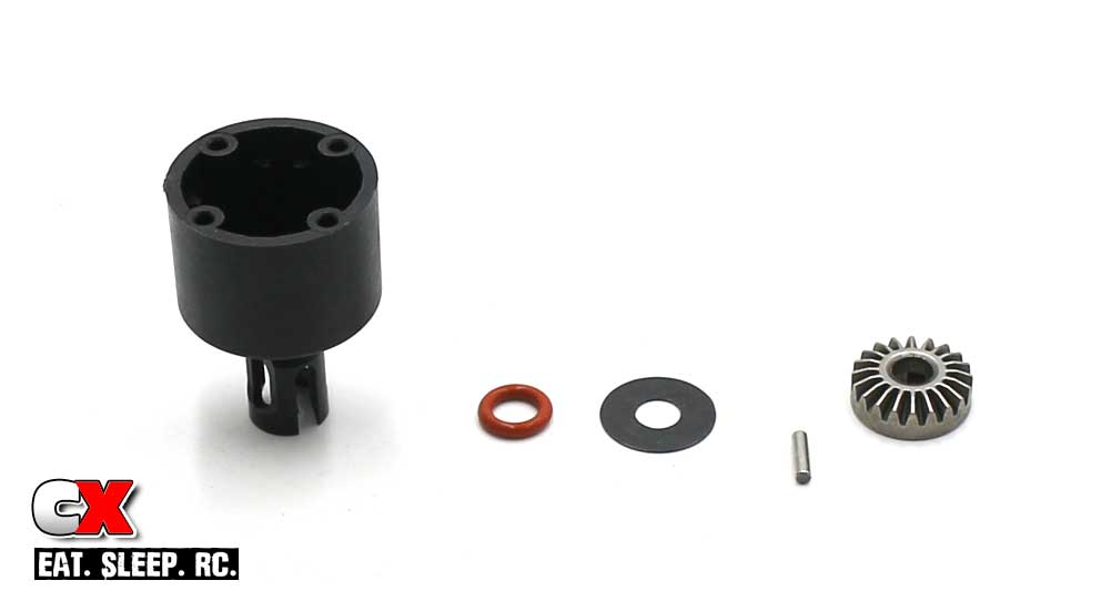
Slide the outdrive through the diff housing from the outside, then (from the inside) create a small bead of black grease around the outdrive. Slip the red o-ring and washer over the outdrive and press down until the washer is flat with the bottom of the diff housing. Slide the drive pin through the hole in the outdrive, then key the satellite gear to the drive pin.
Step 3:
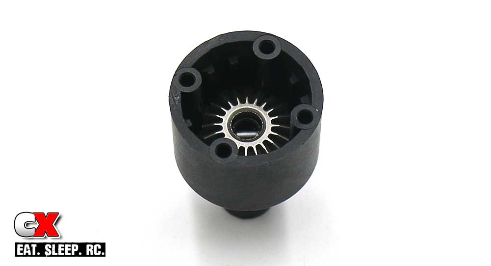
Your completed assembly should look like this.
Step 4:
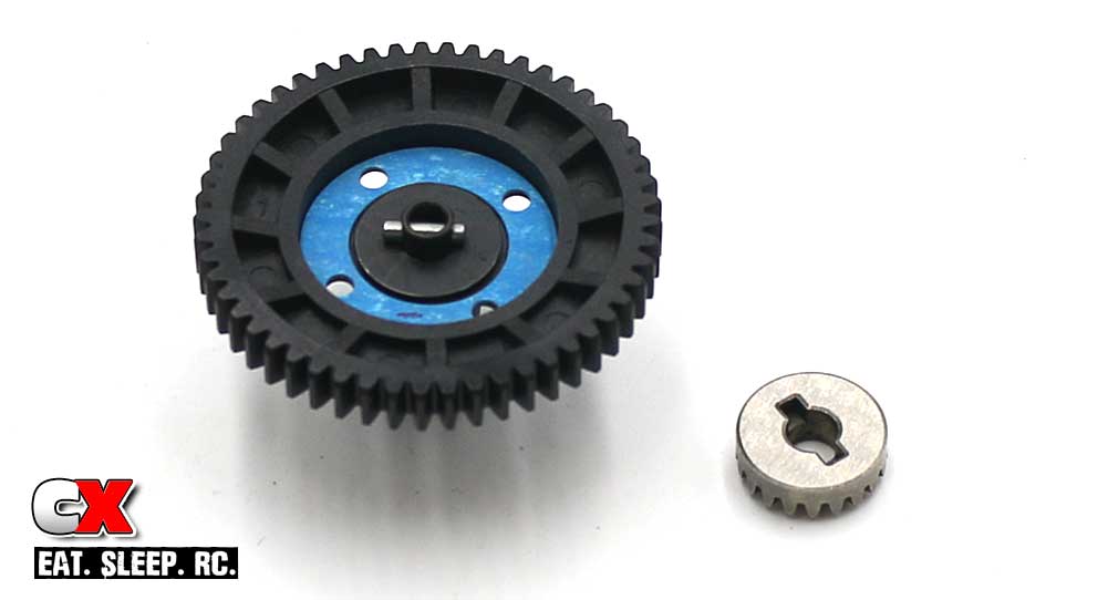
Grab another outdrive and apply a bead of black grease to the groove (as you did in Step 1). Press it through the diff gear, then apply another small bead of black grease followed by the red o-ring, washer and drive pin. Slip the blue diff gasket into place, making sure the holes in the gasket line up with the holes in the diff gear. Finally, slip the satellite gear into place, keying it to the drive pin.
Tech Note: To help keep the satellite gear in place, add a smidge of black grease to the drive pin.
Step 5:
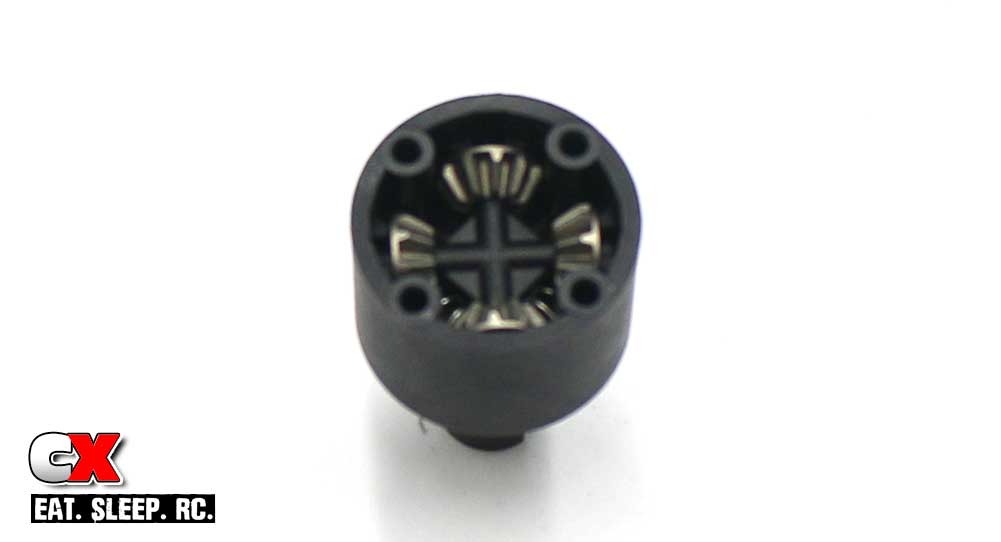
Build the smaller satellite gear assembly and drop down into the diff housing. Give the outdrive a slight turn to make sure all of the gears are correctly meshed.
Step 6:
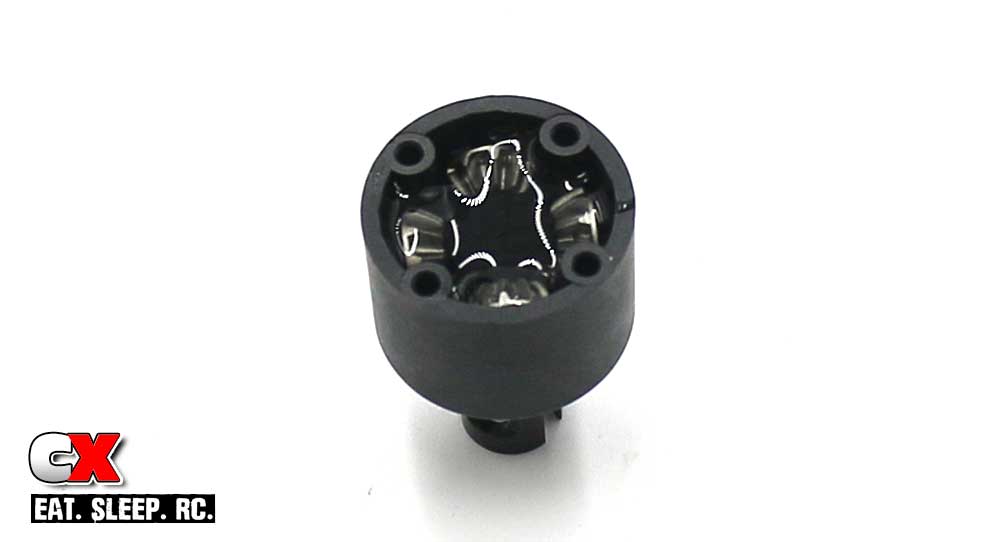
Grab the #30K diff fluid and fill up the housing to just above the satellite gears. Let it sit for a few minutes, then double check it. Most likely the fluid will have seeped and settled, leaving the fluid height below the top of the satellite gears. Refill (if necessary) to just above the top of the satellite gears.
Step 7:
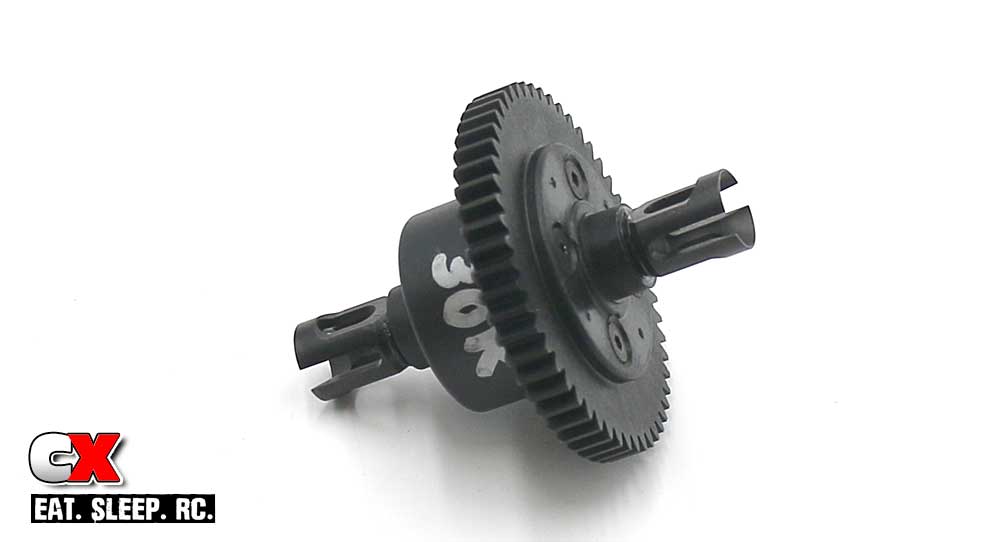
Mate the two diff halves together and, while pressing together, rotate one outdrive to make sure the gears inside mesh correctly. Once completely pressed together, secure with the M2.5x10mm screws.
To keep track of what fluid is in the diff, write it on the outside with a silver Sharpie.
Step 8:
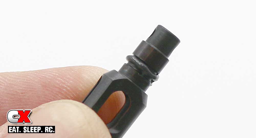
On to the front and rear diffs. Again, these build almost exactly like the center diff, so this part of the build will be a little more condensed.
Apply a bead of black grease to the groove in one of the outdrives.
Step 9:
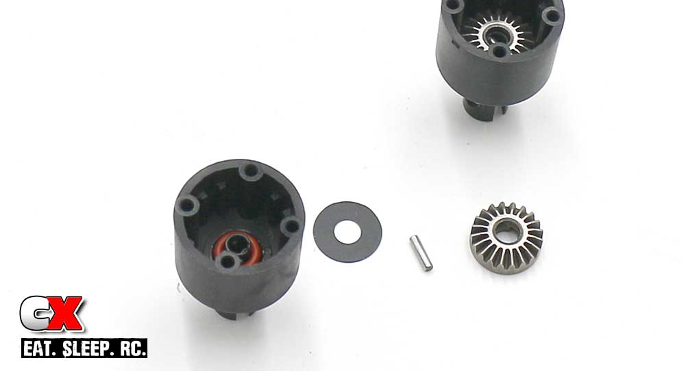
Slide it through the housing, add another small bead of black grease, insert the red o-ring, washer, diff pin and satellite gear.
Step 10:
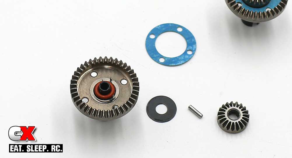
Grease the groove on another outdrive, slide into the steel outdrive gear, more grease, red o-ring, washer, diff pin and satellite gear. Don’t forget to press the blue gasket into place and line up the holes.
Step 11:
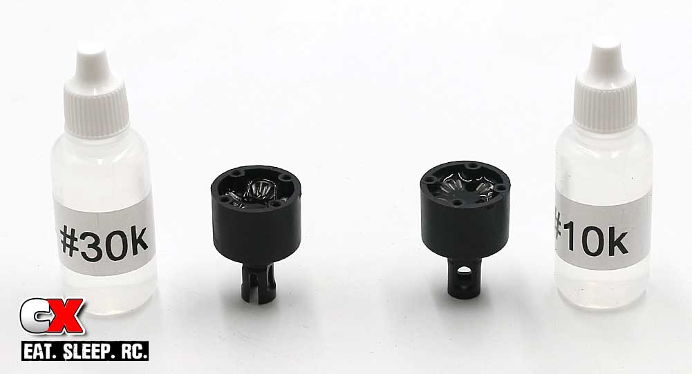
Build the smaller satellite gear assembly and slide into the diff housing (don’t forget to check the mesh). In the front diff, fill it (like you did in Step 6) with #30K, the rear diff with #10K. Let them sit for a second and refill if necessary.
Step 12:
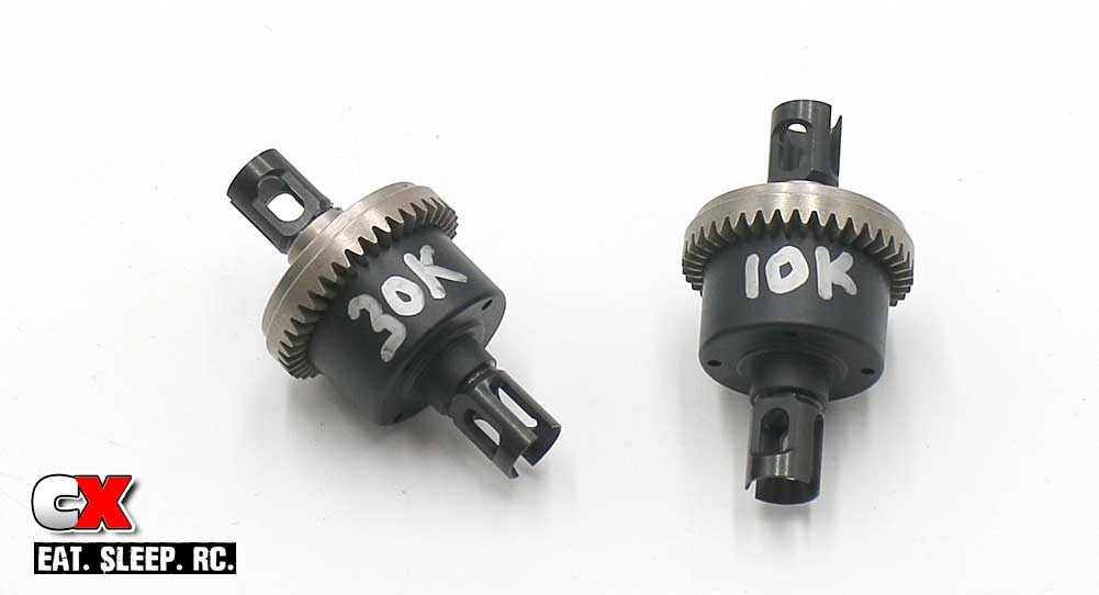
Finally, mate the two halves, check the mesh of the internal gears (as you did in Step 7) and secure with the M2.5x10mm screws. Make sure you write the correct fluid on the correct diff.
Clean up any excess fluid with a rag and some motor spray, set the diffs aside and let’s move on to the next step!
Tekno ET410 Online Build – Part 2
The next step in our Tekno ET410 build is the steering system and front bulkhead assembly. The ET410 uses a dual bellcrank steering setup that rides on a full set of bearings. The bulkheads are designed to completely encapsulate the diff, using molded plates on the bottom to seal everything up.
Build Notes:
• Pay special attention to Step 3; make sure the steering rack bushings are pressed COMPLETELY into the plastic steering bellcrank arms. If not, they could twist when tightening down the screw that feeds into them and strip out the plastic arms.
Step 1:
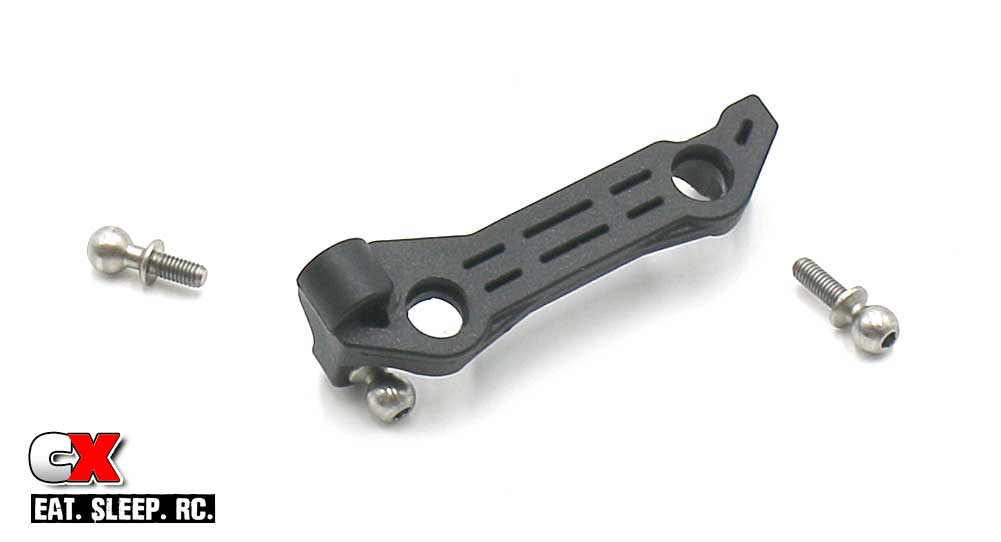
Attach the three ballends to the steering rack. Note that the two 8mm ballends attach on the same side; the 6mm ballend faces the opposite direction.
Step 2:
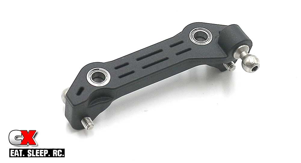
Press the bearings into the steering rack.
Step 3:
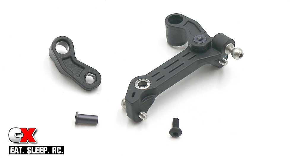
Slide the steering rack bushings into the bellcrank arms, making sure they press ALL THE WAY into place (see Build Notes). Use the M3x8mm screws to attach the bellcrank arms to the rack. A drop of the blue threadlocker is suggested here.
Step 4:
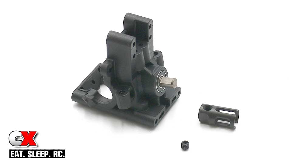
Press the bearings into the bulkhead, then insert the output gear into place. Slide the outdrive cup onto the output gear and secure with the M4x4mm set screw. Blue threadlocker is suggested here.
Tech Note: You want the outdrive cup to be as close to the bearing as possible without touching it; a teeny weenie gap is all you need.
Step 5:
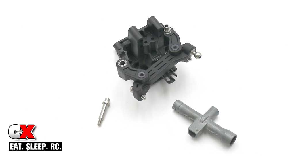
Attach the steering assembly to the bulkhead as shown. Do not overtighten; you don’t want any bind in the steering system.
The steering standoff posts require a 5.5mm driver to install; I happened to have one (of a couple hundred that I have) of my handy-dandy Tamiya wrenches sitting right by and used that.
Step 6:
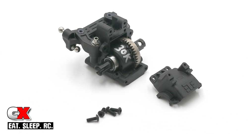
Grab your front diff (you did mark which diff is the front one, right?) and slide a 10×15 bearing on each side, the set that assembly into place within the diff housing. Apply a small bead of black grease to the gears. Capture it with the diff cap, held on by four of the M3x8mm screws.
Note the direction of the diff.
Step 7:
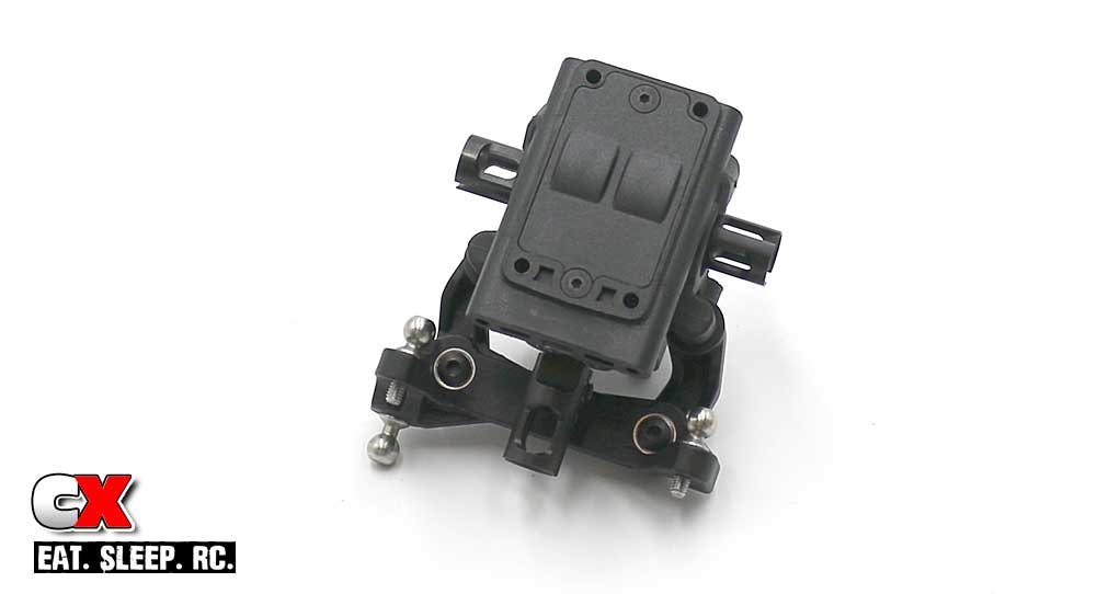
The final step is to attach the lower bulkhead cap, held in place with two M2.5x6mm screws.
Simple, easy step. We’ll see a similar process in the next step; the rear bulkhead.
Tekno ET410 Online Build – Part 3
In Step 3 of our Tekno ET410 build, we assemble the rear bulkhead; shock tower, camber link mount and body mounts.
Build Notes:
• In Step 7 we’ll be using CA glue to keep some locknuts in place. You’ll only need a small drop – be careful you don’t glue your fingers to the plastic!
Step 1:
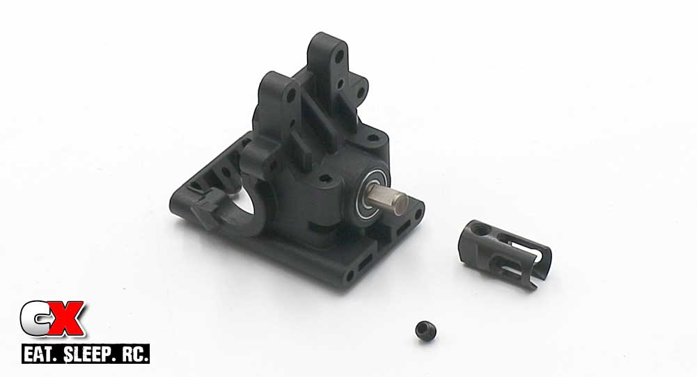
The rear bulkhead goes together much like the front; press the two bearings into place, slide the output shaft through and secure the outdrive with the M4x4mm setscrew. Blue threadlocker is suggested here.
Step 2:
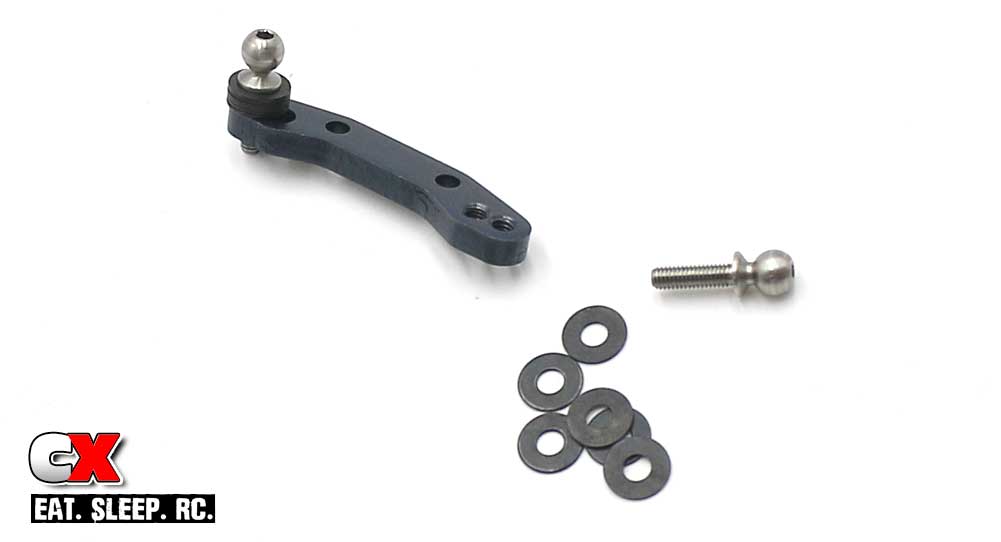
Using 6 of the shims, feed the 10mm ballstud into the mount. Blue threadlocker is suggested here.
Step 3:
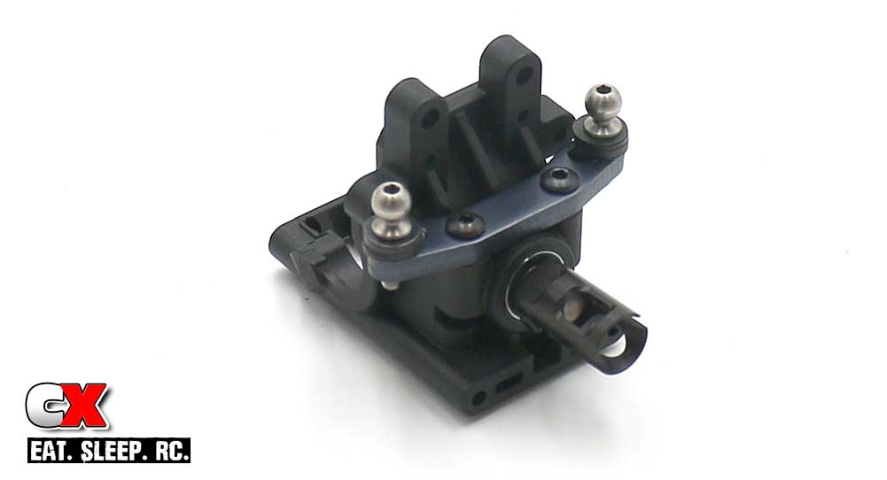
Attach your assembled camber link plate to the bulkhead.
Step 4:
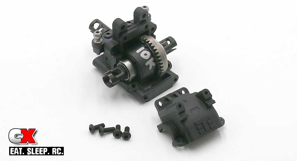
Grab your rear diff and slide a 10×15 bearing onto each side of it, then drop it into the bulkhead as shown. Make sure you put a light bead of black grease on the gears. Cap off the bulkhead and use the four 8mm screws to keep it in place.
Step 5:
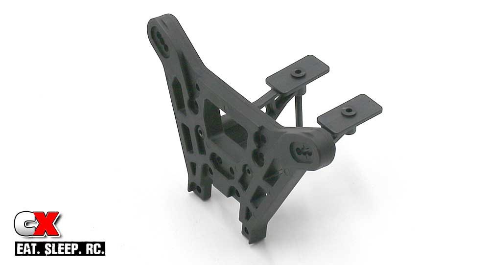
Attach the wing mounts to the rear tower. Note the orientation of the tower.
Step 6:
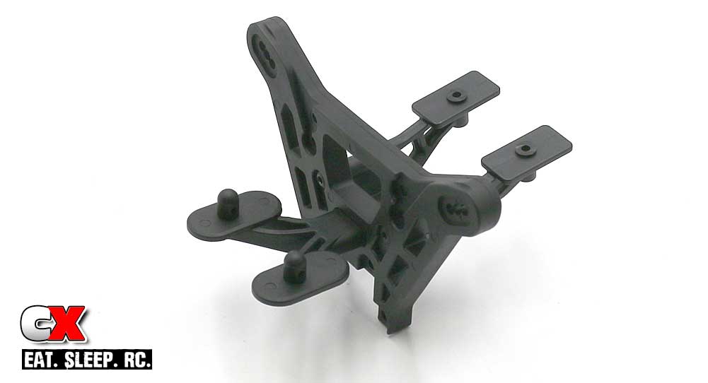
Attach the body mounts to the tower.
Step 7:
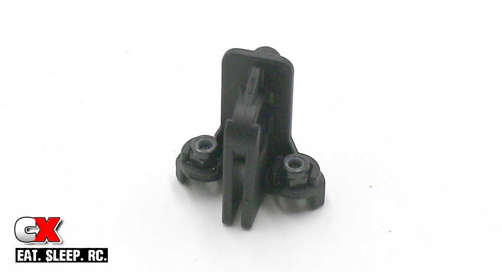
Assemble the additional body mount. You don’t actually use this as a body mount (it’s more for the EB410), but you do need it in place to help keep the wing mount attached.
Manual states to add a drop of CA glue to the locknuts to keep them in place.
Step 8:
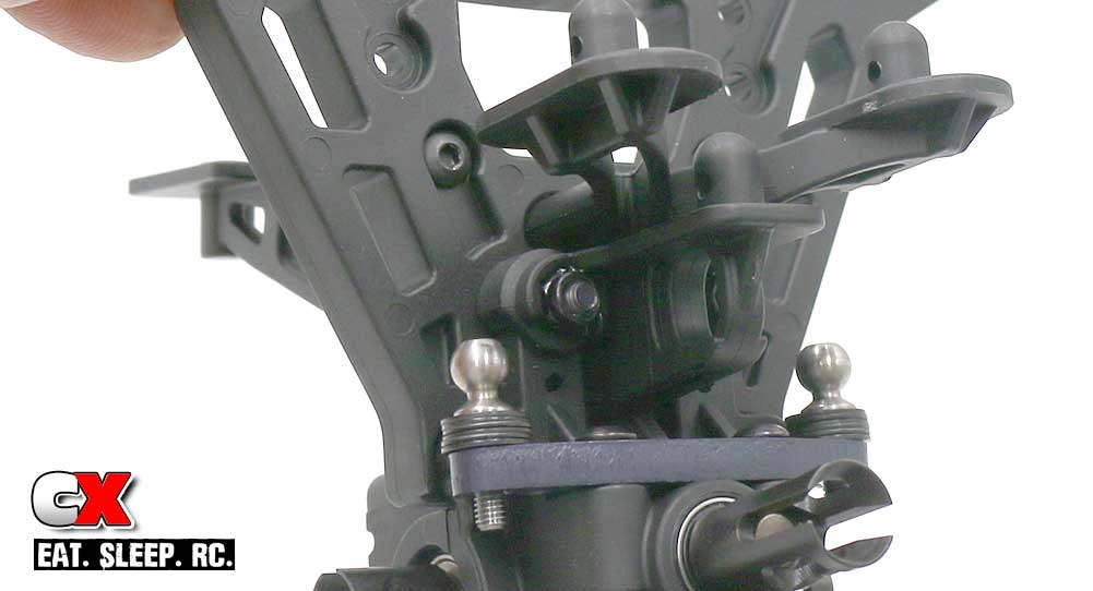
Attach the shock tower assembly to your rear bulkhead.
Step 9:
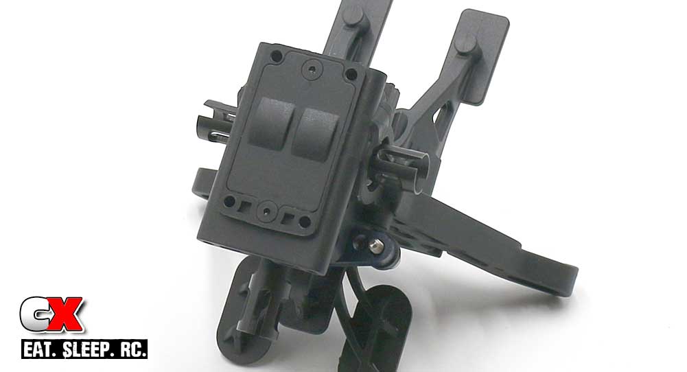
Final step is to cap off the bottom of the bulkhead using the M2.5x6mm screws to keep it in place.
Another simple step. Both bulkheads are done, time to get the suspension mounted up!
Tekno ET410 Online Build – Part 4
The suspension on the Tekno ET410 is about as beefy as you can get on a 1:10 scale truck. Thick a-arms, aluminum arm mounts and a full set of anti-roll bars are all standard features, as is the incredible amount of tuning options to help lock the ET410 in at whichever track you choose to run.
Build Notes:
• In this step, there are two different length setscrews; a 3mm and a 4mm. Make sure, in Step 11, you are using the 3mm setscrew. If you use the 4mm one, your wheels will not fit on the hexes.
• When attaching the turnbuckles, make sure the ‘notch’ is to the left side of the car. If all of the notches are to the left, it makes it easy to understand which way to twist the turnbuckle to make adjustments.
Step 1:
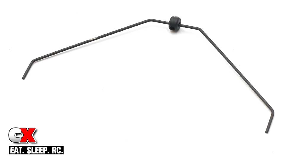
Let’s start this step off with the assembly of the rear anti-roll bar. Slide the plastic piece onto the bar and lock in place with the M3x4mm setscrew. Center it on the bar; you can do a final adjustment in Step 3.
Step 2:
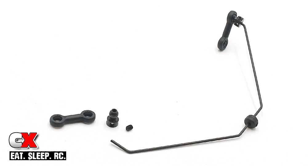
Attach the aluminum anti-roll bar ends on the bar, locking in place with the M3x4mm setscrew. A little dab of blue threadlocker is suggested here. Snap the anti-roll bar links onto the aluminum ends.
Step 3:
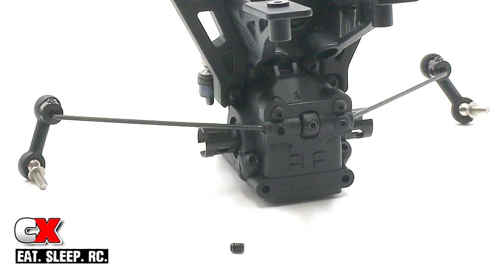
Attach your anti-roll bar assembly to the rear bulkhead (here is where you want to make sure the plastic piece is centered on the bar).
Feed the M3x4mm setscrews into the holes and tighten until they hit the bar, then back them out a 1/8 turn. You want them almost touching the bar but not to the point of hindering its movement.
Take this time to snap the ballstuds into the lower part of the anti-roll bar links as well.
Step 4:
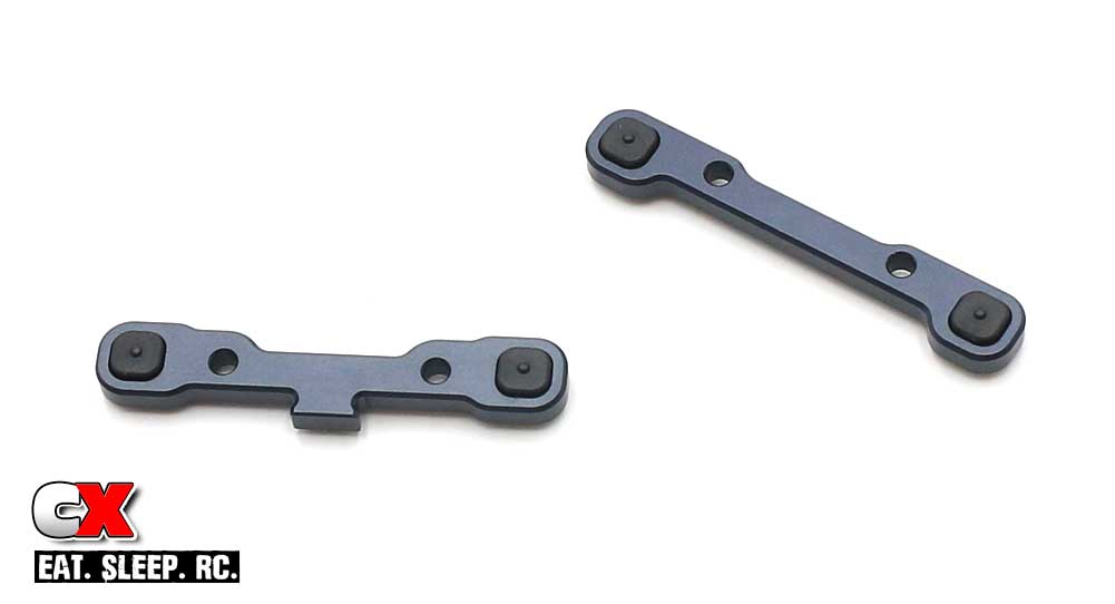
Shown are both of the rear aluminum arm mounts; the one on the left is the ‘C’ block (in front of the rear arms), the one on the right is the ‘D’ block (the one behind the rear arms). Don’t mix them up.
The manual has us starting out with the ‘center dot’ pills, so grab four off the tree and install them as shown.
Step 5:
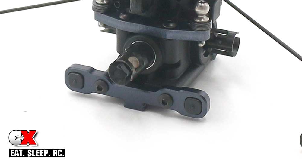
Attach the ‘C’ block to the rear bulkhead.
Step 6:
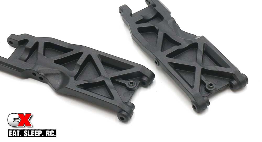
Feed the M4x8mm Droop screws into the rear arms. Don’t worry about them being perfect just yet; you can make final adjustments at the end of the build.
Step 7:
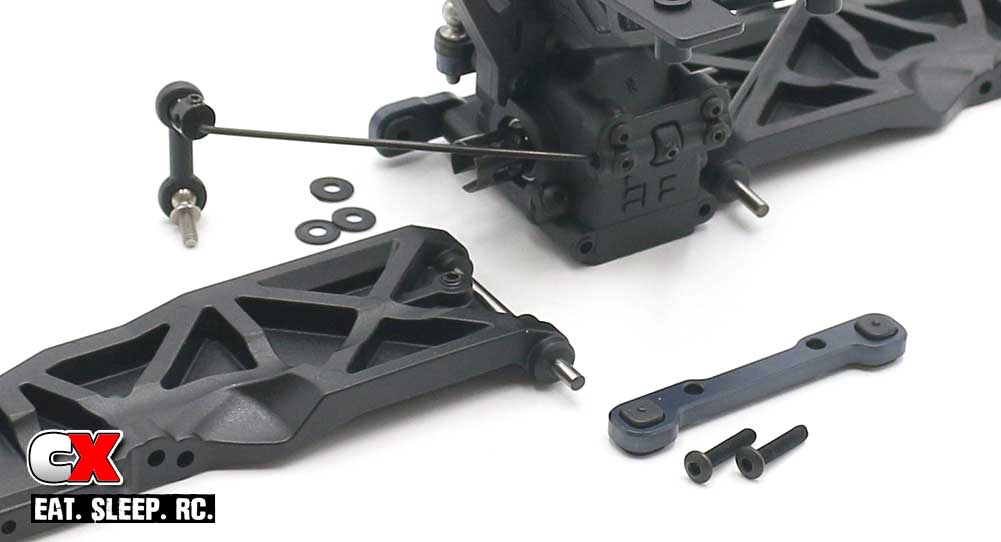
Press the hinge pins into the ‘C’ block. Slide 3 wheelbase shims (2 thin, 1 thick) onto the hinge pin followed by the suspension arm (note the orientation of the arm). Key the ‘D’ block to the hinge pins and press into place, securing it with the M3x14mm screws.
Once tightened, make sure the arms have free up and down movement. If not, give a light tap on the arms to help ‘press’ the pills and spacers into place. You may have to do this in both directions.
Step 8:
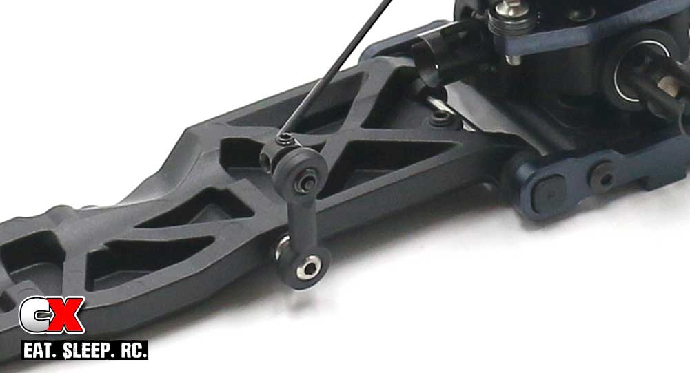
Connect the anti-roll bar ballstud to the arm.
Step 9:
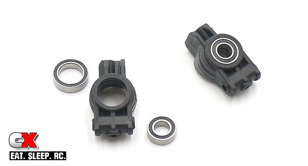
Press the bearings into the rear hubs.
Step 10:
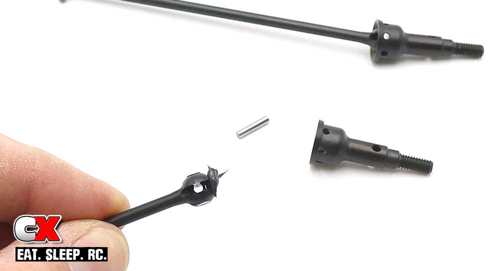
Assemble the axles. Place a small amount of black grease as shown before assembly. This will help keep everything well lubed.
Step 11:
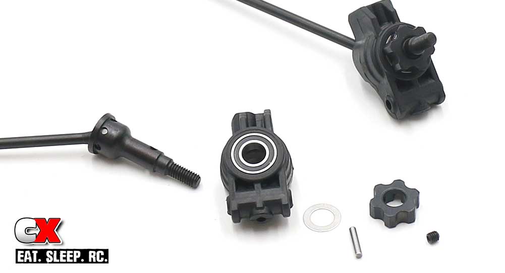
Slide your axle assembly though the hub, add the 6×10 shim and the axle pin. Key the wheel hex to the axle pin, press into place and secure with the M3x3mm setscrew.
Tech Note: Make sure you are using the M3x3mm setscrew for this step.
Step 12:
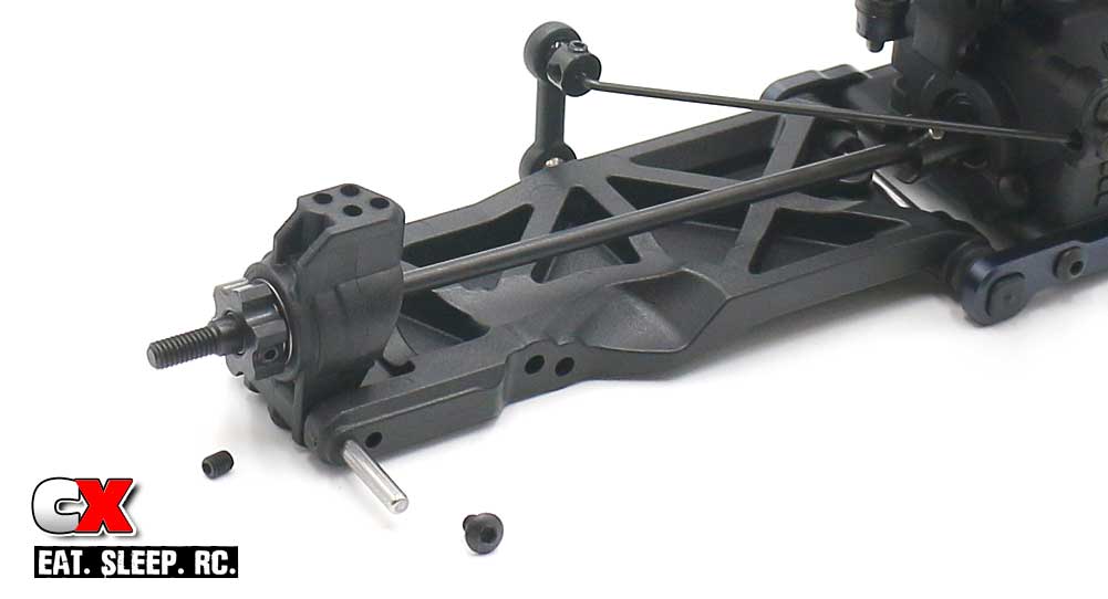
Set the rear hub assembly into place and feed the hinge pin through the arm. Capture it with the M3x4mm screw. You’ll also want to insert the M3x4mm setscrew through the bottom of the hub. Just snug it up – no need to overtighten it.
Step 13:
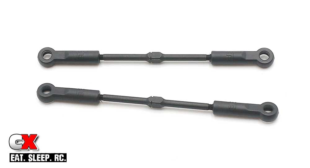
Build your pair of turnbuckles. The suggested lengths are a good starting point.
Step 14:
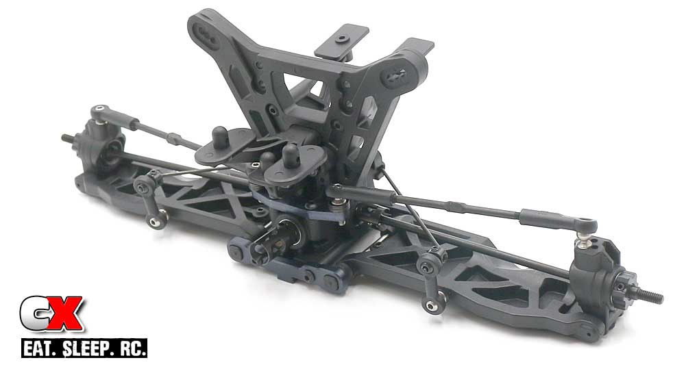
Key the axles to the outdrives on the diff, then pop the turnbuckles into place. Remember, make sure the ‘notch’ in the turnbuckle is to the left side of the ET410.
Excellent work. Clean up your space and let’s move to Part 5, the Front Suspension.
Tekno ET410 Online Build – Part 5
Like the rear, the front suspension on the Tekno ET410 is quite macho. Thick parts, aluminum bits and another anti-roll bar – all standard equipment.
Build Notes:
• In this step, there are two different length setscrews; a 3mm and a 4mm. Make sure, in Step 8, you are using the 3mm setscrew. If you use the 4mm one, your wheels will not fit on the hexes.
• When attaching the turnbuckles, make sure the ‘notch’ is to the left side of the car. If all of the notches are to the left, it makes it easy to understand which way to twist the turnbuckle to make adjustments.
• The additional setscrew in Step 11 is there to make sure that hole does not deform while using the inside hole. Should you move the ballend to the outside hole, make sure you insert the M3x4mm setscrew into the unused hole.
Step 1:
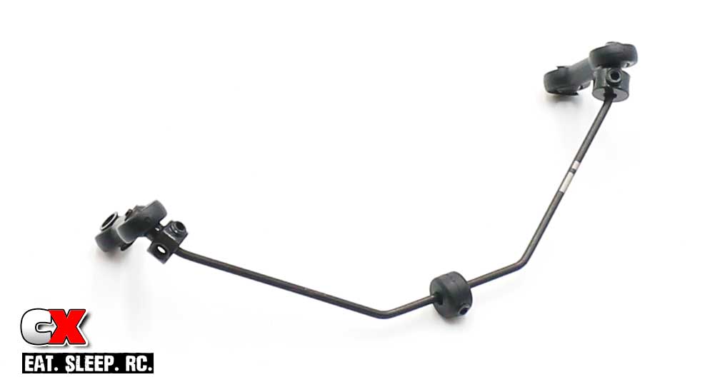
Assembly of the front anti-roll bar is just like the rear; only difference is you’ll be pressing balls into the bottom hole of the plastic links instead of ballstuds. You can use that for reference if you need a step-by-step here.
Step 2:
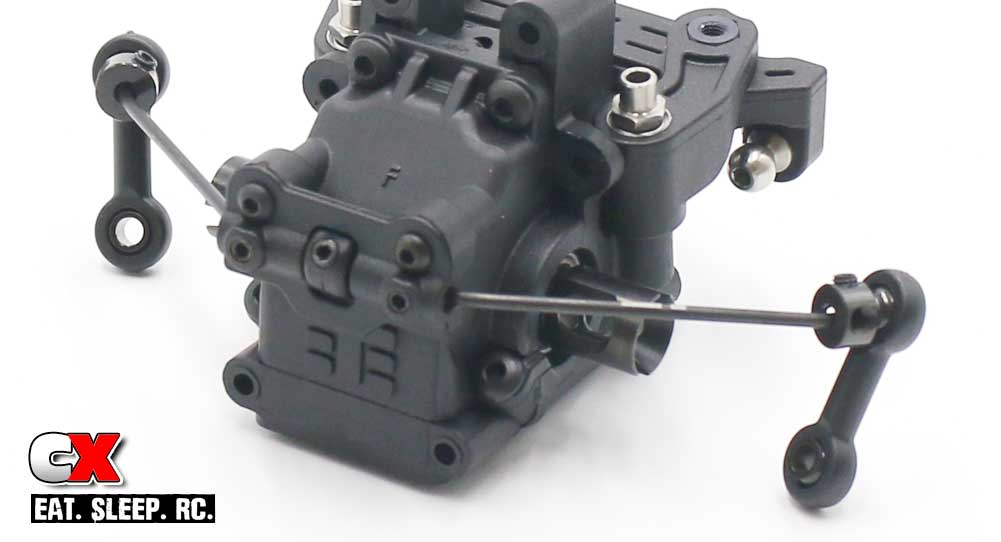
Attaching it to the bulkhead, same as the rear.
Step 3:
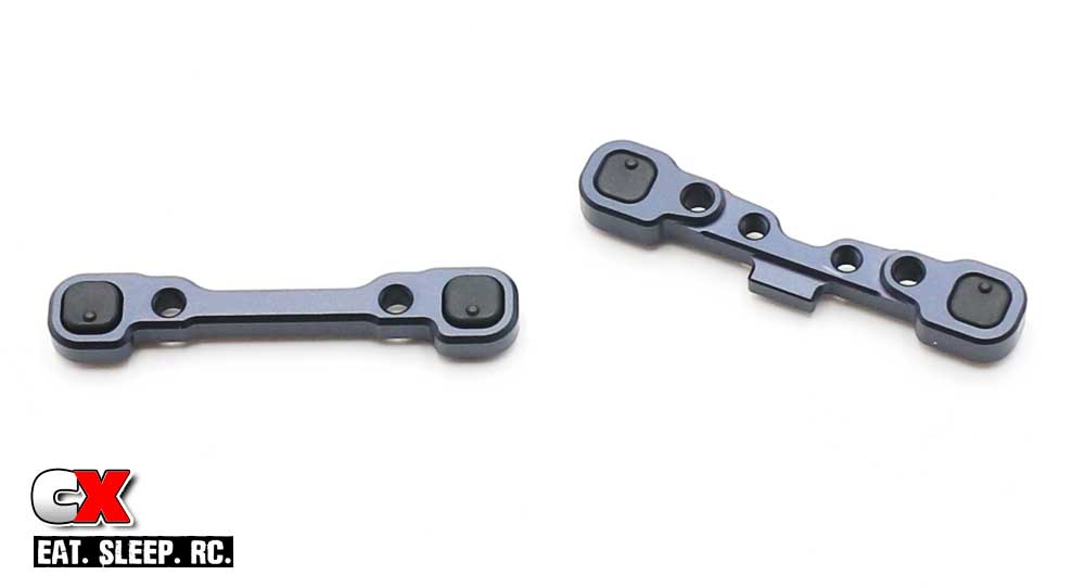
Two aluminum arm mounts; the one on the left is the ‘B’ block, the one on the right is the ‘A’ block. Low-dot pill in the ‘B’ block, high-dot pill in the ‘A’ block.
Step 4:
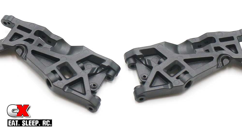
Insert the Droop screws into the arms. Again, we’ll ‘set’ them at the end of the build.
Step 5:
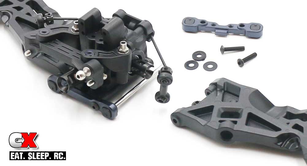
Attach the ‘B’ arm mount to the bulkhead, press the hinge pin in place followed by the suspension arm (note the orientation), 3 shims (2 thin, 1 thick) and then the ‘A’ arm mount.
Step 6:
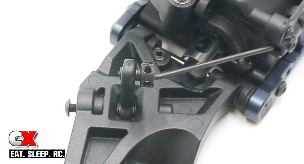
Slide the anti-roll bar link into the gap in the arm and secure with the M3x20mm screw.
Step 7:
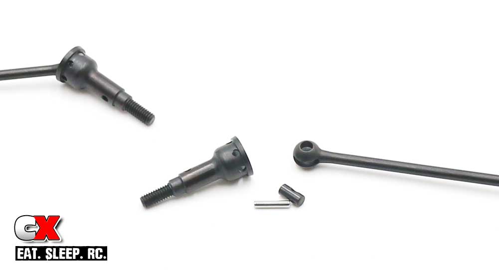
Assemble the rear axles.
Step 8:
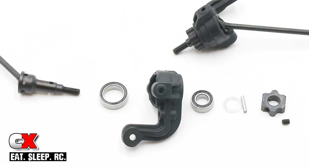
Press the bearings into the steering blocks. Slide the axles through the blocks followed by the shim and axle pin. Key the wheel hex to the axle pin and lock in place with the M3x3mm setscrew.
Step 9:
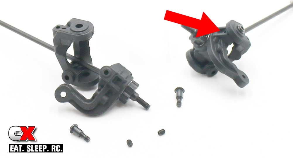
Key the steering blocks to the caster blocks and screw the steering block screws into place. Do not overtighten – a snug fit will do. Using the M3x4mm set screws (make sure they are the 4mm ones), feed them into the holes (one marked with the red arrow) and tighten until there is a snug fit. Do not overtighten these either.
Step 10:
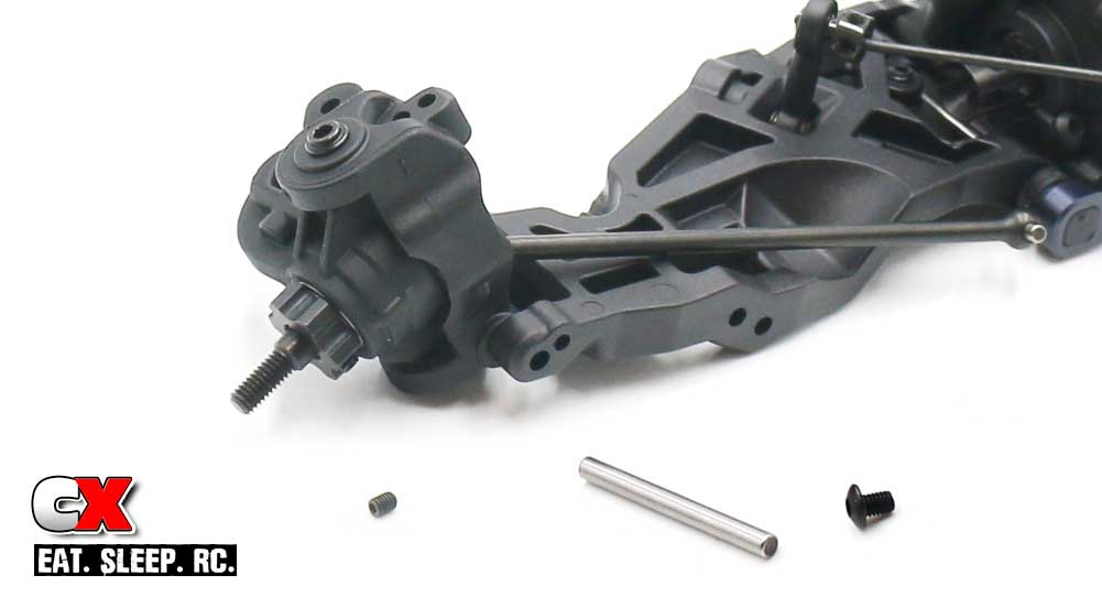
Set the steering assembly into place as shown and insert the hinge pin. Lock the hinge pin in place with the M3x4mm screw. You will also need to insert another M3x4mm setscrew into the bottom of the steering block to help capture the hinge pin; a snug fit here is all that’s needed.
Step 11:
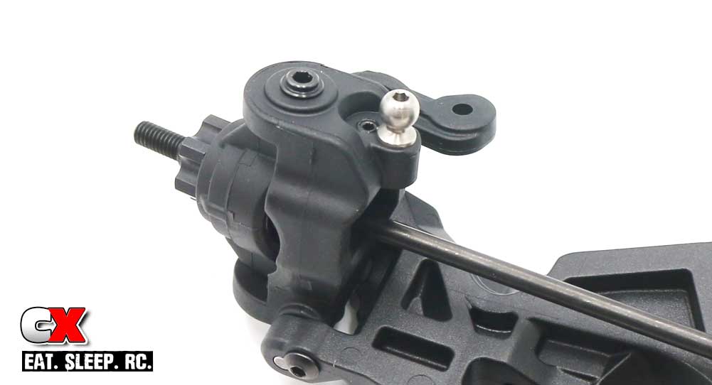
Insert the 8mm ballend and M3x4mm setscrew into the top of the caster block.
Step 12:
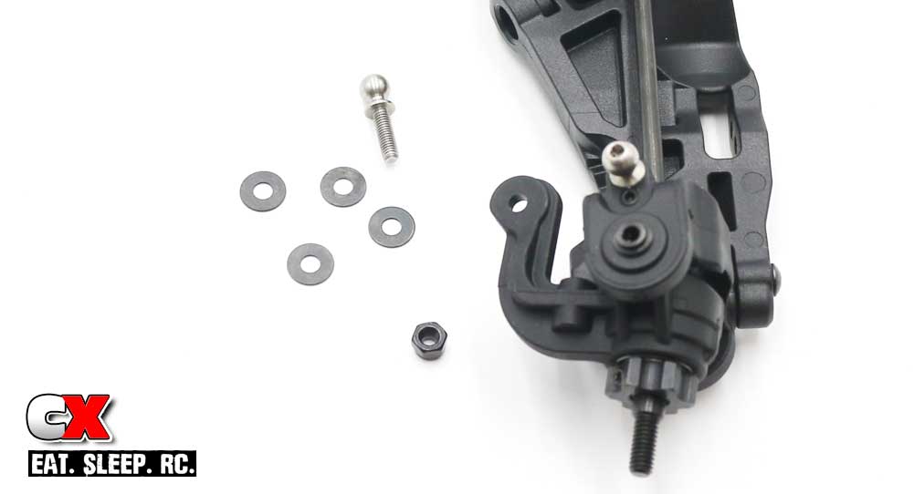
Press the locknut into the bottom of the steering arm and feed the 10mm ball end into place. Make sure to include four of the shims.
Step 13:
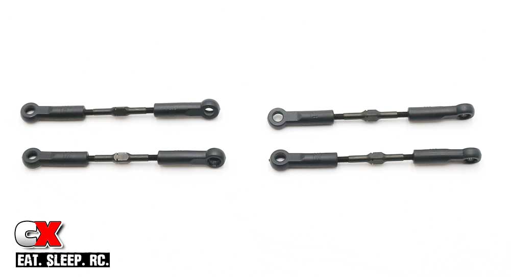
Build more turnbuckles. The manual lenghts are a good starting point.
Step 14:
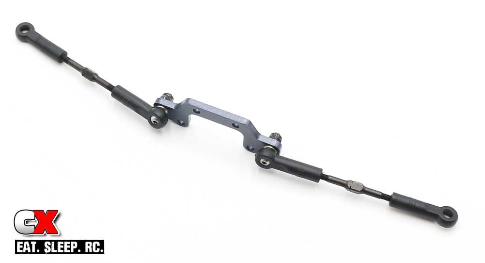
Assemble the camber link brace (use the upper holes). Pop the steering turnbuckles on from Step 13. Make sure the ‘notches’ are pointing to the left side of the car.
Step 15:
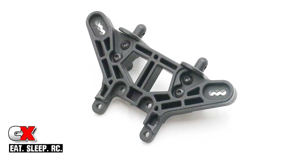
Attach the body posts to the shock tower. Note the orientation of the tower.
Step 16:
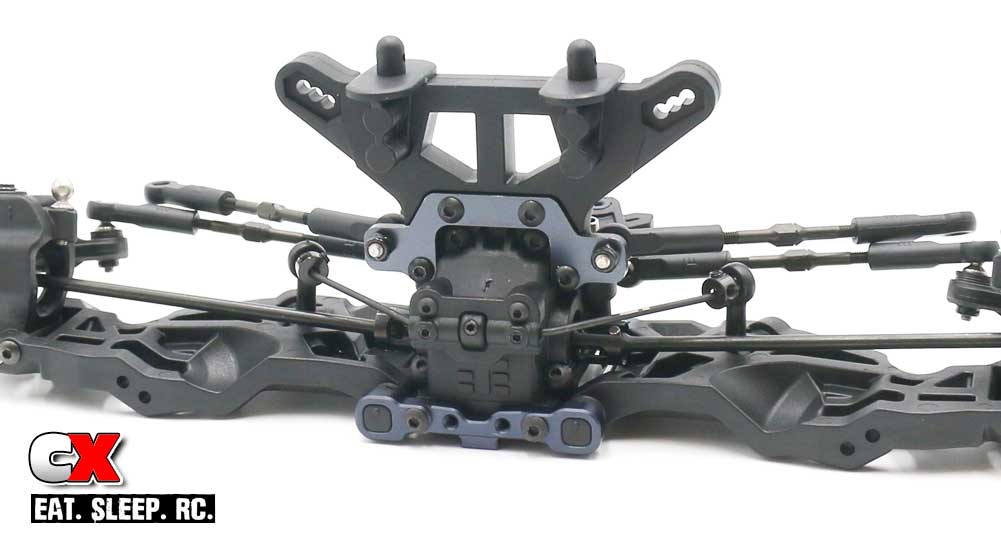
Pop the steering links from Step 13 into place. Using the camber link plate, sandwich the shock tower to the front bulkhead.
Step 17:
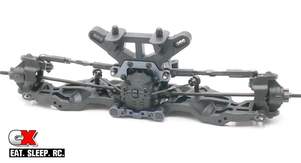
Pop the remaining camber link ends on to the open caster block ballstuds. This is a good time to double check that your ‘notches’ are all facing the left side of the car.
Ok – done with the major build parts. Time to start attaching it all to the chassis!
Tekno ET410 Online Build – Part 6
Now that we have the front and rear clips of our Tekno ET410 built, let’s start getting all the bits attached to the chassis.
Speaking of the chassis, Tekno has provided the ET410 with a 3mm, 7075 CNC-machined plate with all kinds of pockets cut into it for weight savings. Beautiful piece for sure!
Build Notes:
• None
Step 1:
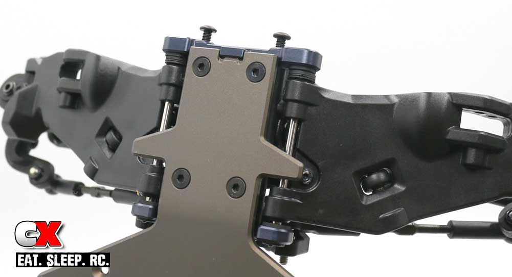
Attach the front clip to the front of the chassis. Now, while this may seem easy, there are a few additional steps that have to be taken.
First, you’ll need to loosen up the ‘A’ mount screws quite a bit, then pull the ‘A’ mount off the hinge pins slightly. Set the front clip onto the chassis and carefully press the ‘A’ mount back in place. Note that the bottom of the ‘A’ mount has a little latch that catches a lip on the chassis; just make sure that the latch is UNDER the lip (see photo).
Once set in place, secure the bulkhead to the chassis. Note the two different screw lengths; 8mm ones up front, 10mm ones near the back.
Step 2:
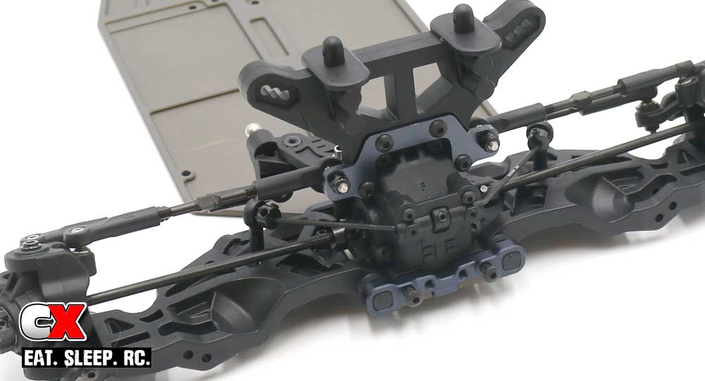
Front clip attached, ready to tighten up the ‘A’ mount screws.
Step 3:
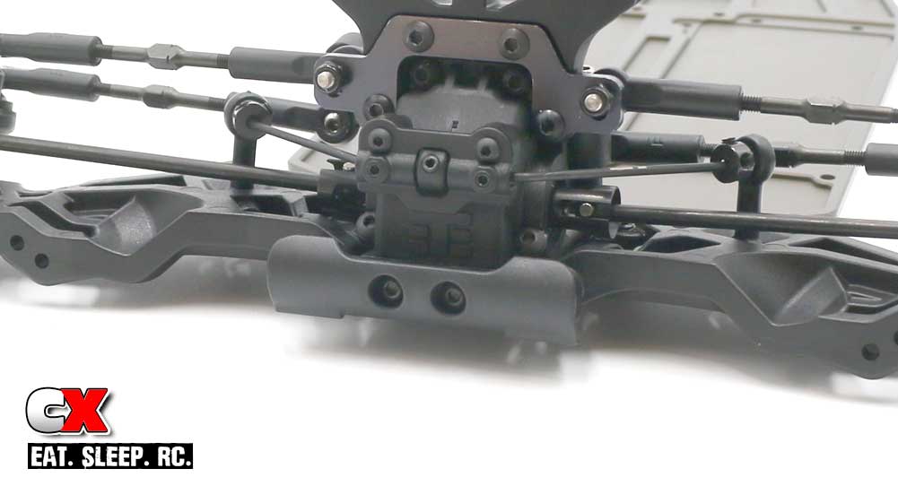
Attach the front bumper.
Step 4:
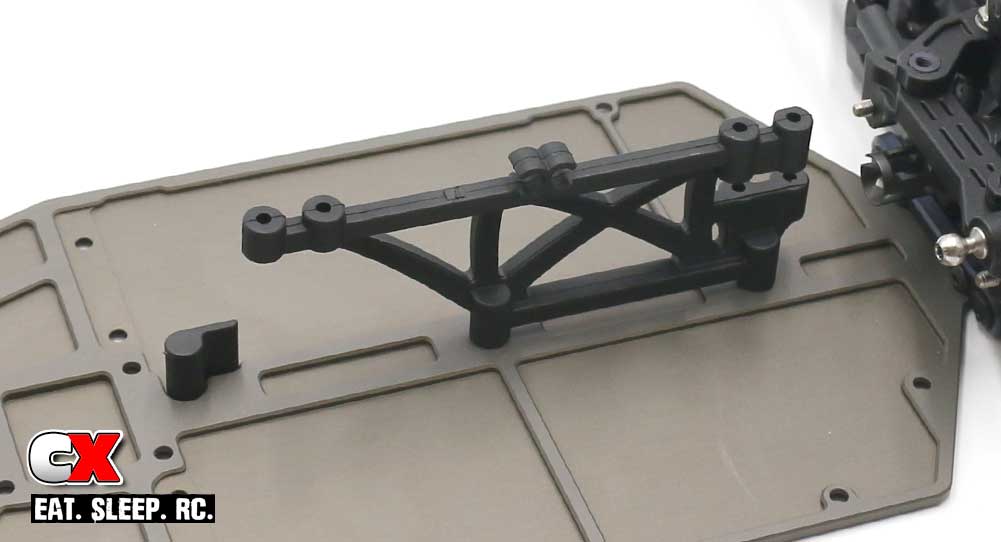
Attach the center brace and battery stop.
Step 5:
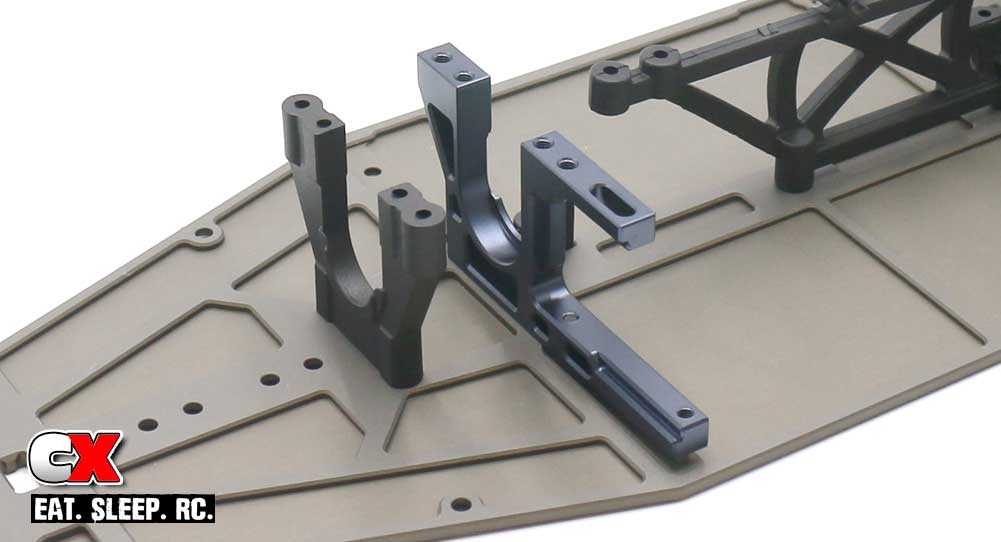
Attach the center bulkhead halves. Note orientation. Blue threadlocker is suggested for the aluminum bulkhead.
Step 6:
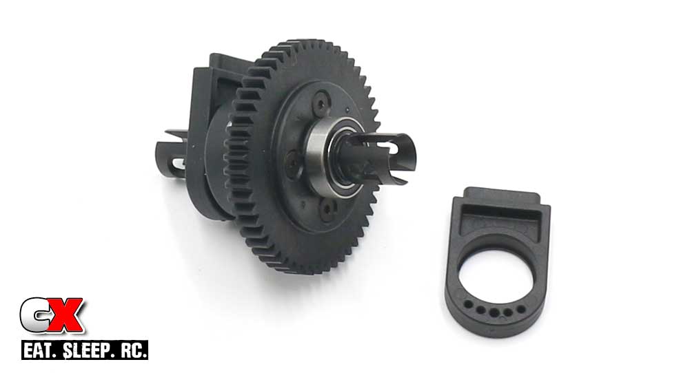
Press the 10×15 bearings into the center diff support, then press onto the center diff. Note the orientation of the supports.
Step 7:
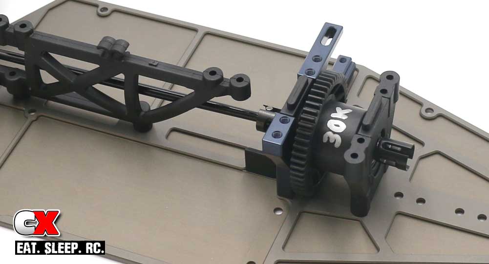
Key the front driveshaft into the front diff output, into the center diff and slide the center diff assembly into the bulkheads. You may need to loosen up the screws to the center chassis brace to make this fit.
Note the orientation of the center diff.
Step 8:
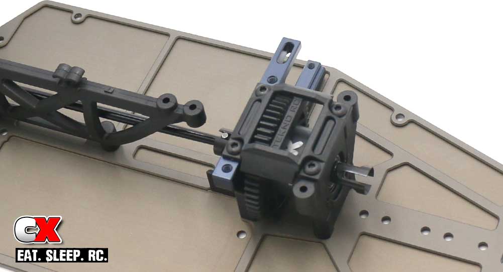
Cap the center diff. Blue threadlocker is suggested on the screws going into the aluminum bulkhead.
Step 9:
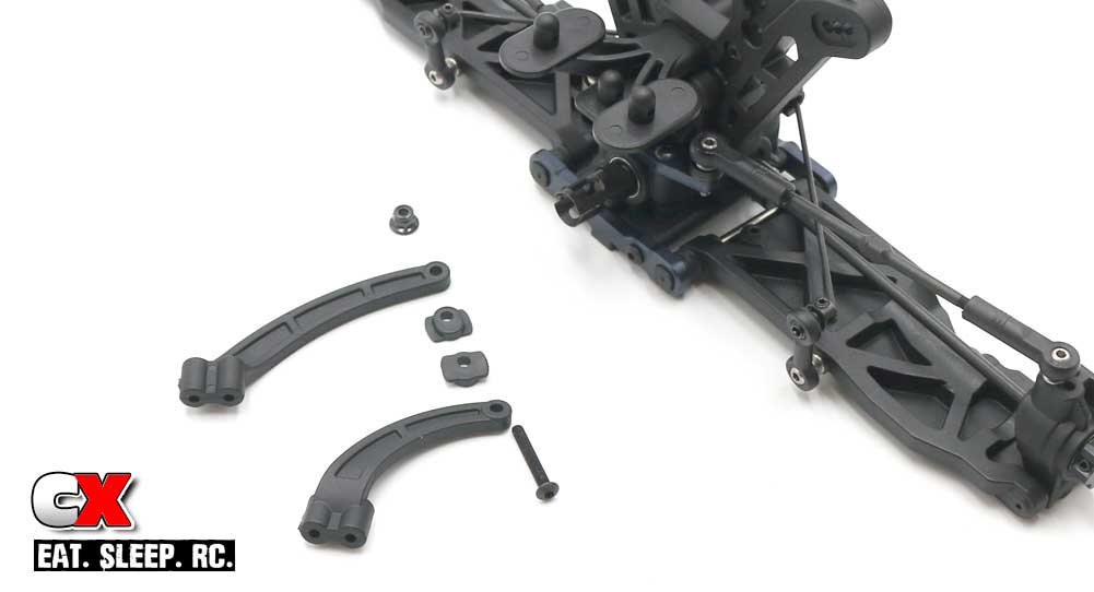
Attach the rear chassis brace. Note the direction of the inserts; hole up.
Step 10:
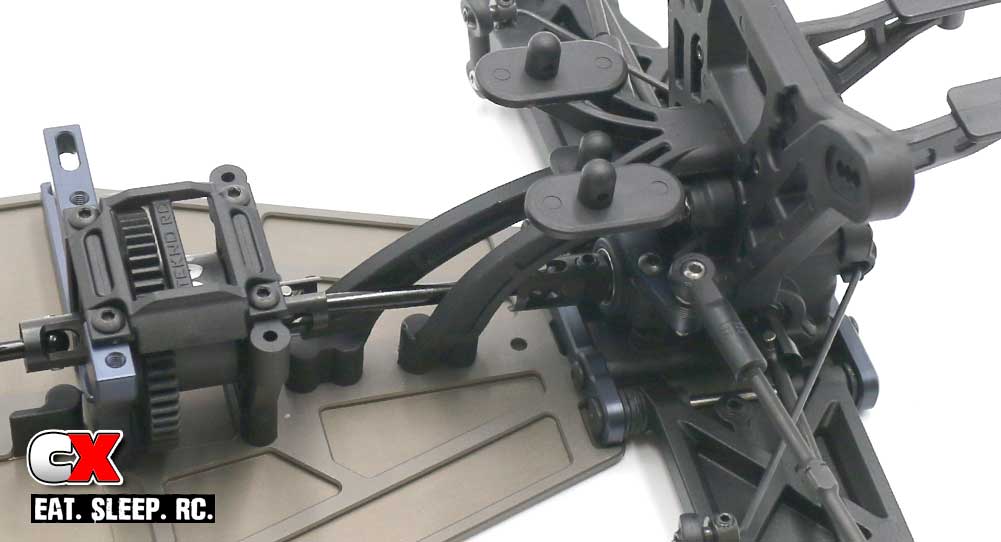
Attach the rear clip assembly to the chassis. Don’t forget to include the rear driveshaft.
Very nice – starting to look like the ET410 now, right? Clean off some space and get some clean towels ready – it’s shock time!
Tekno ET410 Online Build – Part 7
The Tekno ET410 comes with some pretty massive shocks – 13mm hard-anodized threaded shocks to be exact. In addition to their beefy design, they include 3.5mm shafts, dual glide x-ring cartridges and locking spring perches.
Build Notes:
• Shock fluid. It’s a messing substance if you spill it. Have a clean, covered work space with some towels or rags for clean up.
• You might also want to get your hands on a shock stand, great for setting the open shocks aside while the air bubbles rise from the fluid. Something like this one from ProTek is perfect for this task.
Step 1:
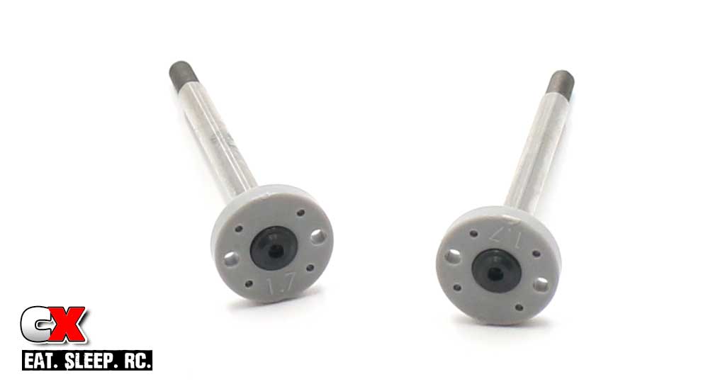
Assemble a pair of shock shafts; a light drop of blue threadlocker is suggested here.
Step 2:
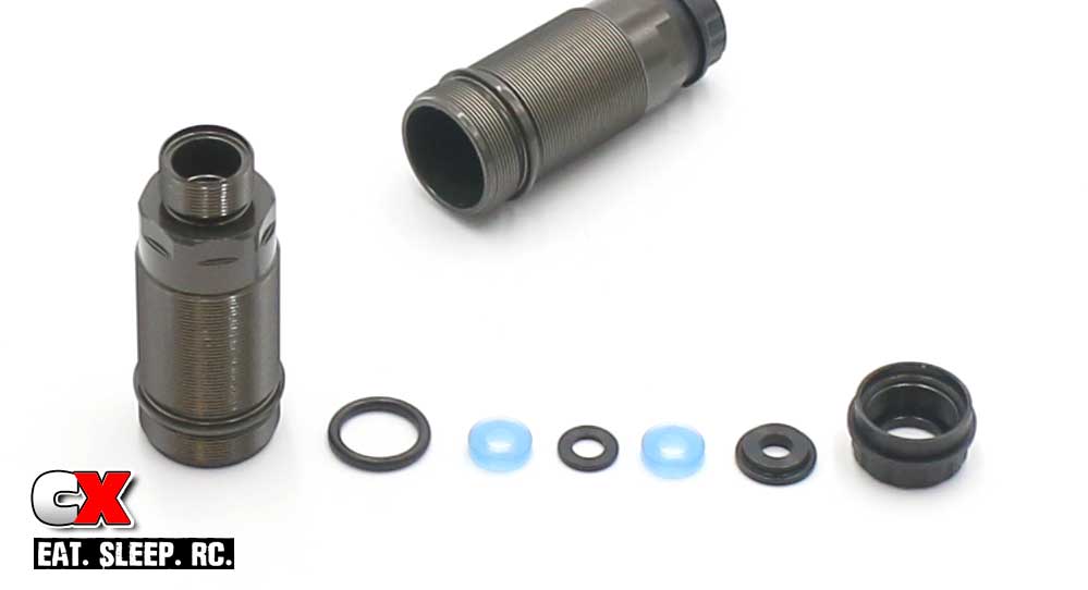
Build the bottom shock cartridge; black o-ring (over the bottom of the shock), blue o-ring (inside) followed by a black spacer, another blue o-ring and bottom plastic cap. Screw on the lower cartridge cap.
Step 3:
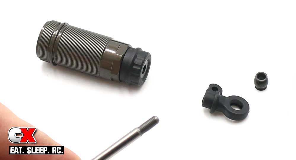
Squeeze a healthy drop of shock oil onto the threads of the shock shaft and slide into the shock. Press slowly so you don’t rip the o-rings. Pop a ball into the shock bottom and screw that assembly onto the shock shaft. Screw on until the threads don’t show.
Step 4:
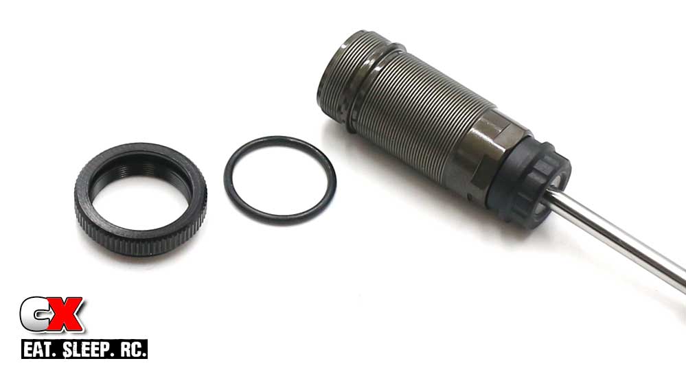
Fit the larger o-ring into the collar and thread onto the shock.
Step 5:
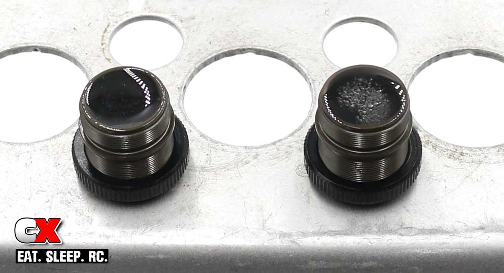
Fill to the top with the #550 oil. Slowly work the shock shaft up and down a few times to release any air from the bottom of the shock, then place in a shock stand for a few minutes. You can see from the picture that the left shock is free of air, the right still has air bubble rising.
Step 6:
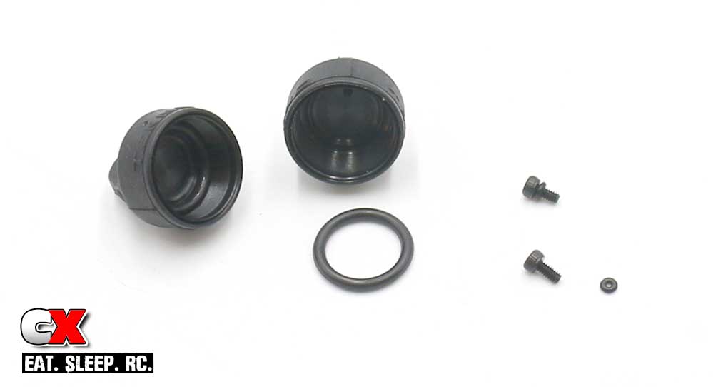
While you’re waiting for the oil to rise, we can prep the other parts. Fit the medium o-ring down into the shock cap. Next, fit the teeny tiny o-ring over the M2x4mm screw. Patience is key here – this little bugger is a bit of a pain. I suggest washing your hands with soap and water prior to trying this. Any oils or fluids on your fingers will make this almost impossible.
Step 7:
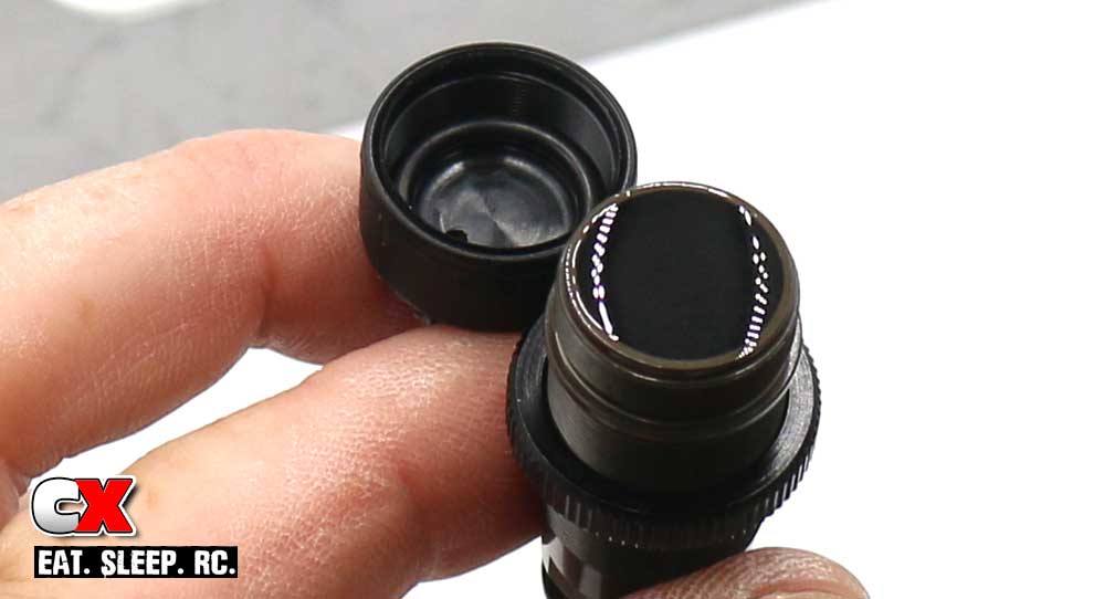
Once all the bubbles have left the shocks, refill to the top. A light ‘crown’ is a good place to start the oil at.
Step 8:
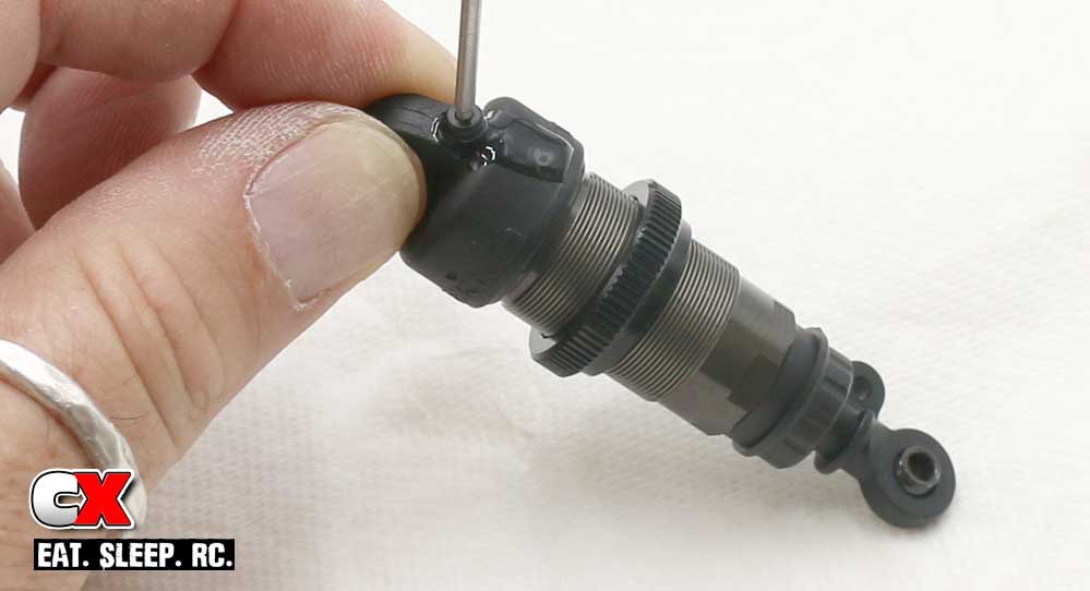
Thread the shock cap on, tilting the shock to the side to keep the fluid from rushing out the hole. Now fully compress the shock – you’ll see fluid seep out the hole. Cap off the hole with the o-ring equipped M2x4mm screw. Clean off any of the excess shock fluid.
Step 9:
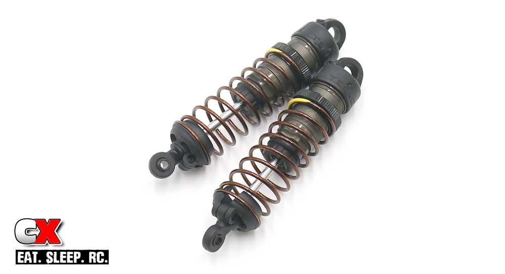
Insert the spring and spring perch. Use the M3x8mm setscrew through the spring perch to keep it secure on the shock.
Step 10:
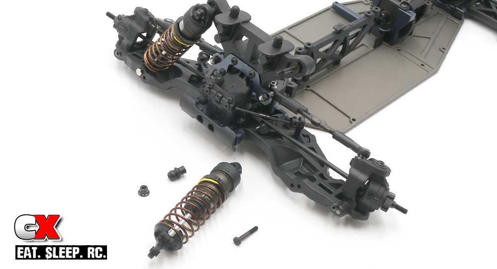
Attach the shocks to the front of the ET410; middle hole in the tower, outside hole on the arm.
You’ll also notice a silver and black lower shock screw; the silver is an opposite thread, meaning you have to turn it to the left to tighten it (when installed on the right side of the car). The black screw is normal thread, meaning you have to turn it to the right to tighen it (when installed on the left side of the car).
Step 11:
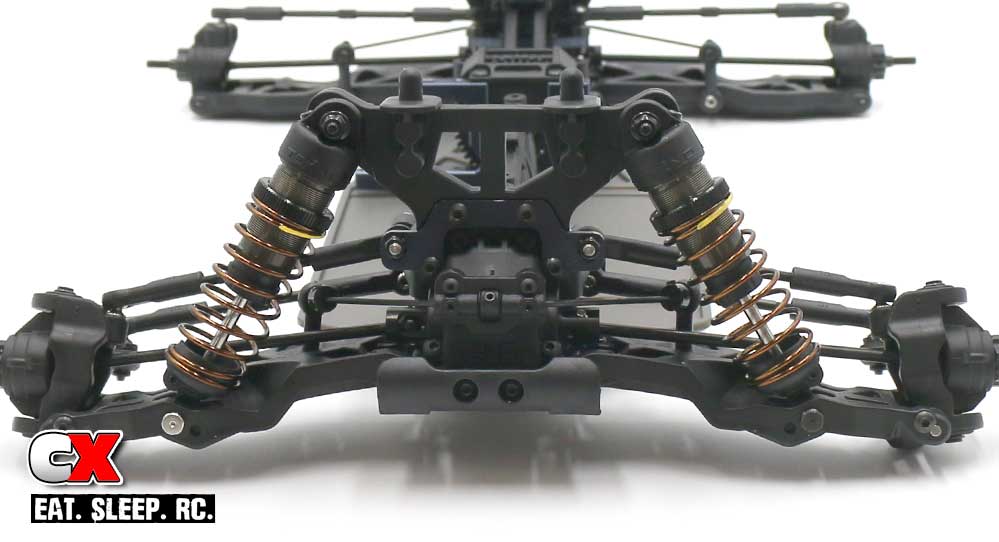
Your completed front shocks.
Step 12:
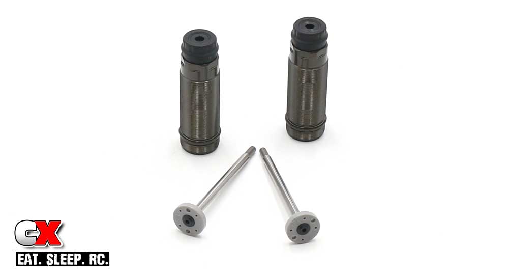
The rear shock build is exactly the same as the front. Build the shafts, install the o-ring, build the cartridges. Oil on the threads, slip it through and install the shock ends.
Step 13:
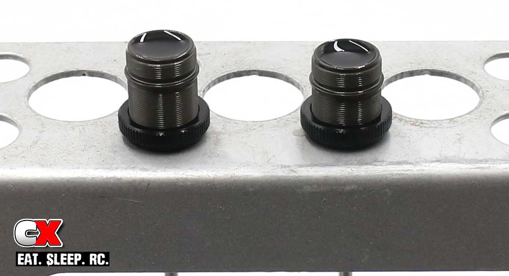
O-ring in the collar, thread the collar on and fill with #350 oil. Plunge the shaft up and down a few times to release any oil, then set aside.
Step 14:
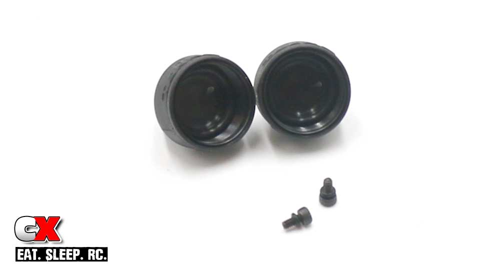
Build the caps and bleeder screws.
Step 15:
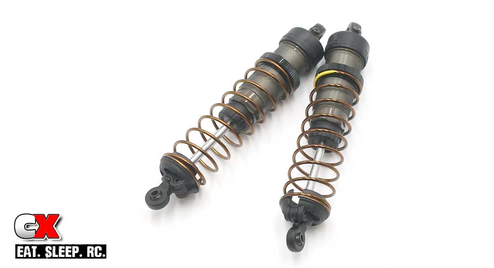
Refill the shocks, install the caps, compress and cap the bleeder hole. Wipe off any excess oil, install the springs, perches and M3x8mm setscrew.
Step 16:
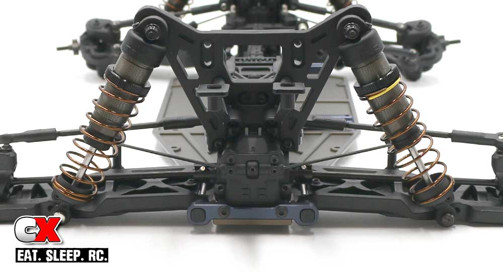
Attach the shocks to the ET410; silver screw on the left, black screw on the right.
Boom – DONE! At the end of the build you can set the ride height and such, but for now, clean up any excess oils and lets get to the next step – the electronics!
Tekno ET410 Online Build – Part 8
Tekno’s ET410 will accept almost all 1:10 scale electronics, with some guys already installing 1:8 scale systems. I went with the same gear I used in my EB410 – simply because it worked, it’s fast and it fits!
We have the following installed:
• #FUTK4908 Futaba 7PX 7-Channel Transmitter
• R1 Wurks Digital Low-Profile Drive Servo, 80mm Wire
• R1 Wurks 6000mAh 2S LiHV Graphene Shorty LiPo Battery
• R1 Wurks Digital-2 200A Brushless ESC
• R1 Wurks 10.5T V15 Brushless Motor
Build Notes:
• The manual shows the battery posts to the rear of the car; this is fine and dandy, but you won’t be able to plug (or unplug) your battery without completely removing the pack. Option 2 is to flip the battery and shorten the wires.
Step 1:
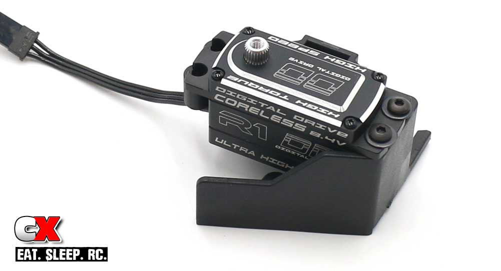
Let’s start off by installing the servo. Attach it to the mount as shown. Note the orientation of the output shaft on the servo.
Step 2:
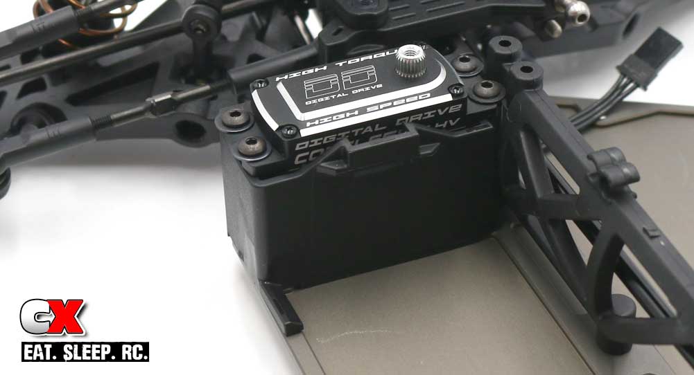
Attach the servo assembly to the chassis. You’ll also want to make sure that the servo lead feeds to the opposite side of the car.
Step 3:
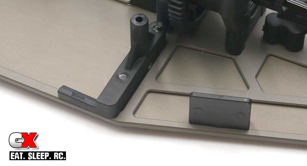
Install hte battery tray/battery strap mount. If you’re going to be using Velcro, install the Velcro body mount.
Step 4:
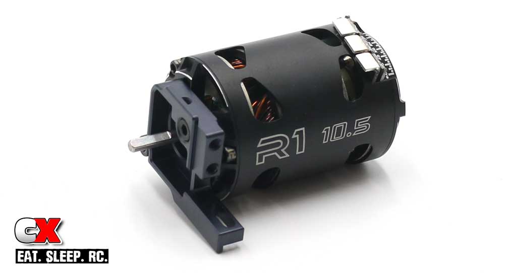
Attach the motor to the aluminum motor mount. Blue threadlocker is suggested here.
Step 5:
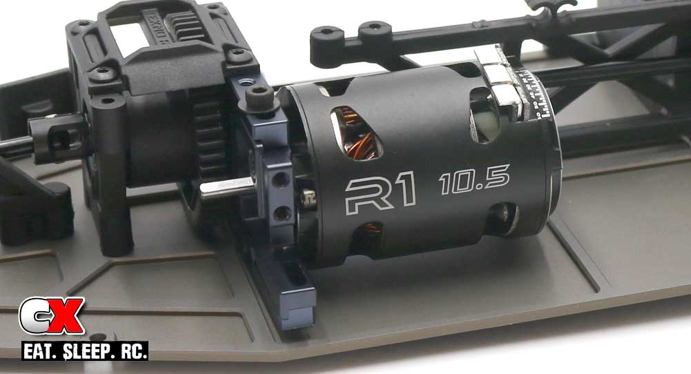
Slide the motor mount into the center aluminum bulkhead and secure with the M3x10mm screws (and washers). Blue threadlocker is suggested here. Note the orientation of the motor tabs. You’ll want to make sure they are easily accessible.
Step 6:
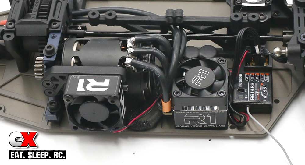
From here on out, the electronics install is up to you. I’ve installed mine like this so you can get an idea of where they go; your install might vary. I’ve also attached a fan and fan mount to the motor mount.
I would also test fit the splash guard from Step 7 to make sure your electronics install doesn’t interfere with it.
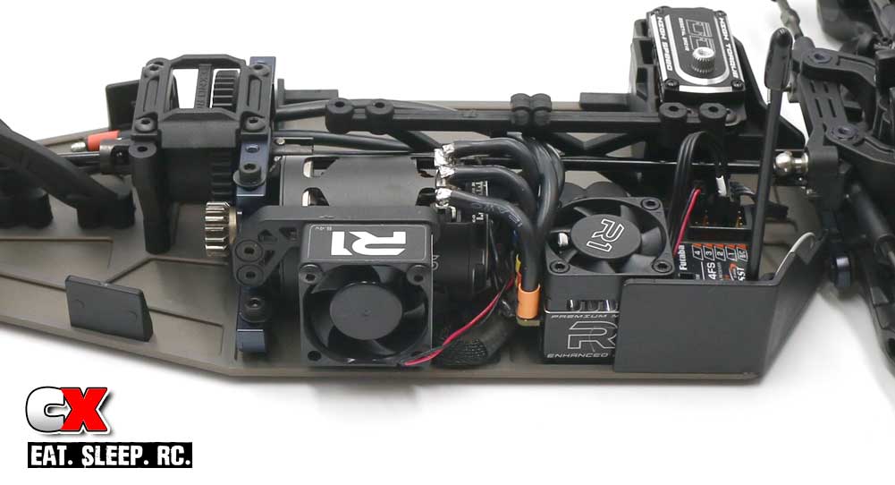
Step 7:
Once you get your electronics installed, attach the front splash guard and rear Velcro body mount. Don’t forget your antenna tube and cap in this step as well.
Step 8:
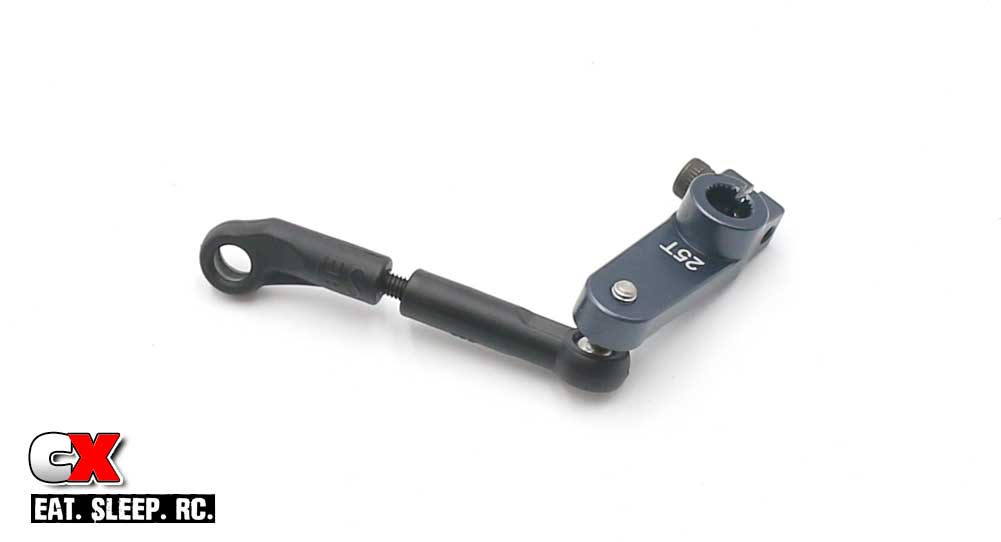
Build the servo horn and drag link. The kit comes with a plastic servo horn but, from past experience, upgrading to Tekno’s Aluminum 25T Servo Horn is must.
Step 9:
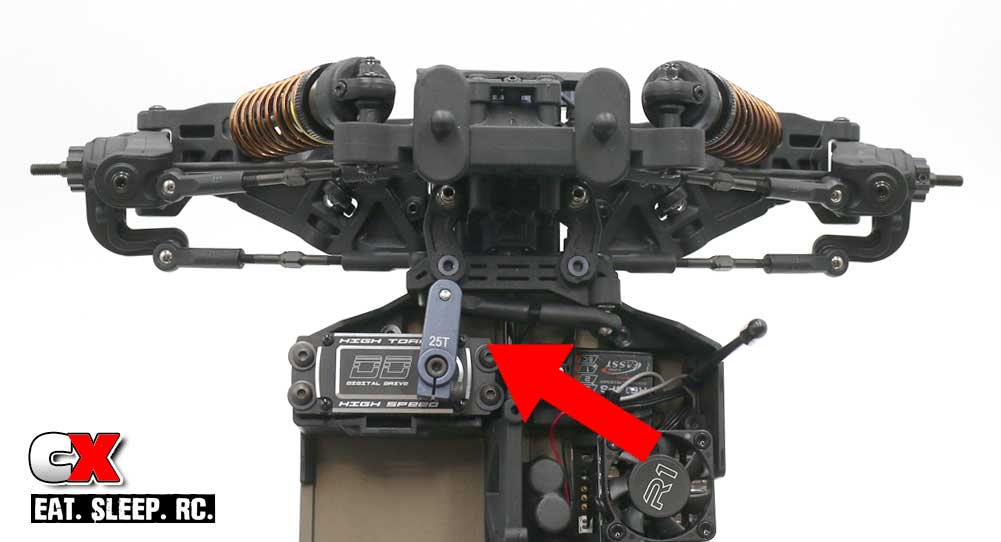
Attach the servo horn assembly to your ET410. Note the red arrow; this calls out Tekno’s ‘4° from 90’ horn placement.
Step 10:
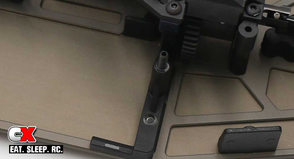
Add the M3x18mm setscrew.
Step 11:
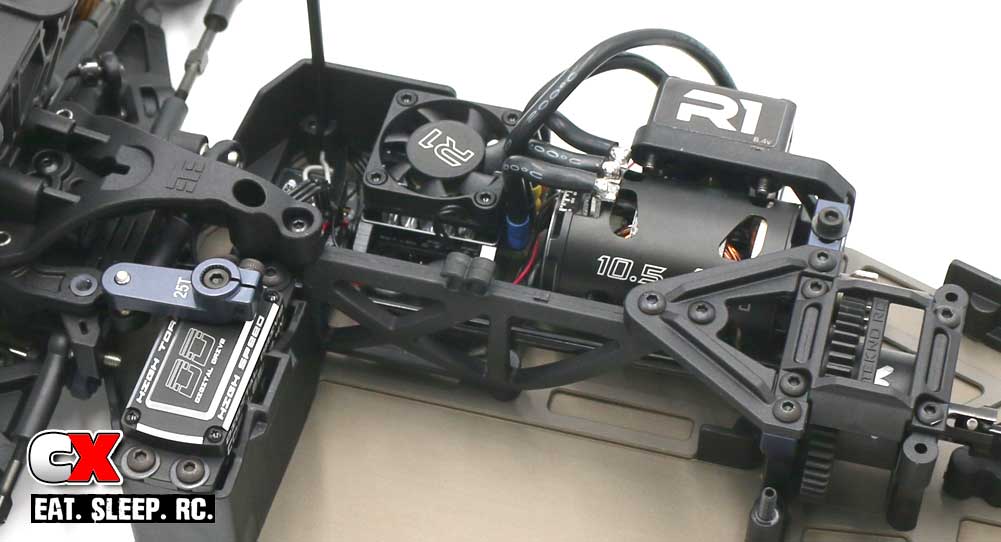
Attach the front and rear braces that support the center chassis brace.
Step 12:
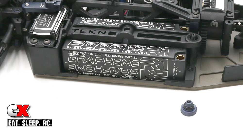
Slip the black o-ring over the bottom part of the thumbscrew. Drop your battery into place and secure with the battery strap and thumbscrew.
Step 13:
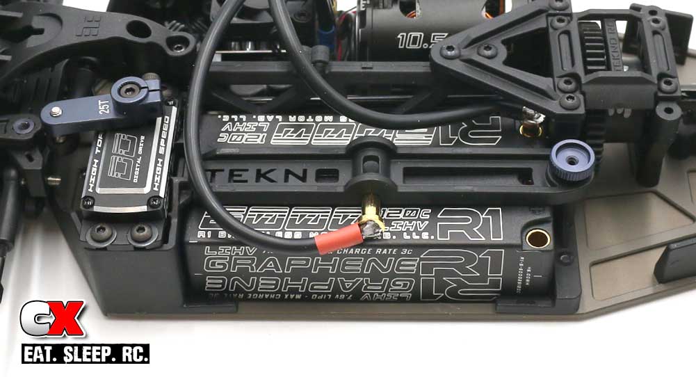
Plug in your pack and you’re ready to rock and roll!
At this time, you might want to fire up the ET410 to make sure everything is working as it should. Would hate for you to get to the track and something has been installed incorrectly…
Ok, on to the final assembly steps…
Tekno ET410 Online Build – Part 9
The final steps in the Tekno ET410 are the wheels and tires, Velcro install and body.
For the wheels and tires, I’m using:
• #8262-03 Pro-Line Racing Positron T 2.2″, MC Compound
• #7852 Team Associated Truck Hex Wheels, White
Amazing paintwork by the one and only Sharkbait Designworks! This dood is simply amazing!
Build Notes:
• Tekno has included three wing shims with the ET410; a 0° (flat), 1.5° and 3°. You can place in different configurations to adjust the rear downforce of the ET410.
Step 1:
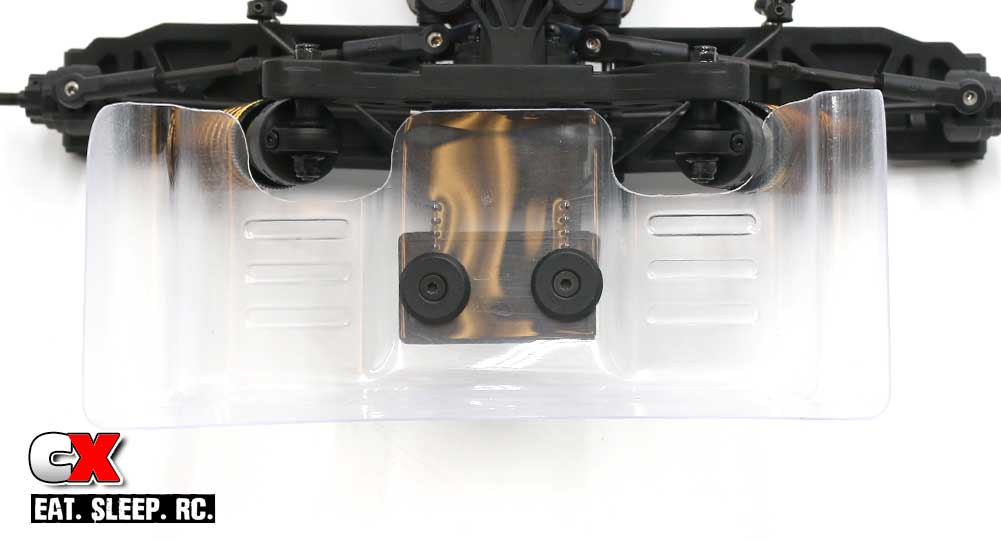
Attach the wing to the rear of the ET410. The kit wing shim calls for the 0°, so that’s what we’ll start with.
Step 2:
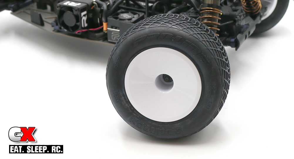
Slip on your wheel and tire combo of choice and secure with the serrated wheel nuts.
Step 3:
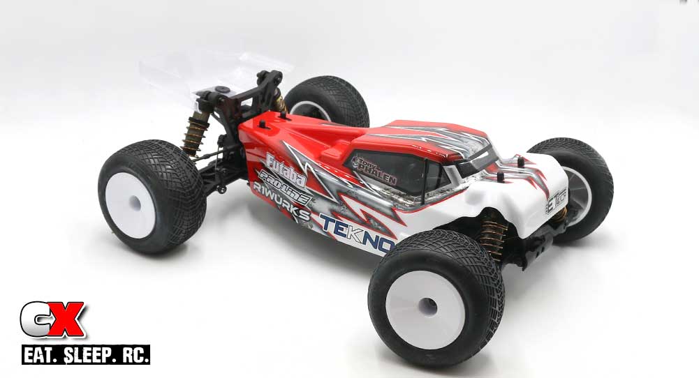
If you’re using the included Velcro, go ahead and install that now. Use the matching piece on the body. I’ll be using both the Velcro and body clips. I plan on airing this truggy out and want to minimize any air under the body!
So there ya go – a full, step-by-step build of the ET410. What an amazing vehicle – time to get it out on the track and have some fun!
Thanks for following along!

