
Tekno EB410 Buggy Online Build
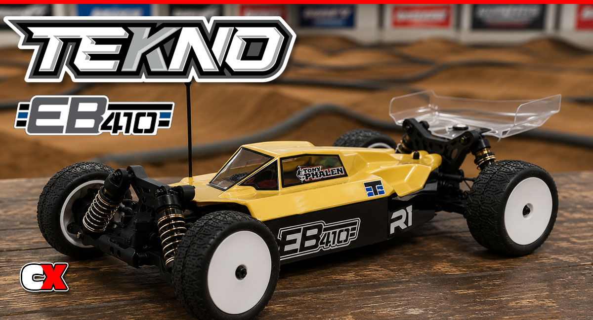
Tekno RC pretty much shocked the world when they released info about a 1:10 scale buggy coming to market. They’ve had some great success in the 1:8 scale scene, so it only seems fitting that a smaller car could do some damage to the other manufacturers.
Looking at this ride, I’ve come to the conclusion that Tekno took hints from their 1:8 scale program and shrunk them down to 1:10 scale – the parts are beefy, drivetrain is bulletproof and the handling is exceptional. One of the best parts is that even though the EB410 looks like a tank, it’s actually one of the lightest buggies on the market!
Tekno RC EB410 Buggy Build – Part 1
Tekno’s EB410 comes equipped with 3 high-quality fluid-filled gear differentials. The front and rear use steel gears while the center (spur gear) comes with a strong molded plastic gear.
Build Notes:
• Building diffs can be a bit messy, so make sure you are working on a protected surface with plenty of rags or towels for clean up.
Step 1:

Before we start building, let’s take a quick look at the fluids Tekno has included with the EB410. There’s a small tube of both black grease and blue threadlocking compound as well as 15K fluid (for the front and center diffs), 7K fluid (for the rear diff) and 500wt shock fluid. There’s enough here for the build and a couple rebuilds.
Step 2:
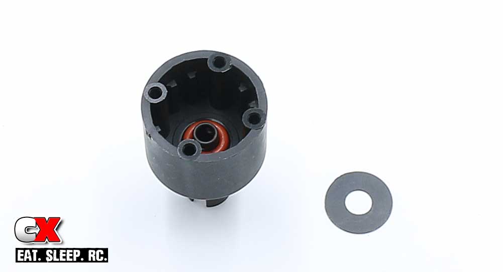
Ok, let’s start by building the center diff. The first step is to apply a liberal amount of black grease to the groove in the outdrive and slide it into the diff housing. Follow that up with a red o-ring and 14mm diff shim.
Step 3:
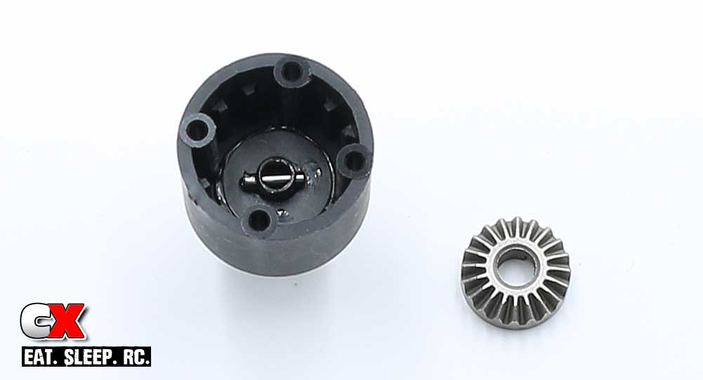
Press the 14mm shim down to seat the o-ring, then slide the chrome pin through the hole in the outdrive. Apply a small amount of black grease to the back of the sun gear and drop it into place, keying it to the chrome pin.
Step 4:
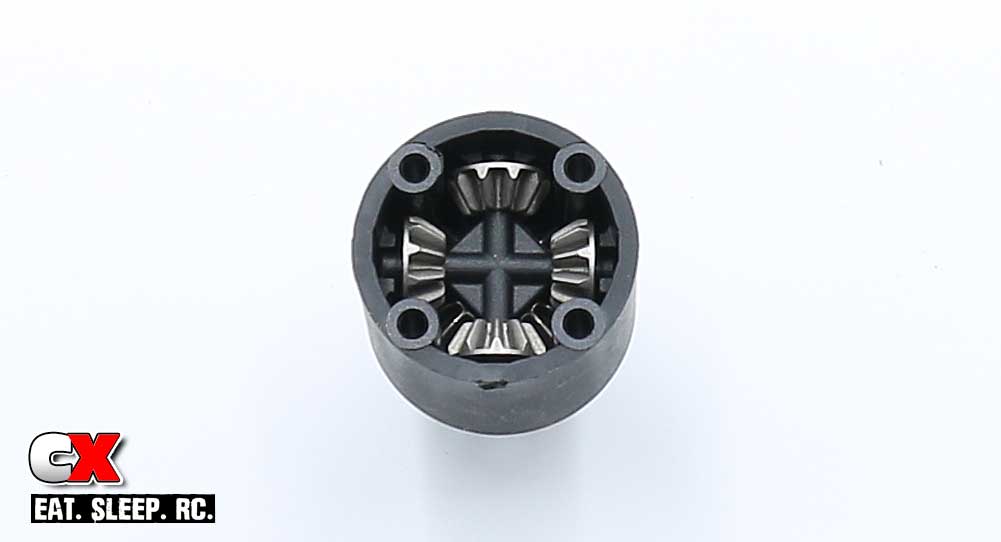
Build the 4-gear satellite assembly and drop it into the diff housing as shown. You may need to wiggle it around slightly to get the gears to correctly mesh.
Step 5:
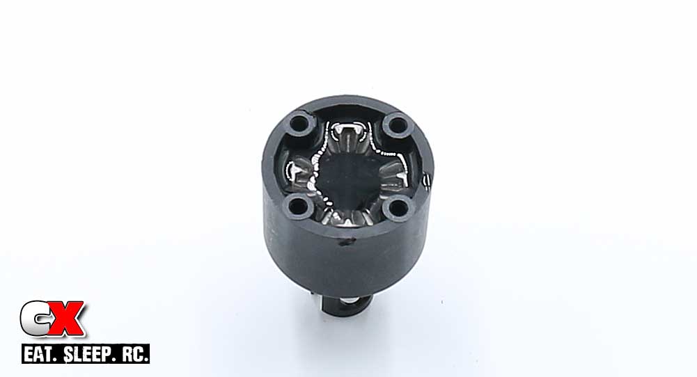
Using the 15K fluid, carefully fill the diff until the fluid is just at the top of the gears. Let it settle for a few seconds and refill if necessary.
Step 6:
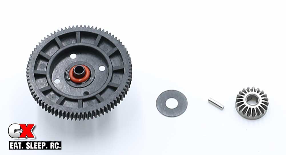
Apply black grease to another outdrive and slide it through the spur gear. Drop the o-ring in place followed by the 14mm shim, chrome pin and sun gear. Again, use a little black grease on the sun gear prior to assembly to help keep it in place.
Step 7:
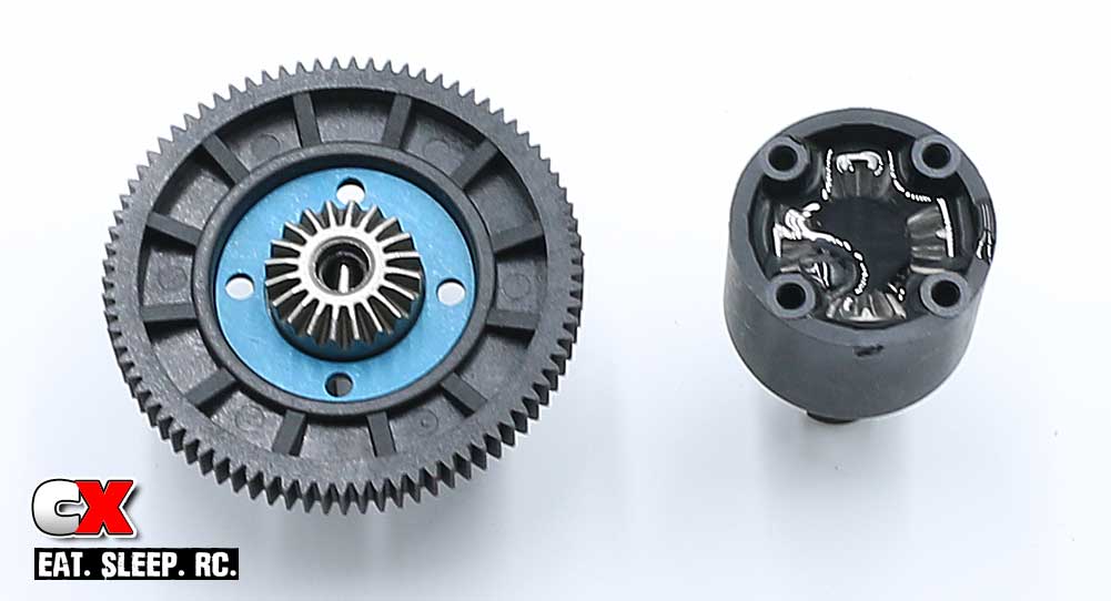
Set the blue gasket into the gear, making sure to line up the holes. Carefully mate the two diff halves together, rotating the outdrives slightly to make sure all the gears mesh correctly. Secure with the M2.5x10mm screws.
Step 8:
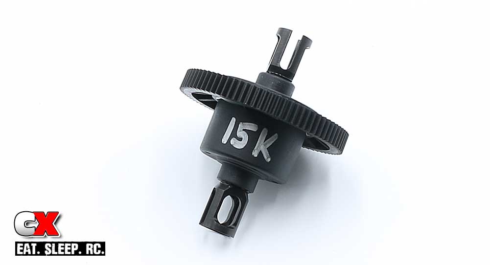
As a final step, I like to write the fluid weight on the outside for future reference.
Step 9:
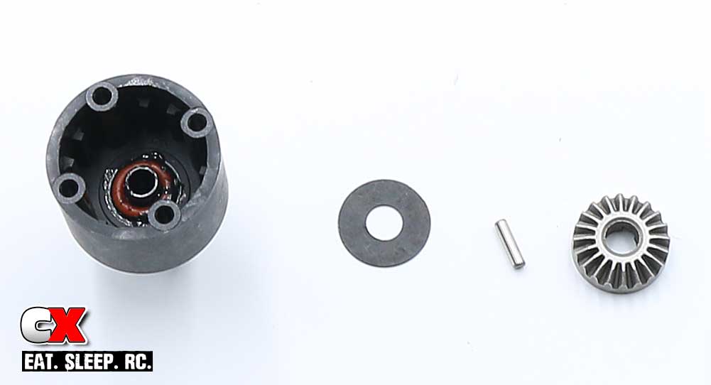
Assembling the front and rear diffs is similar to the center one; add grease to the outdrive, insert into the housing, press the red o-ring into place followed by the 14mm shim, chrome pin and sun gear.
Other than the diff fluid, the front and the rear diffs are identical – you can build both at the same time.
Step 10:
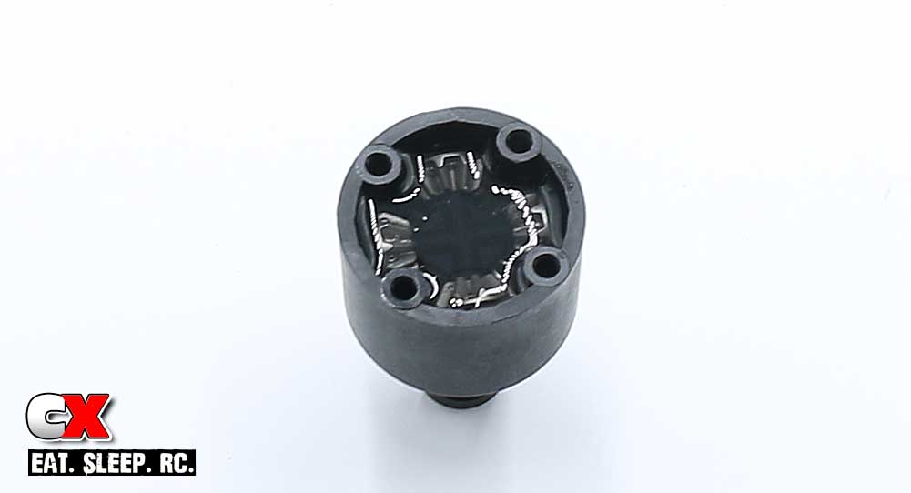
Build the 4-gear satellite assembly, drop into place and fill the housing up with fluid (15K for the front, 7K for the rear).
Step 11:
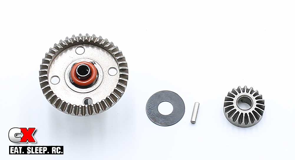
Grease up the outdrive, slide it into the metal diff gear, drop a red o-ring and 14mm shim into place and secure with the chrome pin. Final step is the sun gear.
Step 12:
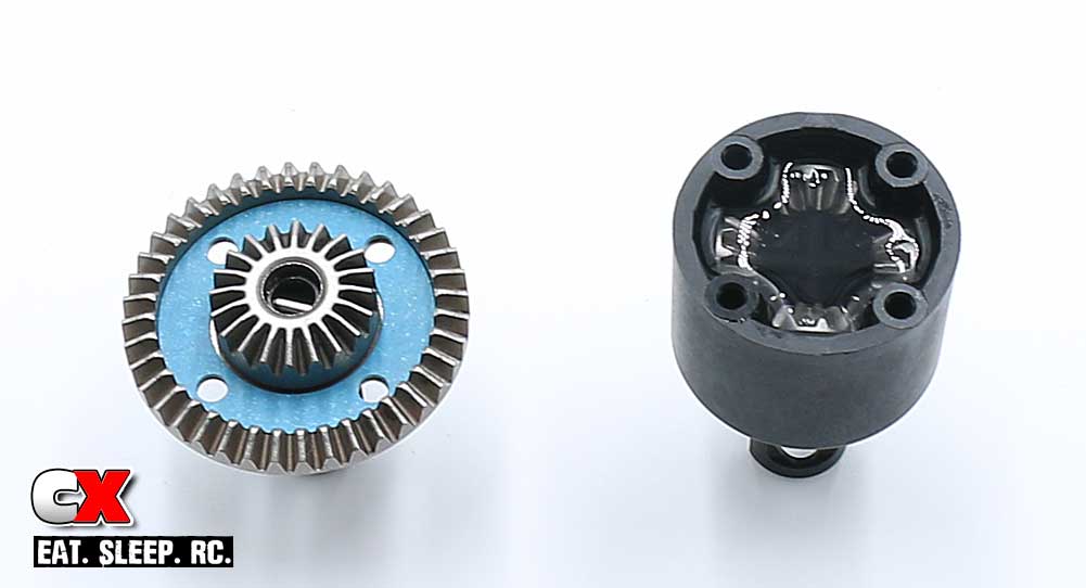
Press and align the blue gasket and mate the two halves together. Again, you might need to rotate the outdrives to get the gears to correctly seat.
Secure the assemblies with the M2.5x10mm screws.
Step 13:
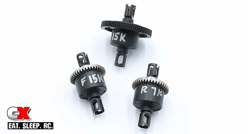
Like the center diff, I write the weights on the front and rear ones as well. Not only is this good for reference, it also makes it easier to discern which diff we need to grab during later assembly.
Clean up any excess fluid with a rag and some motor spray, set them aside and we’re off to the next step.
Tekno RC EB410 Buggy Build – Part 2
The next step in our Tekno EB410 build is the steering system and bulkhead assembly. The EB410 uses a dual bellcrank steering setup that rides on a full set of bearings. The bulkheads are designed to completely encapsulate the diff, using molded plates on the bottom to seal everything up.
Build Notes:
• None for this step.
Step 1:
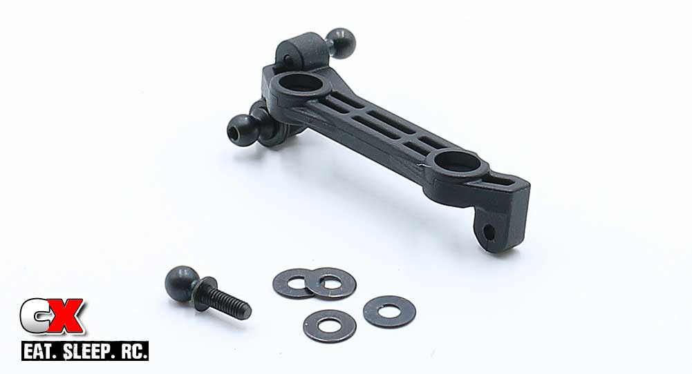
Ok, let’s get started by installing the ballstuds into the steering rack; four 8mm washers are required behind each steering ballstud.
Step 2:
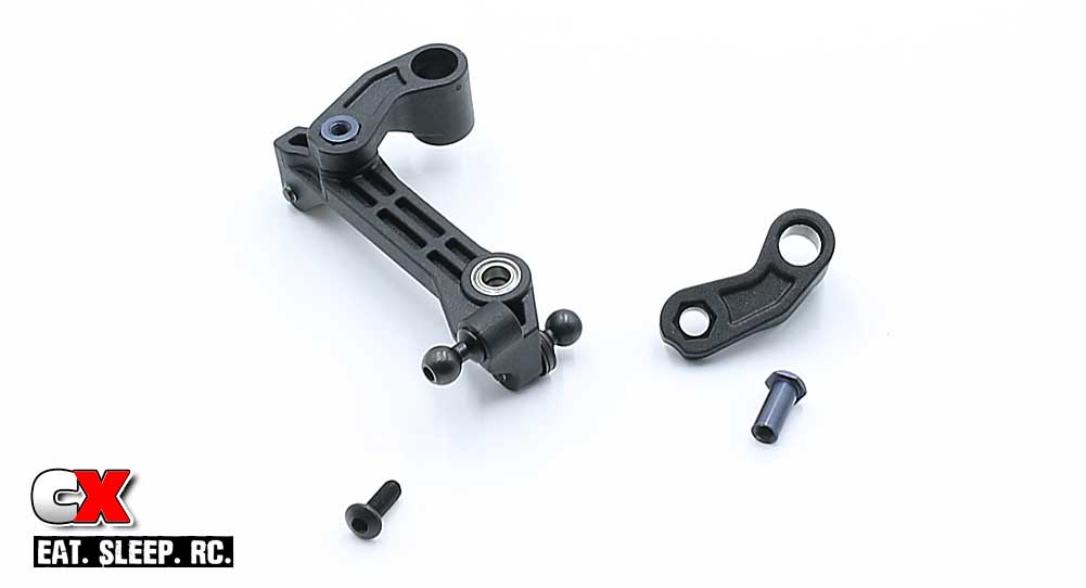
Press a 4×7 bearing into the steering rack, four in total. Slide the aluminum spacers into the bellcrank arms, aligning the hex to the hex in the arm. Insert this assembly into the bearing and secure with the M3x8mm screws. A light dab of the blue threadlocker is suggested. DO NOT overtighten – just snug these screws up. Overtightening can bind the steering movement.
Step 3:
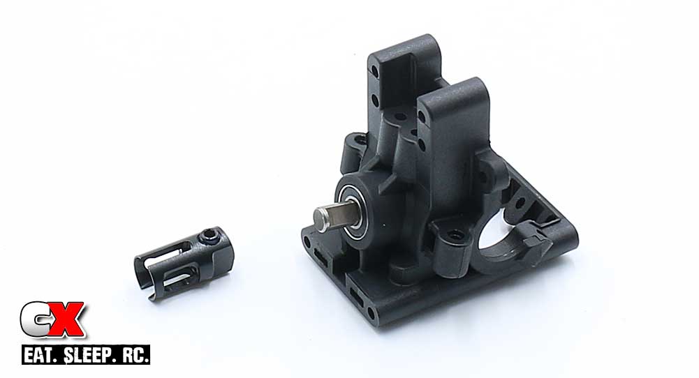
Press a 5×11 bearing into each side of the bulkhead, then slip the output shaft through from the inside. After applying a small drop of blue threadlocker, insert the 4mm grub screw into the outdrive and slide the assembly onto the output shaft. Move the outdrive as far onto the output shaft as possible and tighten down the grub screw.
NOTE: There should be the most minute amount of play between the output shaft and the bulkhead – as small as possible. To close and you could bind the spinning movement of the shaft.
Step 4:
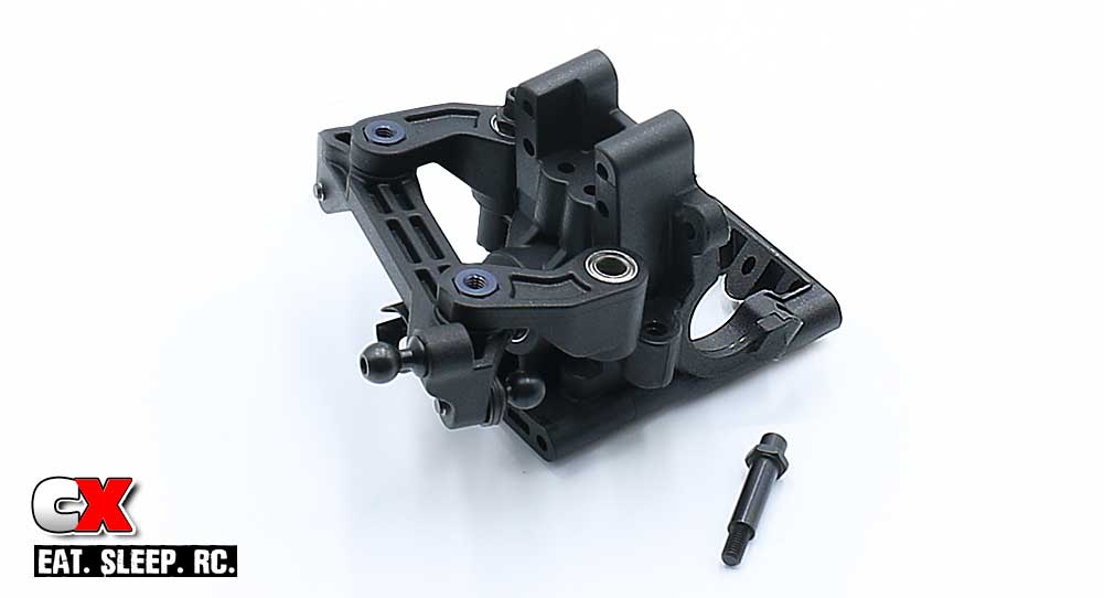
Attach the steering assembly to the front bulkhead with the two steering posts. DO NOT OVERTIGHTEN. Again, snug these up so you don’t bind the steering movement.
Step 5:
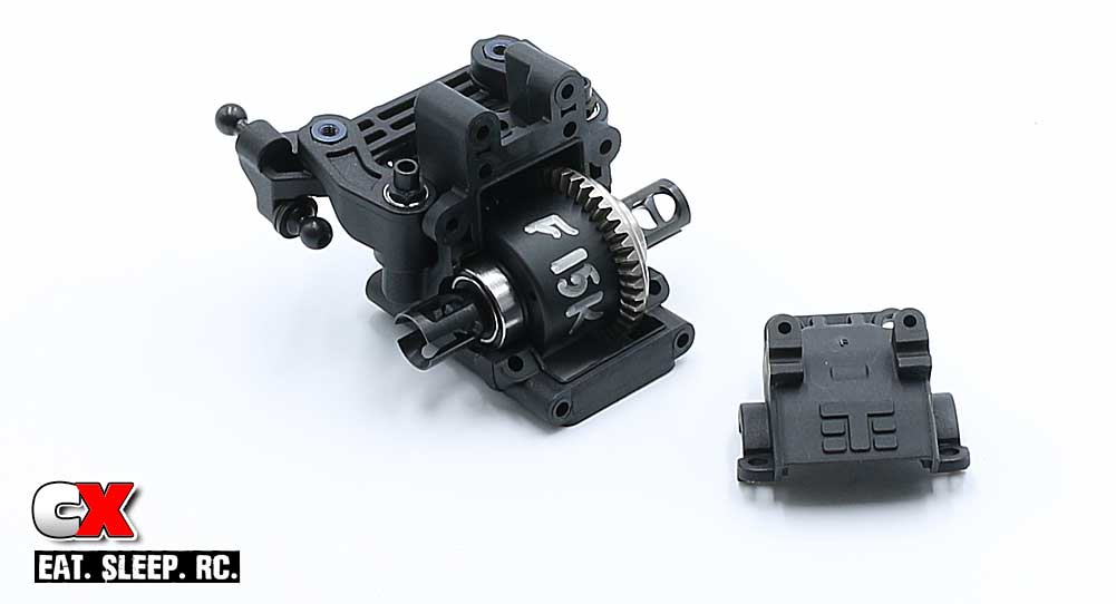
Grab your front diff (you did mark your front diff as such, right?) and attach a 10×15 bearing on each side, then slip it into the bulkhead. Note the orientation.
Verify that it spins freely, then attach the bulkhead cover. A small amount of black grease is suggested on these gears.
Step 6:
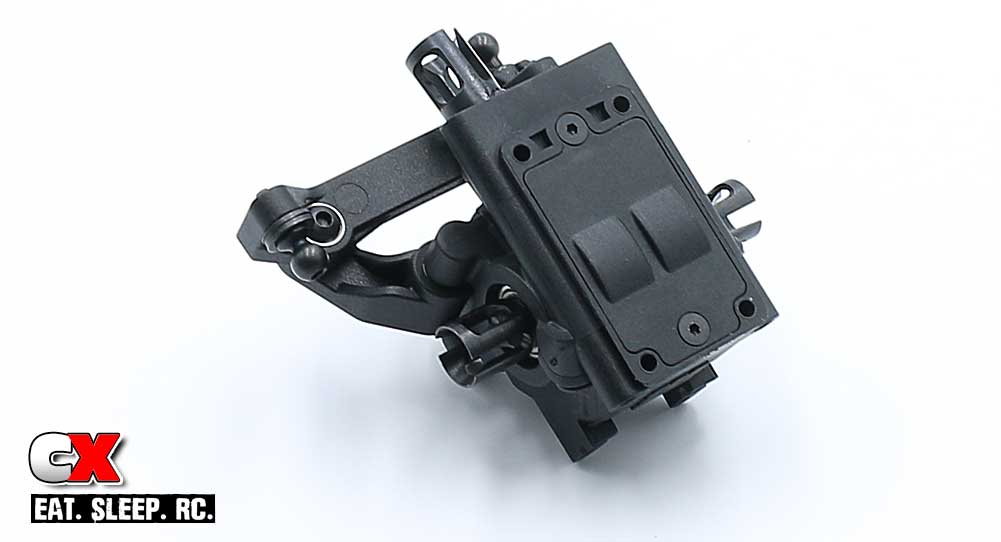
Flip the bulkhead over and attach the bottom bulkhead plate. Set this assembly aside.
Step 7:
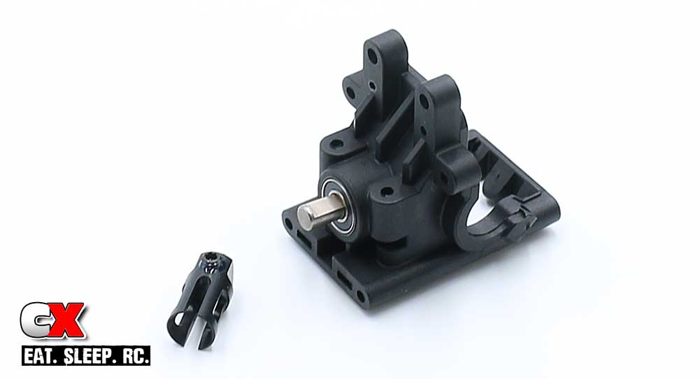
The rear bulkhead assembles like the front; install the two 5×11 bearings, the output shaft and the outdrive. Don’t forget the blue threadlocker on the grub screw.
Step 8:
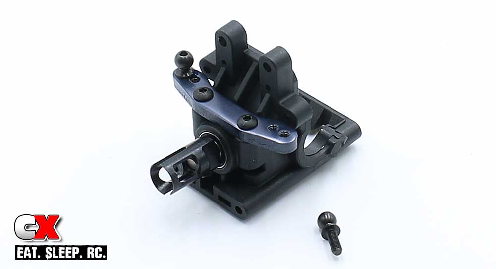
Attach a pair of ballstuds to the aluminum mount (see picture for location) and attach this assembly to the rear bulkhead.
Step 9:
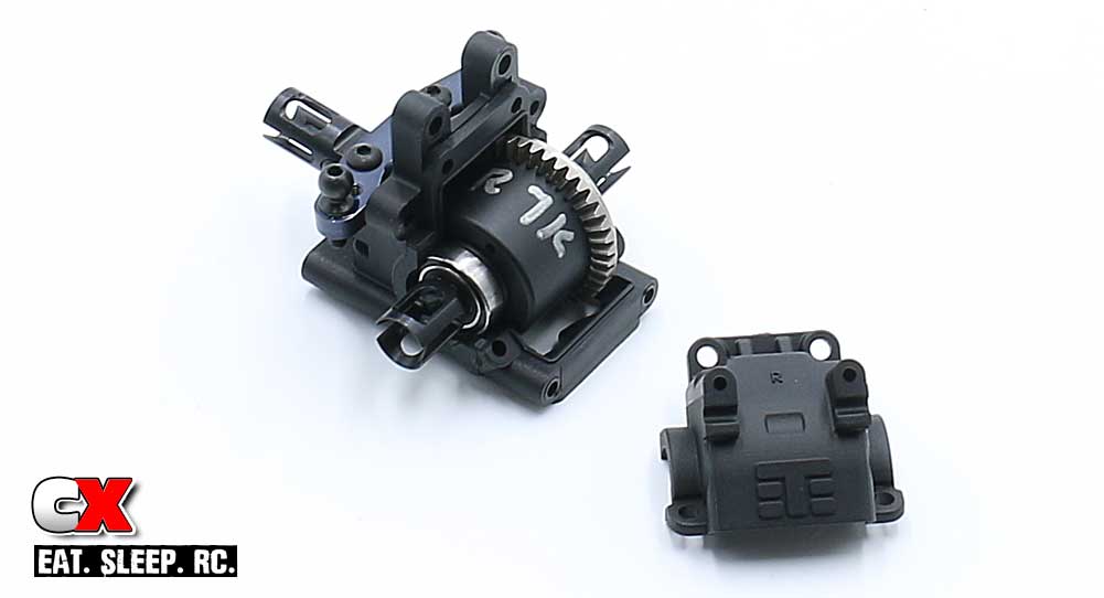
Grab your rear diff and attach a 10×15 bearing onto each side, the slip it into the rear bulkhead as shown. Note the orientation.
Verify that it spins freely, then attach the bulkhead cover. A small amount of black grease is suggested on these gears.
Step 10:
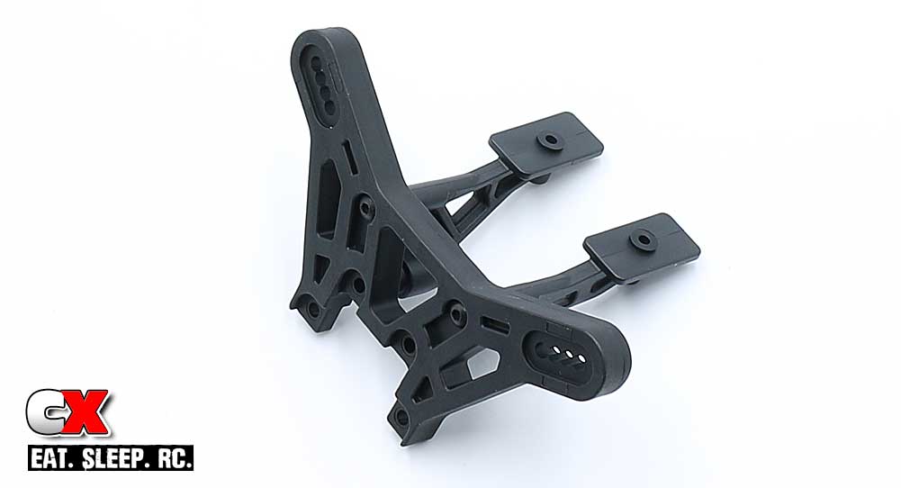
Attach the wing mounts to the rear shock tower.
Step 11:
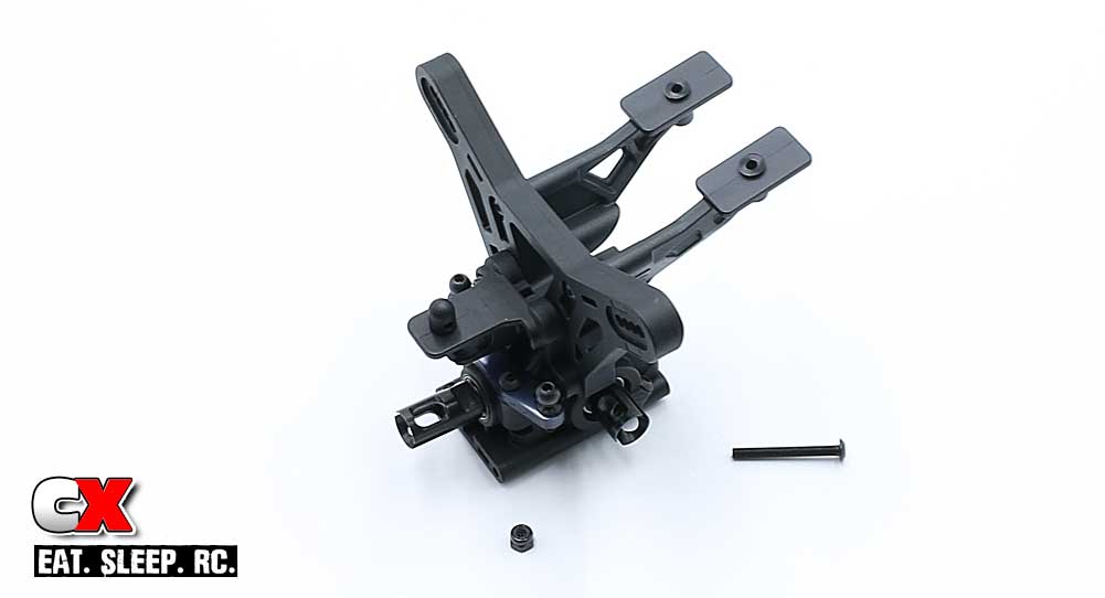
Attach the tower assembly to the rear bulkhead. You’ll need to include the rear body mount in there as well.
Step 12:
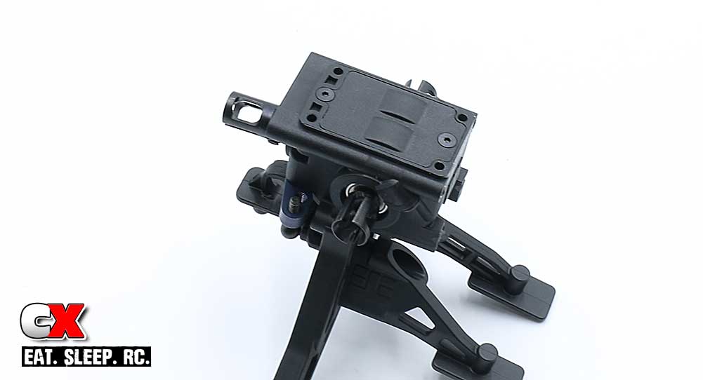
Flip it over and attach the bottom bulkhead plate.
Excellent. As a final check, make sure both assemblies rotate smoothly before moving on to the next step.
Tekno RC EB410 Buggy Build – Part 3
Tekno has us building the rear suspension next; hubs, suspension arms, arm mounts and rear anti-roll bar.
Build Notes:
• There are four arm mounts used with the EB410; A mount, B mount, C mount and D mount. They are arranged as follows: A mount is also known as FF mount, or the Front of the car, Front of the bulkhead. The B mount is also known as the FR mount, or the Front of the car, Rear of the bulkhead.
The C mount is also known as the RF mount, or Rear of the car, Front of the bulkhead. The D mount, also known as the RR mount, is positioned at the Rear of the car, Rear of the bulkhead.
This will help you when assembling the car as to their exact location.
• Tekno’s ballcups are directional, meaning the ballstud can only pop into them from one side. There is a ‘T’ molded into the ballcup; during assembly, make sure the ‘T’ is facing up and you’ll be good to go.
Step 1:
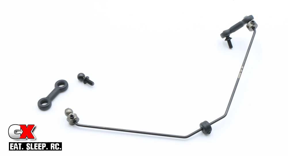
We start off this step by assembling the rear anti-roll bar. Slide the anti-roll bar pivot onto the bar, center it and lock it in place with the 4mm grub screw.
Attach the anti-roll bar ballstuds onto the each end of the bar, lining up the end of the bar with the edge of the ballstud. Lock them in place with the grub screws.
Pop one end of the plastic links onto the 6mm ballstuds and the other end onto the anti-roll bar.
Step 2:
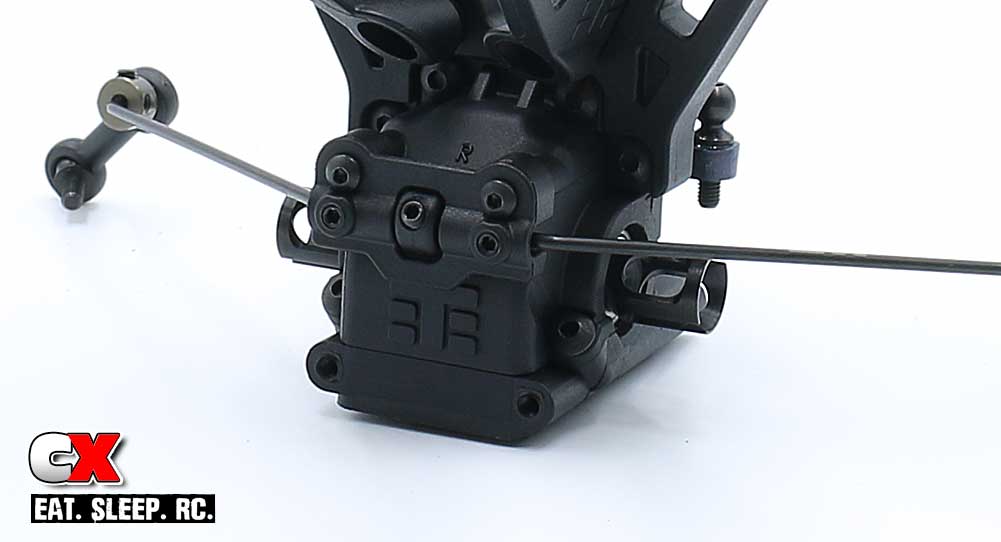
Set the anti-roll bar on the back of the rear bulkhead and attach the anti-roll bar cap to keep the bar in place. Two M2.5x6mm screws secure the cap while the two M3x4mm grub screws should be inserted until they just touch the bar, them back them off a tick. These allow the bar to rotate without hinderance while removing any excess play.
You may need to adjust the pivot to center the bar in the mount.
Step 3:
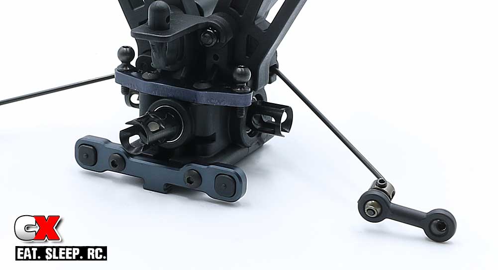
Press the center-dot inserts into the ‘C’ arm mount and attach it to the rear bulkhead assembly.
Step 4:
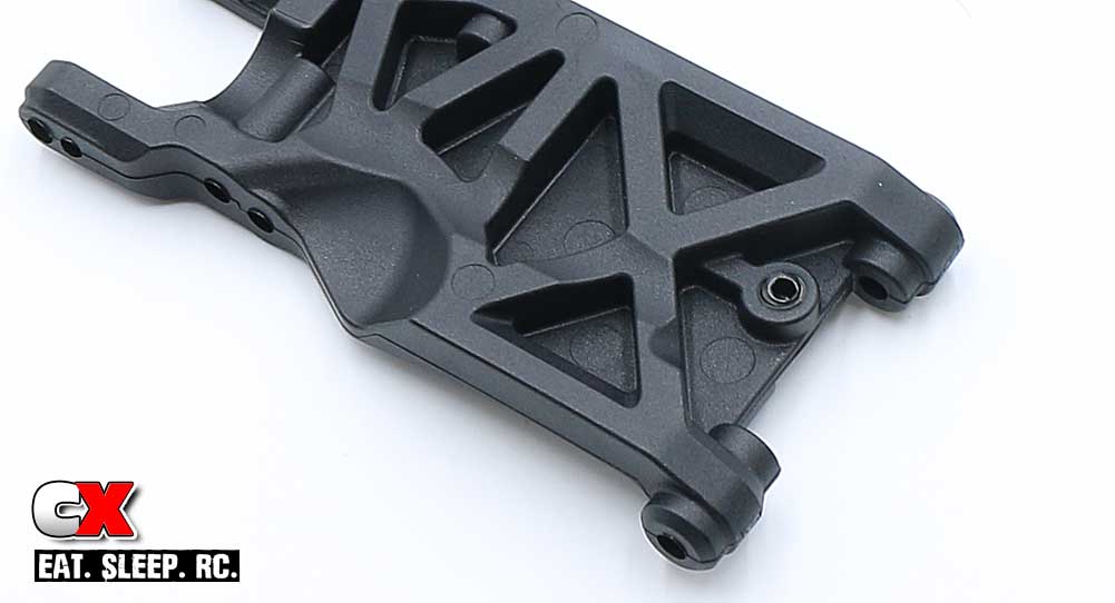
Insert the M4x8mm droop screws into both rear suspension arms. Note the orientation of the screws; they should go through the TOP of the arms.
You can adjust them at the end of the build.
Step 5:
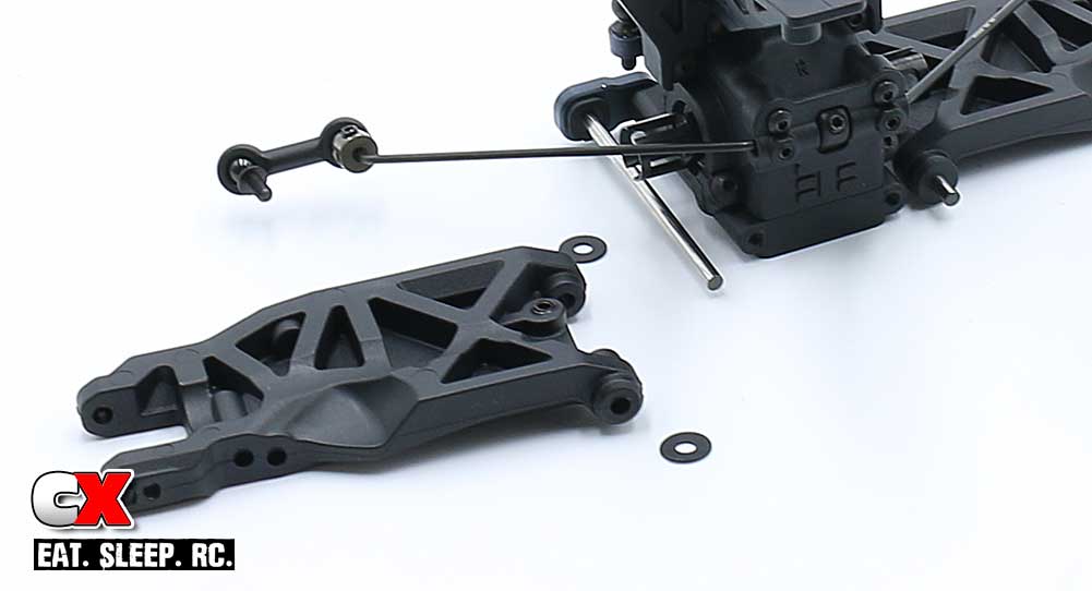
Press the rear hingepins into the ‘C’ arm mount. Slide the 1mm wheelbase shim onto the hingepin followed by the suspension arm and .5mm shim.
Step 6:
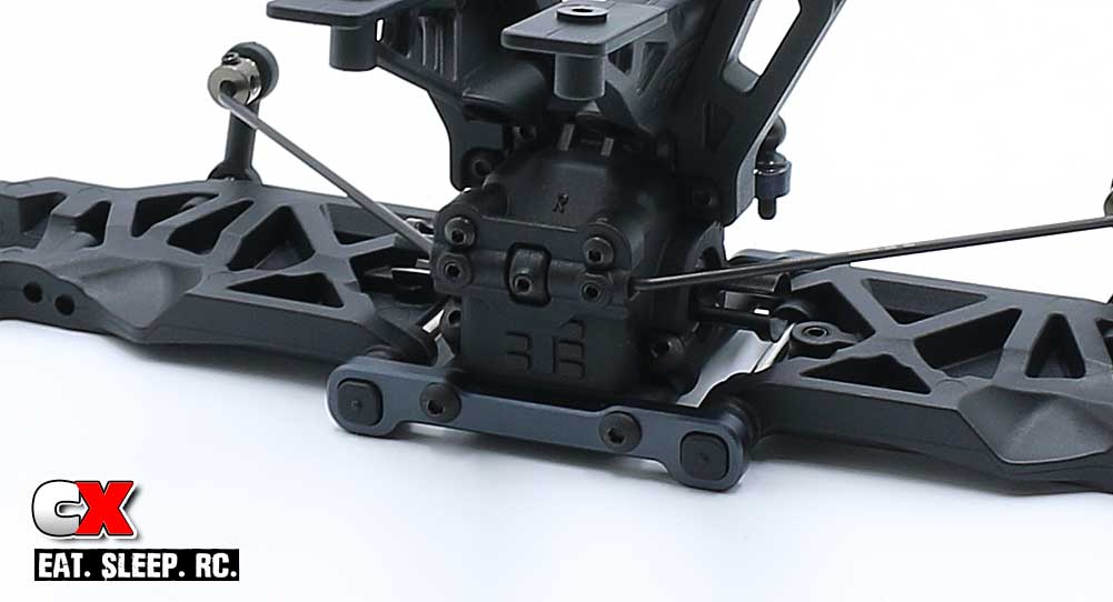
Press the center-dot inserts into the ‘D’ arm mount. Key the hingepins into the inserts and attach the assembly to the rear bulkhead. You can also attach the rear anti-roll bar to the suspension arms.
Move the arms up and down to make sure they swing freely. If the seem sticky, a slight tap on the side of the arm should help free it up.
Step 7:
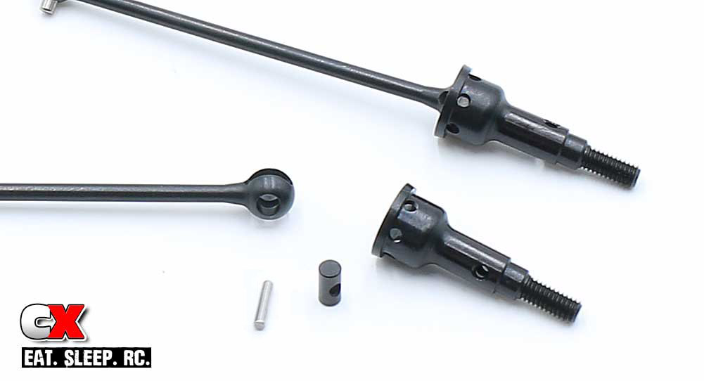
Apply a liberal amount of black grease to the ball of the CVA drives and assemble. Unlike some other drives, there are no grub screws to hold the chrome cross pin in place. This will be addressed in the next couple of steps.
Step 8:
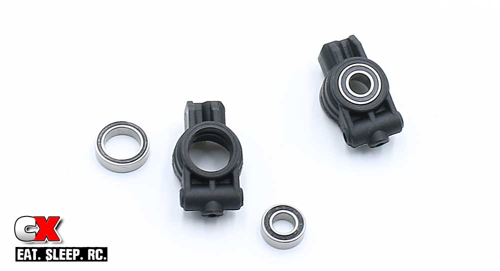
Press a 6×12 and 10×15 bearing into each side of the rear hubs.
Step 9:
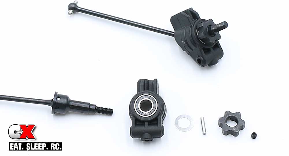
Slide the assembled CVA through the rear hub. Slip the 6x10mm shim onto the axle followed by the chrome cross pin through the hole. Insert the grub screw into the wheel hex, slide the hex onto the axle and, after keying the hex to the cross pin, tighten down the grub screw to secure everything in place.
Step 10:
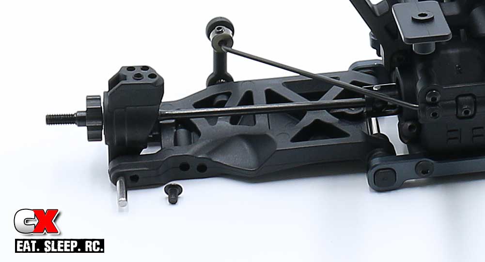
Attach the left rear hub to the left rear suspension arm with the hingepin, securing it with the M3x4mm screw.
Note the orientation of the rear hub. Make sure you are using the left hub on the left side, the right hub on the right side.
Step 11:
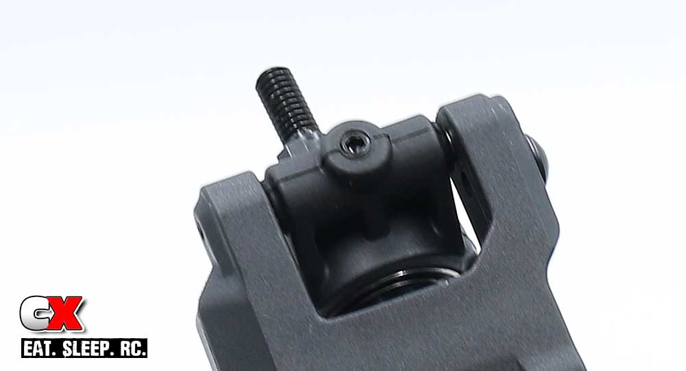
As an extra precaution, thread a grub screw through the bottom of the rear hub. DO NOT OVERTIGHTEN – just snug this little guy up.
Step 12:
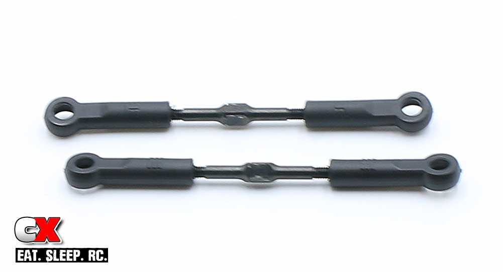
Assemble a pair of rear camber turnbuckles.
Step 14:
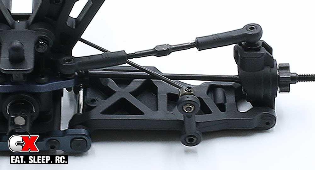
Feed the 8mm ballstuds into the rear hubs, adding two washers under each. Note the hole used in the manual (and pictures).
Pop your assembled turnbuckles into place, making sure that the notches on the links are both facing the left side of the car.
Great job. Your rear bulkhead and suspension are now built and ready to be installed onto the chassis. Get things straightened up and let’s move on to the front suspension.
Tekno RC EB410 Buggy Build – Part 4
The next task in our Tekno EB410 build is the front suspension. This includes the steering knuckles, turnbuckles and extremely burly front suspension arms!
Build Notes:
• Tekno’s ballcups are directional, meaning the ballstud can only pop into them from one side. There is a ‘T’ molded into the ballcup; during assembly, make sure the ‘T’ is facing up and you’ll be good to go.
Step 1:
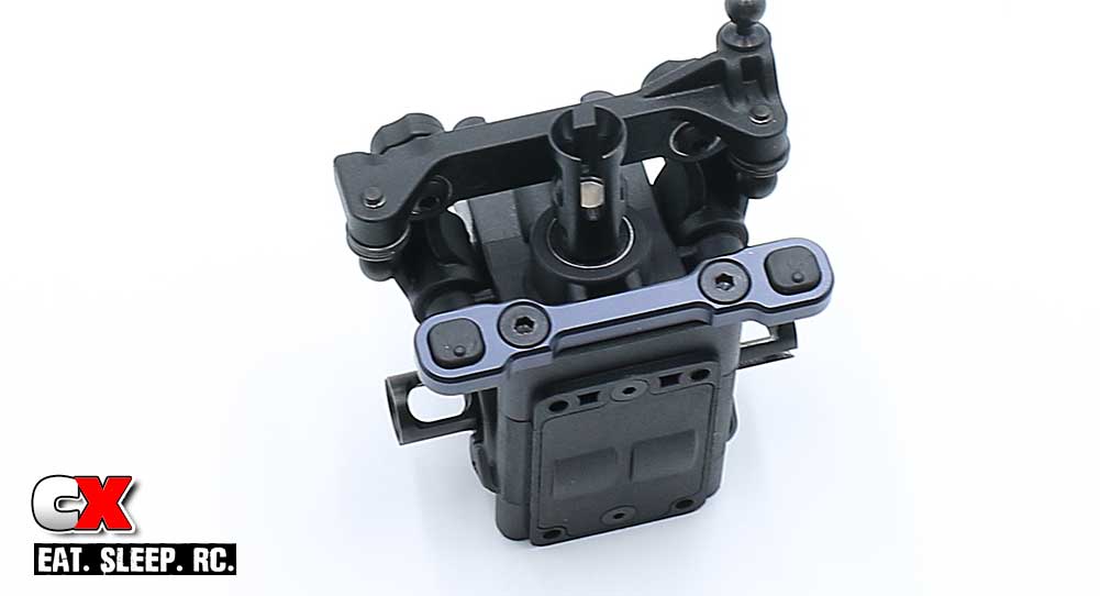
Grab the center-dot down inserts, press them into the ‘B’ arm mount and attach it to the front bulkhead. Note the orientation of the mount; its top/bottom differences are very slight so make sure you have it positioned the right way.
Step 2:
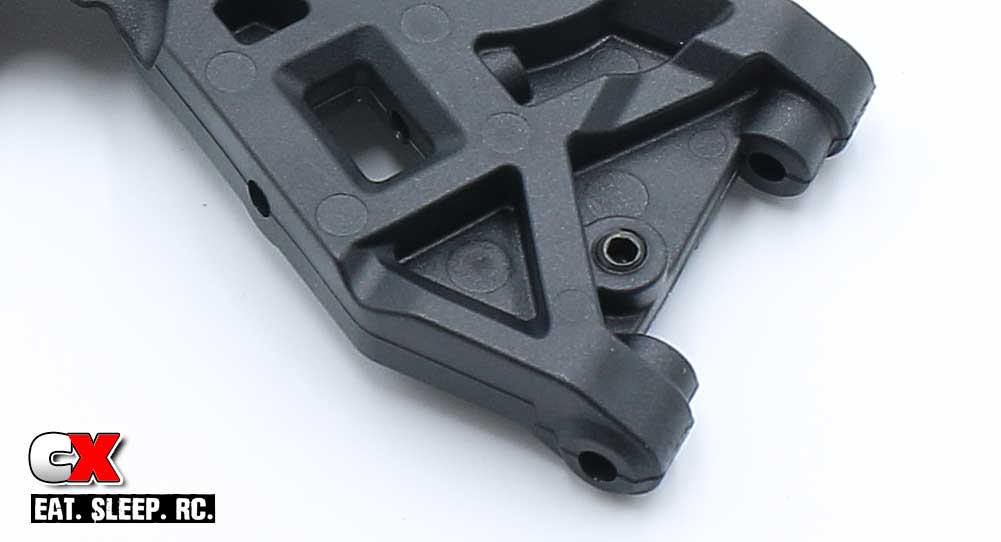
Insert the M4x8mm grub screw through the TOP of the front suspension arms.
You can set the final droop at the end of the build.
Step 3:
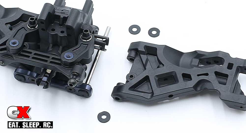
Press the hingepin into the ‘B’ mount followed by a 1mm shim, the suspension arm and 2 .5mm shims. Note the orientation of the front arms; make sure the left arm is mounting to the left side of the car, the right arm to the right side of the car.
Step 4:
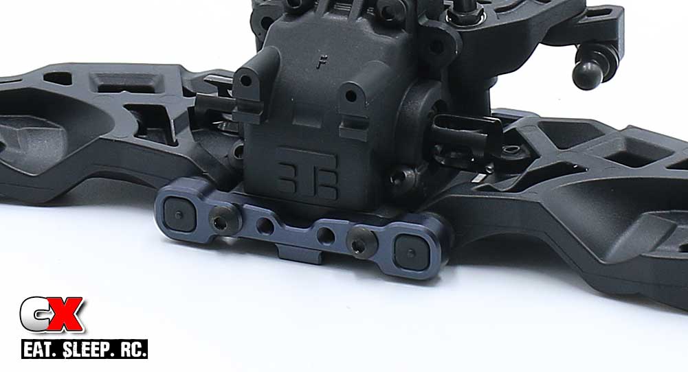
Press the center-dot insert into the ‘A’ arm mount. Fit the ‘A’ arm mount assembly to the front of the car and secure with the M3x14mm screws. Note the orientation of the arm mount in the picture.
Step 5:
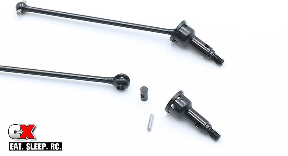
Add a liberal amount of black grease to the ball on the CVA and assemble the drive axles.
Like the rear axles, the fronts don’t require a grub screw to hold the chrome cross pin in place.
Step 6:
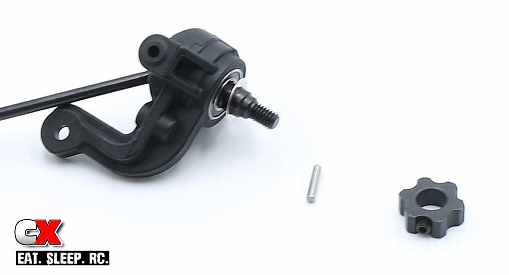
Press a 6×12 and 10×15 bearing into the steering arm. Slide the assembled CVA through the steering arm, then slip the 6x10mm shim onto the axle followed by the chrome cross pin through the hole. Insert the grub screw into the wheel hex, slide the hex onto the axle and, after keying the hex to the cross pin, tighten down the grub screw to secure everything in place.
Step 7:
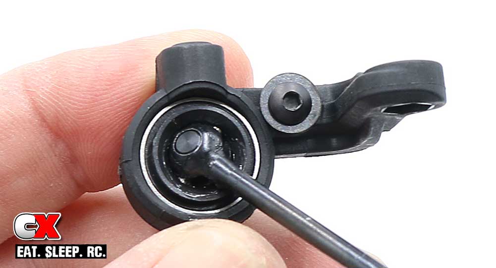
If you’re not paying attention, you can probably miss this step (I did). Insert the M3x4mm screw through two M3x8mm washers and into place on the steering arm.
This is a steering stop screw and help make the car easier to drive. They can be adjusted by the number of washers used; start with the two and experiment as time allows.
Step 8:
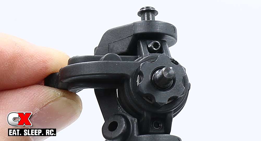
Place the left steering arm into the left caster block and secure with the upper and lower kingpin screws. Using a pair of M3x4mm grub screws, carefully thread them into the holes as shown until they come in contact with the kingpin screws. I say carefully because they don’t need to be tight, just enough to make contact.
Step 9:
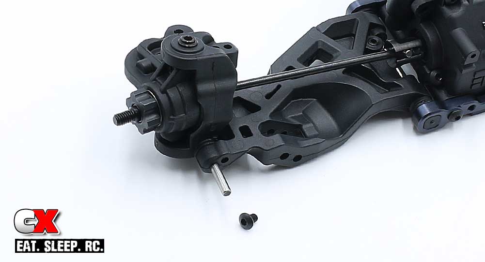
Attach the steering assembly to the suspension arm, using the hingepin as the swivel point. The M3x4mm screw is used to keep the hingepin in place.
Make sure you attach the left assembly to the left side of the car, the right to the right side.
Step 10:
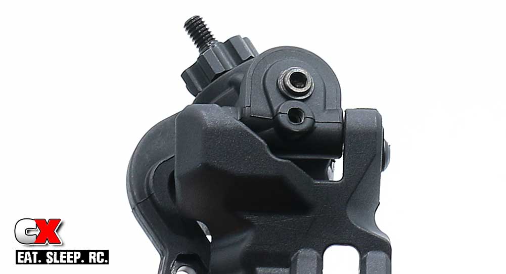
As a backup, Tekno includes M3x4mm grub screws that feed into the bottom of the steering assembly. DO NOT OVERTIGHTEN – snug is the way to go here.
Step 11:
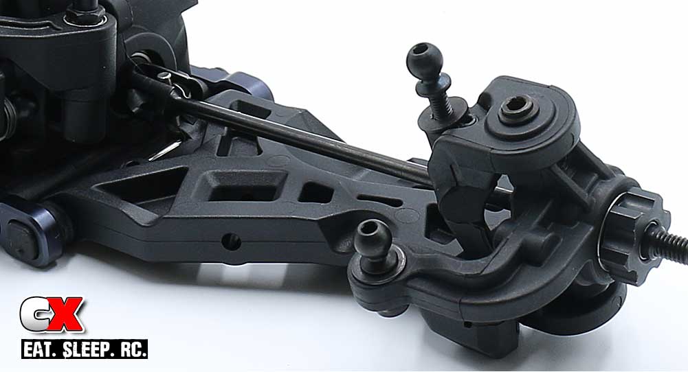
Final assembly on the steering arms; feed the 8mm ballstud through the steering arm and capture it with the M3 locknut. Don’t forget to use a M3x8mm washer.
Before installing the 8mm ballstud into the inside hole on the caster block, insert the M3x4mm grub screw into the outer hole first. This helps keep the screws holes from deforming during use. Don’t forget the M3x8mm washer under the ballstud.
Step 12:
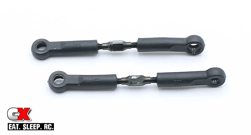
Build a pair of steering turnbuckles.
Step 13:
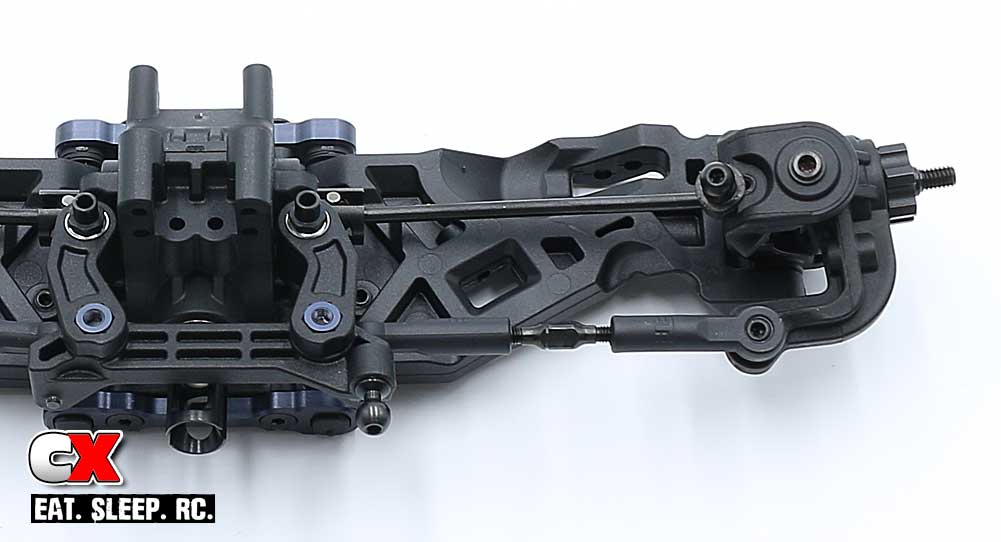
Connect the steering turnbuckles as shown. Make sure the notches on the links are pointing to the left side of the car.
Step 14:
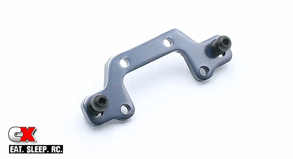
Assemble the front ballstud mount. Use the upper hole as shown.
Step 15:
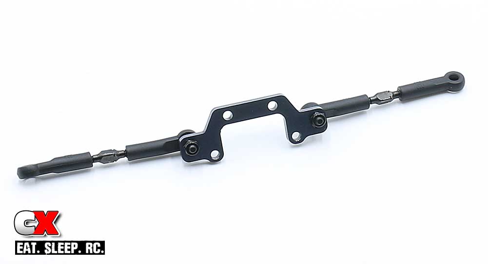
Build a pair of camber turnbuckles and attach them to the ballstud mount. Again, make sure the notches on the turnbuckles are pointed to the left.
Step 16:
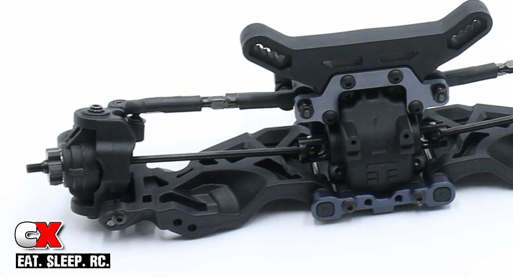
Attach the ballstud mount and front shock tower to the front bulkhead. Pop the free end of the turnbuckles onto the ballstuds on the caster blocks.
Another fine job. Your front bulkhead and suspension is now built and ready to be installed onto the chassis. Take a moment to clean up your area and get ready for the next step.
Tekno RC EB410 Buggy Build – Part 5
In Part 5 of our Tekno EB410 build, we’ll be attaching assemblies to the beautiful chassis. This includes the front and rear clips, center diff and all the miscellaneous bits that hold these pieces together.
Build Notes:
• In Step 3, the manual shows the chassis brace being installed before the center bulkheads. Because the brace surrounds the front drive axle, it was a bit challenging to get this all in place. I rearranged the build slightly to make it easier. You’ll see what I mean.
Step 1:
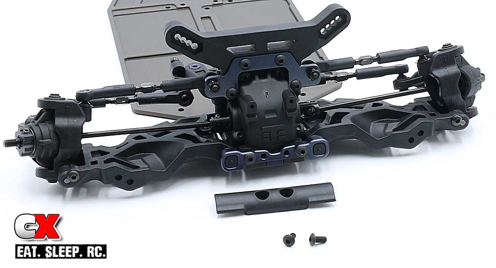
Using two M3x10mm and two M3x8mm screws, attach the front end assembly to the chassis. Once secure, attach the front bumper.
A small dab of the blue threadlocker on the bumper screws is suggested.
Step 2:
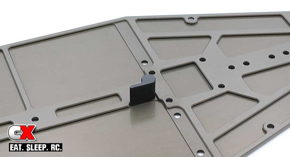
Attach the battery stop…
Step 3:
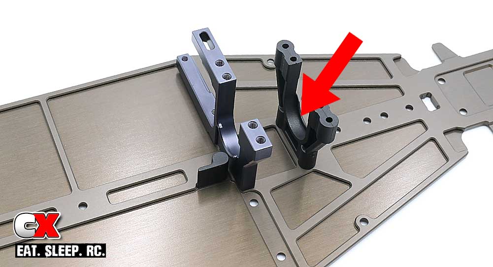
…followed by the aluminum and plastic center bulkheads. Note the direction of the plastic bulkhead.
Step 4:
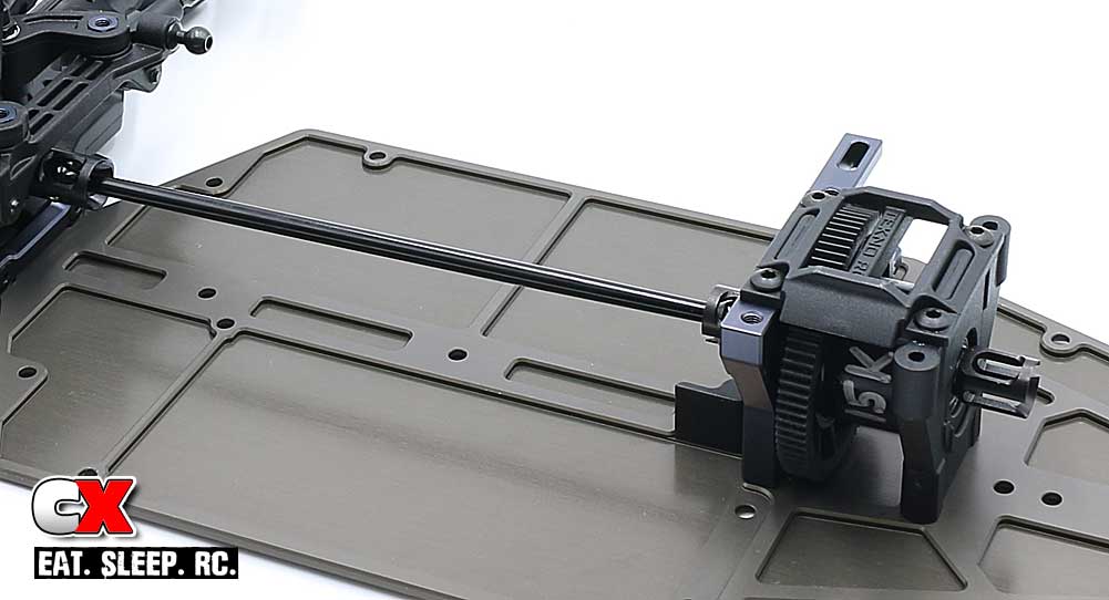
Press a 10x15mm bearing onto each side of your center diff followed by the plastic diff wedges. As the instructions show, make sure the rounded edge of the wedges are pointing down.
Align the front drive axle into the front bulkhead outdrive and center diff and drop the diff into place. Make sure the diff is seated correctly; you can check this by rotating the drivetrain. It should be buttery smooth without any binding.
Attach the center bulkhead cap, using blue threadlocker on the two M3x8mm screws that feed into the aluminum.
Step 5:
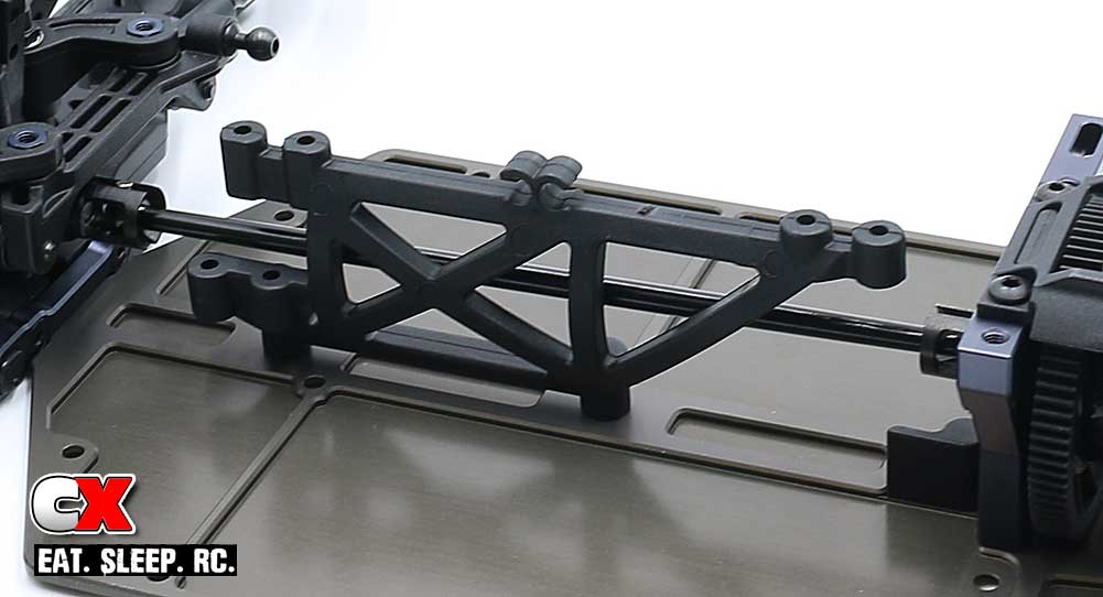
Attach the plastic chassis brace.
Step 6:
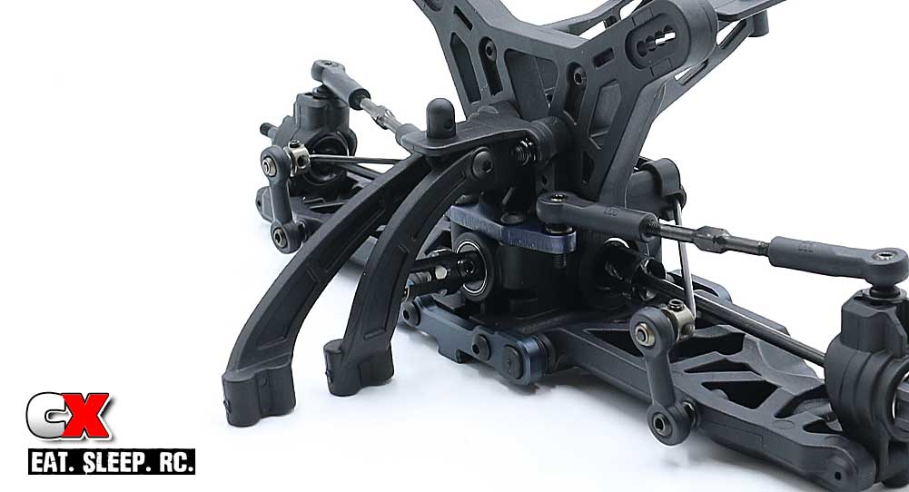
Attach the two chassis braces to the rear bulkhead.
Note: For the kit build, you will use the inserts with the hole in the UP position. If you decide to run either (or both) of the bulkhead risers, you will need to adjust these risers accordingly.
Step 7:
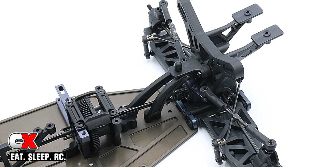
Align the rear drive axle into the rear bulkhead outdrive and center diff and attach the rear bulkhead assembly to the chassis with eight of the M3x10mm screws.
Check the drivetrain for binding by rotating it a few times. If it seems a little tight, that’s ok; Tekno has stated that the gear mesh might be tight for the first couple of battery packs.
WOO HOO! It’s all starting to come together! Clean off some space and get ready for the next step – the shocks!
Tekno RC EB410 Buggy Build – Part 6
The shocks on the Tekno EB410 are fantastic. They use 13mm hard-anodized bodies, 3.5mm shafts and a unique x-ring cartridge that prevents leakage. Once built, these are some of the silkiest dampers on the market!
Build Notes:
• Since we’ll be dealing with shock fluid, building the shocks can sometimes be a messy step. Make sure you have a clean, covered workspace and plenty of rags or towels on hand to clean up any excess fluid. Motor spray (or similar) is also suggested to help remove any excess fluids from the shocks themselves.
• You’re going to need a shock stand handy for this step. I’ve used quite a few over the years, but the one from Vison Racing Products is probably one of my favorites. You can check it out here: VRP CNC 1:10th Off Road Ultra Shock Stand
Step 1:
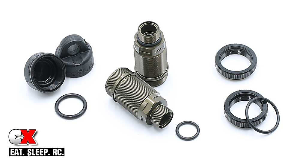
When it comes to shocks, my first step is to install all of the o-rings first; small ones on the bottom of the shock, mid-size in the caps and large ones in the threaded collars. This can become a challenge if you get any fluids on your fingers (then on the o-rings), so doing this first ensures a dry install.
Step 2:
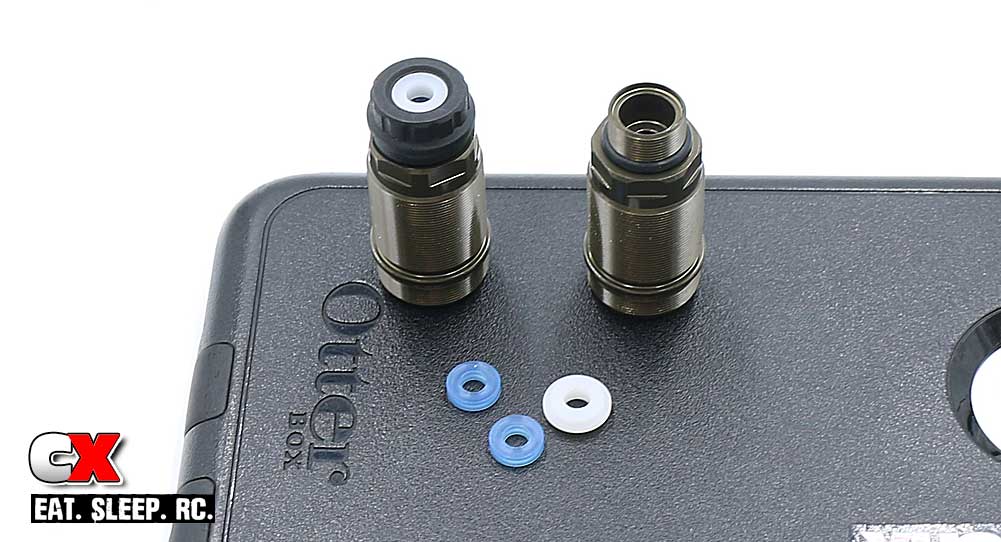
Build the lower cartridges on the two front shocks. This consists of a pair of the blue o-rings and the white spacer. Capture the parts with the lower shock cap.
Step 3:
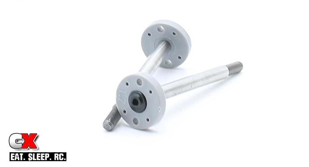
Attach the 1.7mm pistons to the front shock shafts. A very light dab of blue threadlocker is suggested here.
Step 4:
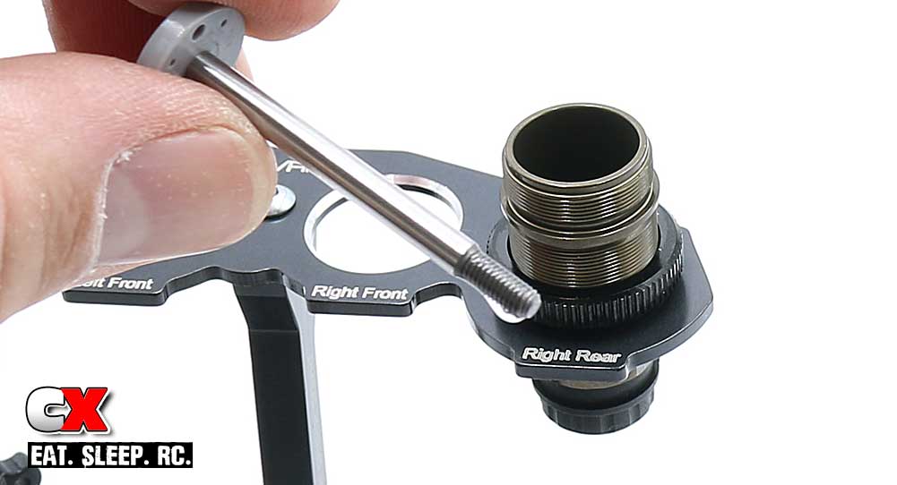
Place a small drop of shock fluid on the threaded part of the shock shaft and insert into the front shock bodies. Insert slowly so you don’t damage the cartridge o-rings.
Step 5:
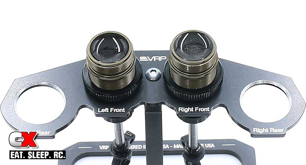
Pop an eyelet ball into each lower shock eyelet and thread it onto the shock shaft. Attach the threaded collars.
Fill the shocks with fluid until it’s about 1-2mm from the top, then slowly plunge the shock shaft up and down a couple times. You should see air bubbles release from under the piston and start rising to the top. Set aside in your shock stand for a few minutes until all the bubbles are gone.
Step 6:
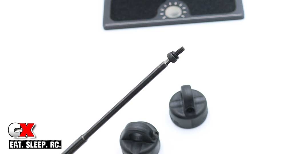
While we’re waiting for the bubbles in the shocks do dissapate, let’s pre-tap the bleeder shock caps.
Install the itty bitty, teeny weeny black o-rings over the M2x4mm screws as shown. Thread the screws into the cap until they bottom out, then remove.
Now, PATIENCE is key here when installing the little o-rings. I’ll warn anyone with chubby fingers – you’re going to lose your sh*t trying to make this happen. Get your kids, wife, mail carrier – ANYONE WITH SMALL FINGERS – to help you out here if possible. Or, if you’re like me, I treated myself to a bowl of ice cream after completing JUST this step.
As a tip, Trying putting the screw onto your wrench while working with the o-ring. It does make it quite a bit easier.
Step 7:
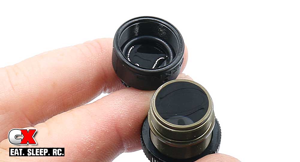
The bubbles in your shocks should now be gone. Fill the shock until the fluid is level with the top of the body, then add 2-3 drops of oil into the cap.
Step 8:
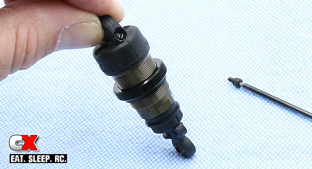
Screw the cap onto the shock and, on a absorbant base (like a towel or rag), compress the shock all the way. You should see some oil filter out through the bleeder cap.
While compressed, insert the bleeder cap screw.
Step 9:
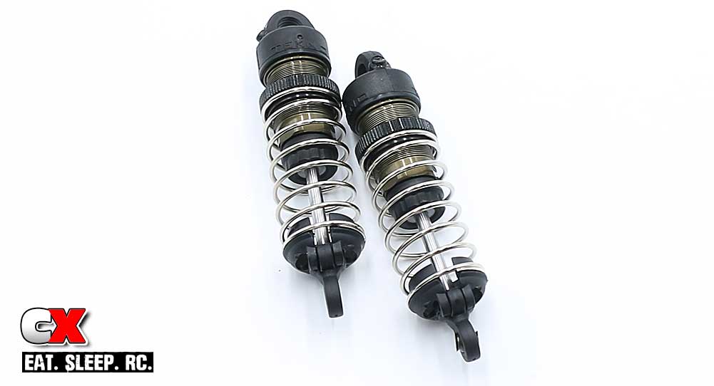
Clean off any excess fluid on the outside of the shock (here’s where the motor spray comes in handy). Slide the front springs onto the shocks followed by the spring retainers. You’ll notice the retainers key into the rod ends; use the M3x8mm grub screw to connect them together.
Step 10:
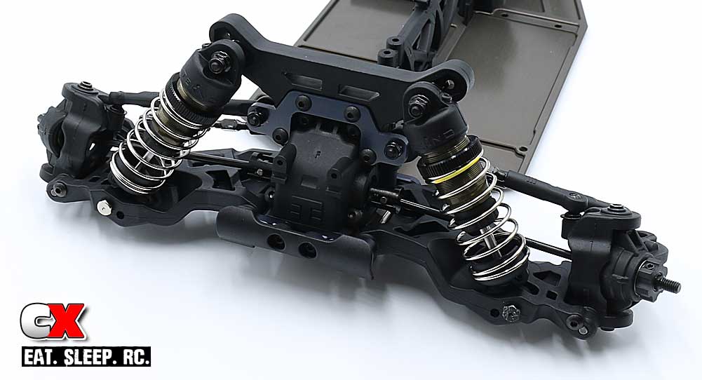
Attach the shock hardware to the front tower; third hole in from the top. Set the shocks in place and secure with the M3 locknut (up top) and the M3x18mm shock mount screws in the arm.
Note: Tekno supplies the EB410 with left and right thread shock mount screws. The black screw has right-hand threads; it goes on the left side of the car. The chrome screw has left-hand threads; it goes on the right side of the car.
This helps prevent the screws from backing out as the suspension moves up and down.
Step 11:
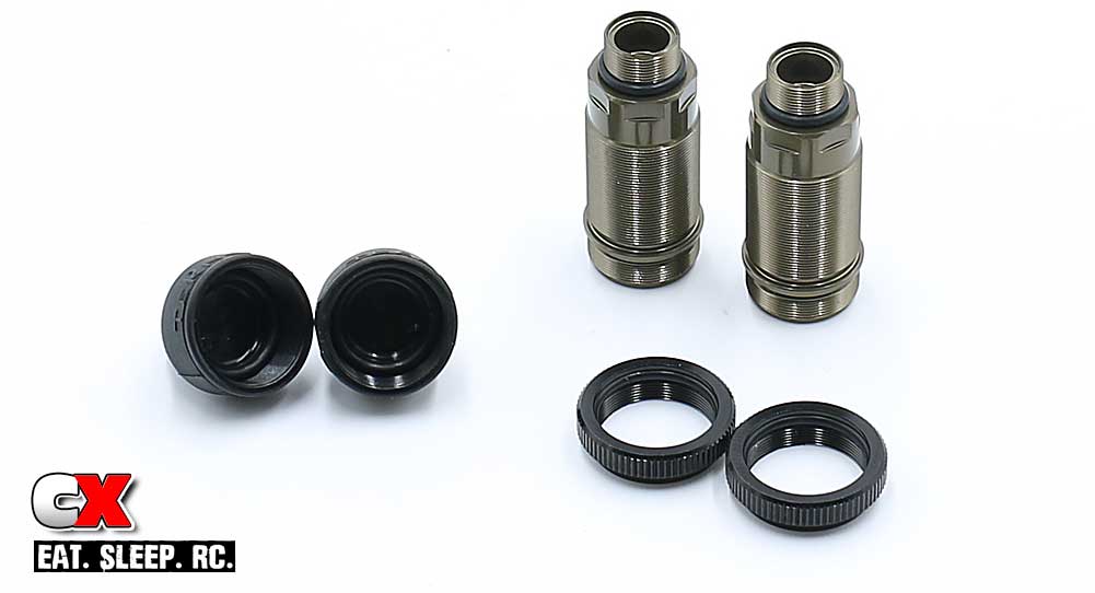
On to the rear shocks. The procedure is the same as the fronts; start by installing all the black o-rings.
Step 12:
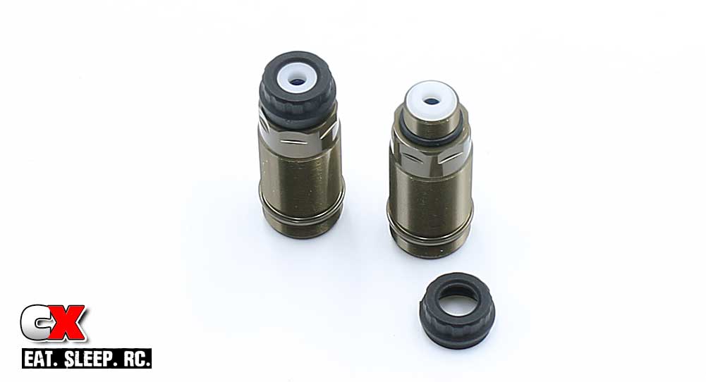
Build the lower cartridges.
Step 13:
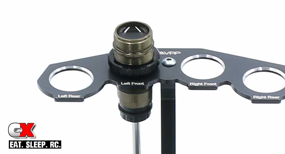
Add a drop of oil on the shock shaft and install. Pop an eyelet ball into each lower shock eyelet and thread it onto the shock shaft. Attach the threaded collars. Fill with oil and plunge up and down to remove any bubbles. Set aside in your shock stand.
Step 14:
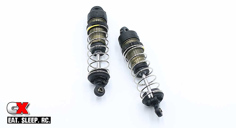
Add the baby o-rings to the M2x4mm screws and pre-tap the caps. Fill the shocks with fluid until it is level with the body, add 2-3 drops into the cap and assemble. Compress, bleed and add the M2x4mm bleeder screws.
Add the springs, retainers and M3x8mm grub screws.
Step 15:

Add the shock mounting hardware to the tower (third hole in), attach the shocks and secure with the M3 locknuts and M3x18mm shock mounting screws.
Again, Tekno supplies the EB410 with left and right thread shock mount screws. The black screw has right-hand threads; it goes on the left side of the car. The chrome screw has left-hand threads; it goes on the right side of the car.
Awesome job on the shocks! Set your almost-completed EB410 aside and let’s get crackin’ on the final assembly stuff.
Tekno RC EB410 Buggy Build – Part 7
In this step of the Tekno EB410 build, we’ll be installing all the final parts to finish up the car; motor mount, steering links, velcro body mounting, etc. We won’t be showing the electronics just yet; that will be in the reveal video.
Build Notes:
• Tekno’s ballcups are directional, meaning the ballstud can only pop into them from one side. There is a ‘T’ molded into the ballcup; during assembly, make sure the ‘T’ is facing up and you’ll be good to go.
Step 1:
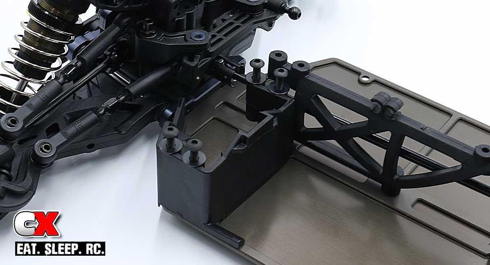
The first thing you need to determine before starting this step is if you’re going to be using a standard or shorty steering servo. Tekno supplies a different mount for each.
Once you have that figured out, go ahead and attach that mount to the chassis.
Step 2:
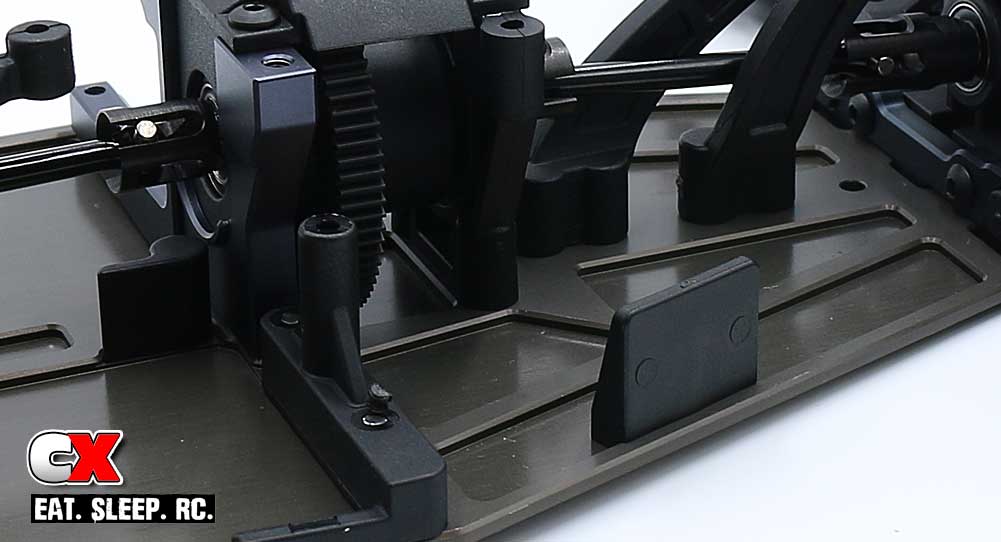
Attach the rear battery mount and Velco body-mounting tab.
Step 3:
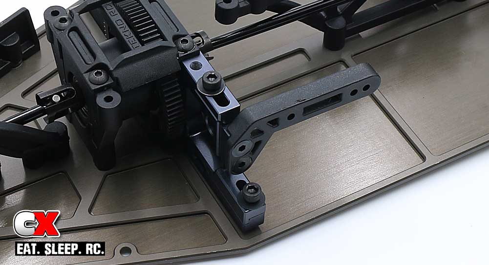
If you’re going to be using a fan, attach the fan mount to the motor mount, then slide this assembly onto the chassis. Lock in place with the pair of M3x10mm screws.
Step 4:
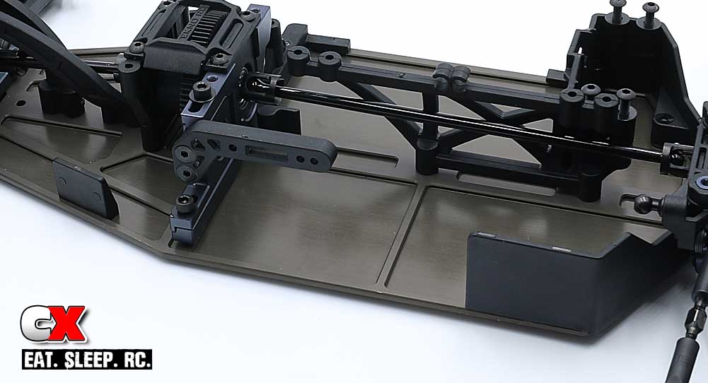
Attach the front dirt shield and rearward Velco body-mounting tab.
Step 5:
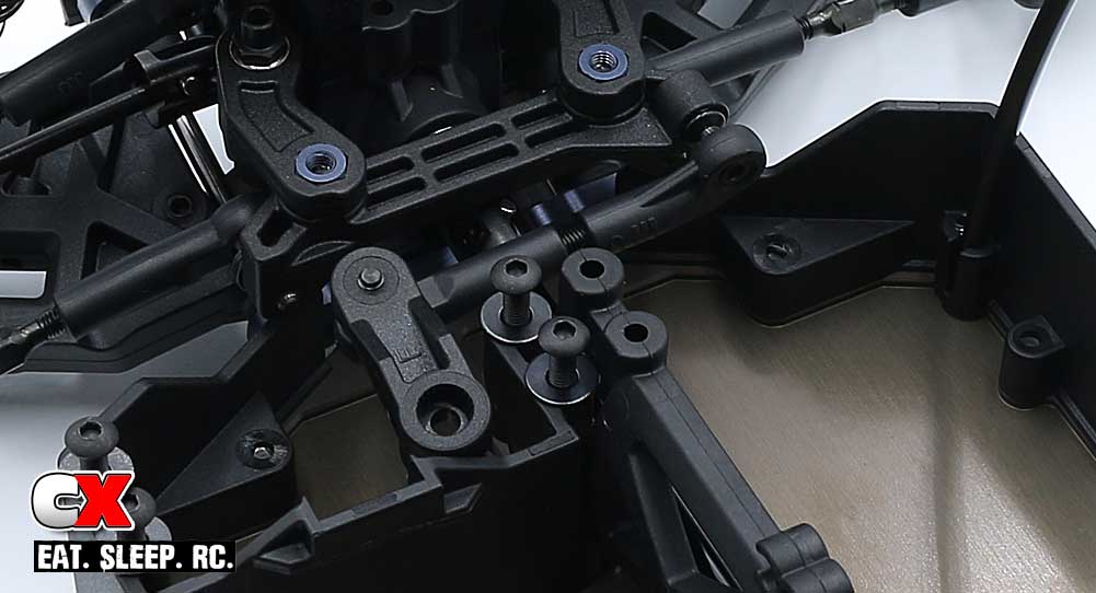
Build the servo horn. Tekno supplies different horns depending on the tooth count of your servo.
Build the drag link and attach it to the servo horn and ballstud on the steering rack.
Step 6:
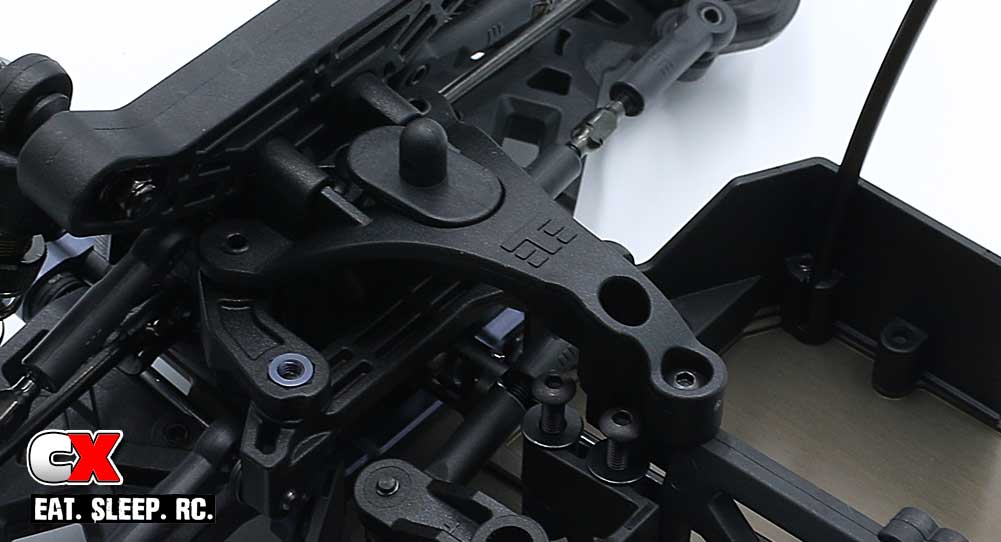
Attach the front body mount to the top brace and install that assembly to the front of the car.
Step 7:
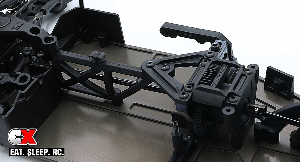
Attach the center top brace. A small dab of blue threadlocker is suggested on the M3x8mm screws feeding into the aluminum mount.
Step 8:
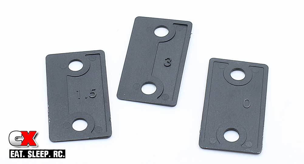
Tekno supplies three optional rear wing wedges; a 0°, 1.5° and 3°. These can be used to tilt the rear wing up for added rear grip. I’ll be starting off with the 0° wedge.
Step 9:
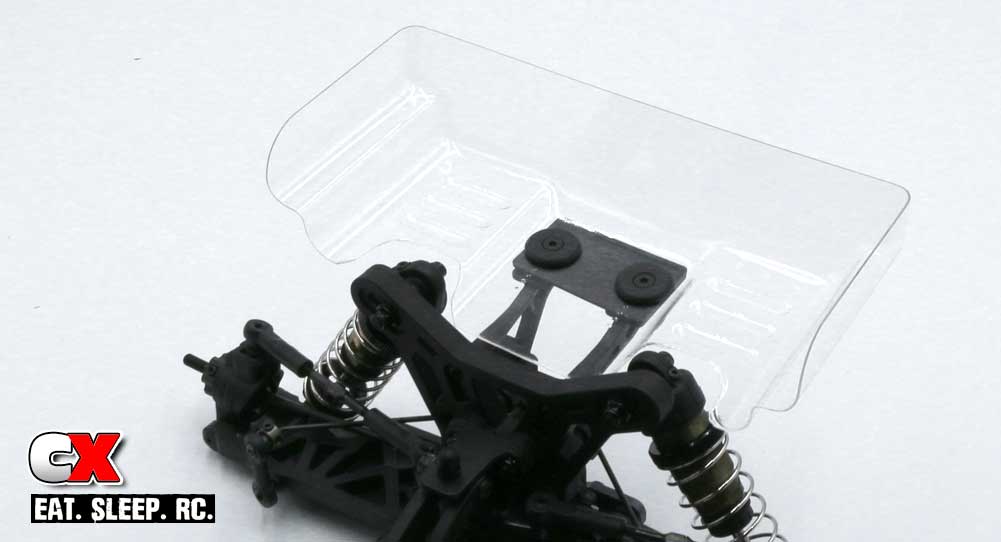
Drill a pair of small holes in the rear wing and attach it to the wing mounts (don’t forget the wedge).
Step 10:
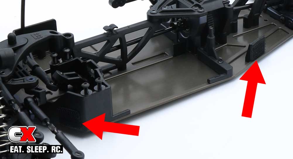
Tekno also supplies some Velcro to help keep the body on. The red arrows show the designated places for it to go (on both sides of the buggy).
After you paint the body, you can stick the other half of the Velcro to the body (there are markings as to where it goes).
Step 11:
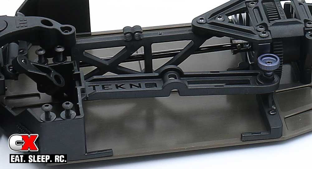
Install the M3x18mm grub screw into the rear battery mount, insert the battery strap and secure with the aluminum battery thumbscrew. Don’t forget to press the o-ring over the thumbscrew.
Boom – done and done! Your EB410 is now ready for electronics.
While we usually show the electronics installed in our builds, the EB410 was a special case and had the fellas over at R1 Wurks do the install for us. To see what they did, check out our reveal video.

