
Team Associated B64 Club Racer Online Build
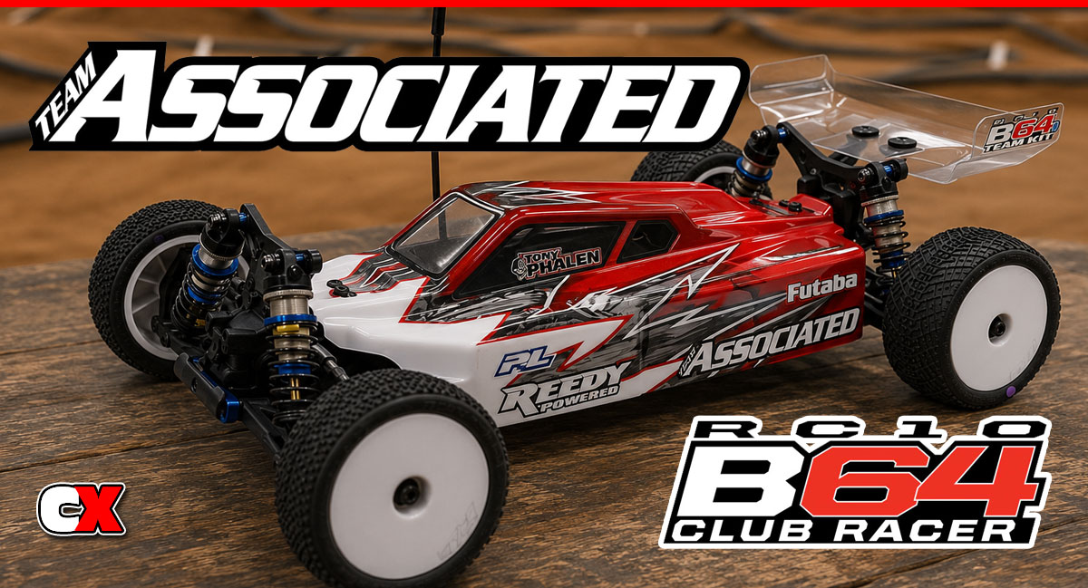
When the news came out that Team Associated was drumming up a new 4-wheeler, there was quite a stir as to what and how different it might be from the B44 series. I actually loved my B44.3, but everyone that has one of the new cars says it’s a night and day difference – I can’t wait to find out!
However, before we get to the build, let’s take a look at the support equipment that we’ll be using with this car. It’s a good thing to note that, other than the wheels, tires and radio system, the Club Racer comes with all the other electronics in separate boxes in the kit!
Team Associated B64 Club Racer Online Build – Part 1
The Team Associated B64 Club Racer comes equipped with 3 planetary gear diffs; front, middle and center. It also comes with large bottles of diff fluid to fill them; 10K and 200K.
Build Notes:
• The diff fluid can be a bit messy, especially the 200K. It’s extremely thick and difficult to work with; just be prepared with some spare towels on hand to clean up the mess.
• We will be showing the build of one diff – the front one – however, you can build the front AND rear together since they are both exactly the same.
Step 1:
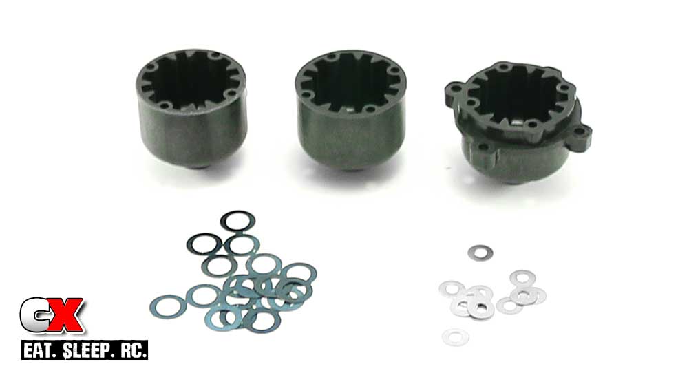
Our first order of business is to separate everything. There are two different gear cases – the two that are the same are for the front and rear diff, the odd one is for the center diff.
You’ll also notice two different sized shims; the black ones are for the input shafts while the silver ones go on the planet gears.
Step 2:
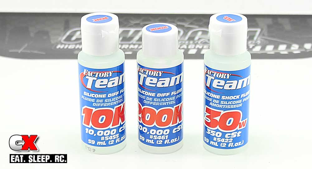
Here’s a look at the fluids included in the kit; 10K for the front and rear diff, 200K for the center diff and 30W for the shocks. Happy to see AE including their normal packaged fluids for future rebuilds.
Step 3:
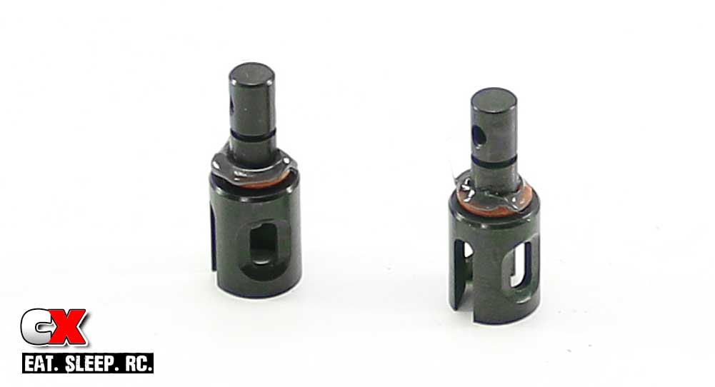
Alright, the first step is to locate the outdrives and slide a red o-ring over them as shown. Slab a liberal amount of grease onto the o-ring to protect it and help keep the seal when installed.
Step 4:
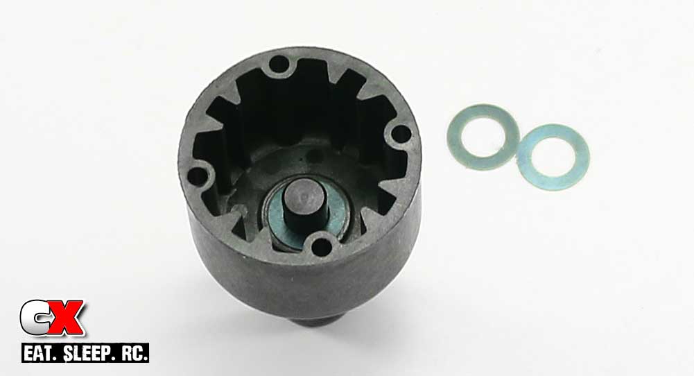
Slide one of the outdrives into the diff case. Drop three (3) black shims down over the outdrive as shown.
Step 5:
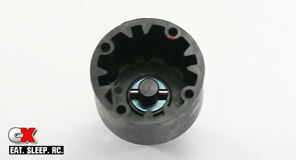
Slide the cross pin through the hole in the outdrive and center it. You may need to press the black shims down a bit to get the pin to slide through.
Step 6:
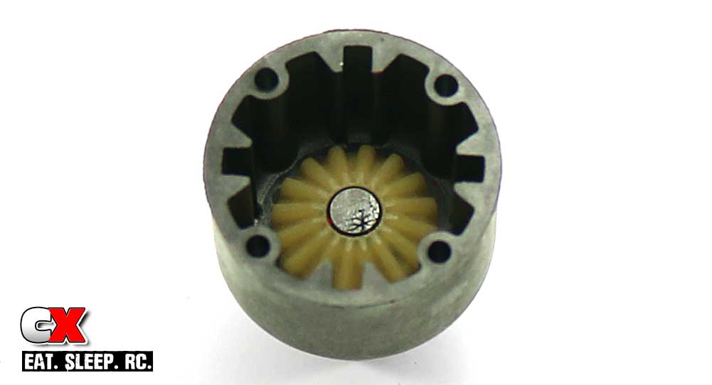
Grab one of larger sun gears and drop it into the case, keying the back of it to the cross pin. I like to use a little bit of black grease on the back side of the gear to keep it from becoming dislodged during handling.
Step 7:
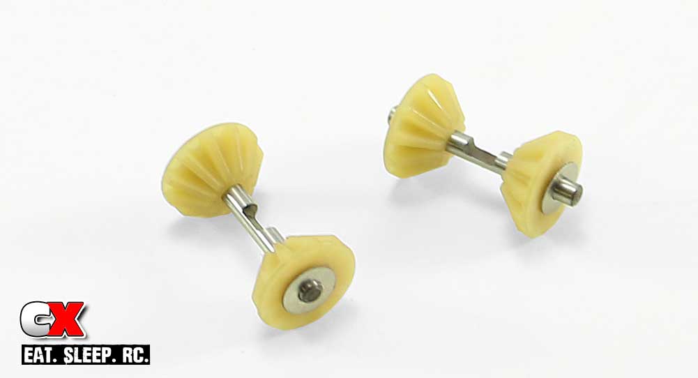
Assemble a pair of the smaller sun gears. Note the silver shims; ONE should be on the backside of each gear.
Step 8:
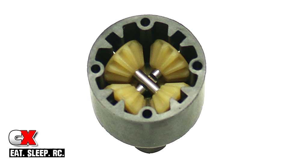
Slide one smaller sun gear assembly into the diff case, making sure the notch in the cross pin is facing up. Now slide the other smaller sun gear assembly into the diff case, making sure the notch in the cross pin is facing down. The two notches should mate up to each other.
Step 9:
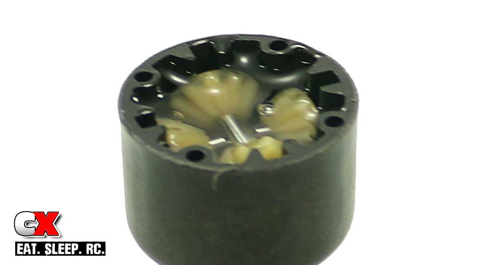
Fill your diff with 10K fluid until it’s to the top of the sun gears. Let it settle a few moments as it seeps down into the crevices and refill if necessary.
Step 10:
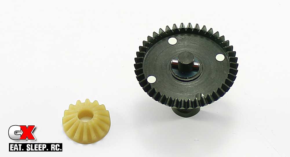
Moving to the other side of the diff, slide the other outdrive into the diff gear followed by 3 shims and the cross pin. Slide the larger sun gear into place, keying it to the cross pin.
Step 11:
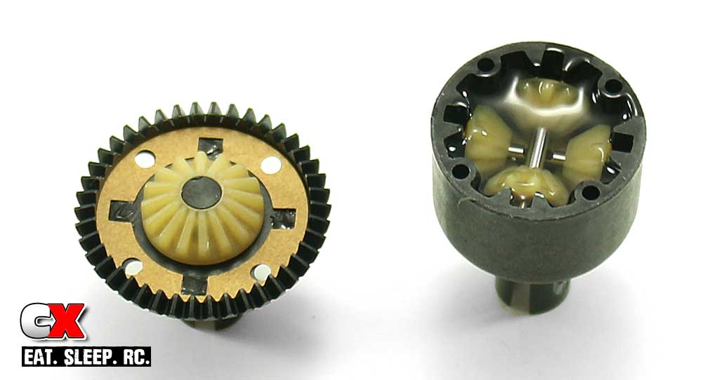
Take one of the diff gaskets and carefully drop it into place as shown. I like to add a very small drop of black grease to keep it located.
Step 12:
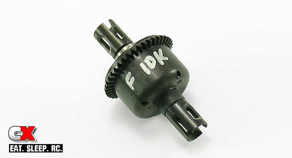
Mate the two halves together, making sure the screw holes line up and secure with the 2.5x8mm screws.
For later reference, I like to write on the outside of the diff the fluid weight. If you’ve built both the front and rear diffs together, add a (F) or (R) just in case you decide to tune the fluid at a later time.
Step 13:
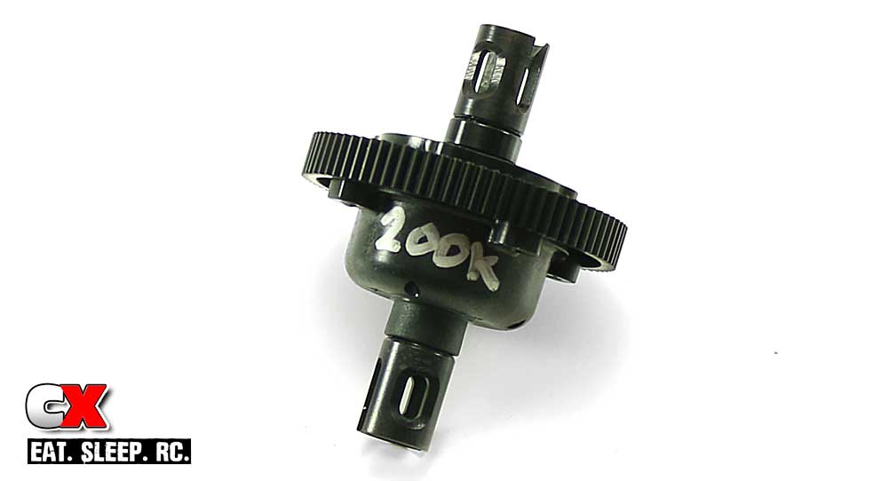
Following the same steps, build the center differential. The only added suggestion I have is to add some of the 200K to the diff prior to installing the pair of planet gear assemblies. Since it’s so thick, it takes a REAL long time seep down into the gears. Applying some early will cut down the wait time.
Now that you’re done with the diffs, take a few moments to clean off any excess fluid from the outside. Set them aside and let’s move on to Part 2 – the Chassis.
Team Associated B64 Club Racer Online Build – Part 2
The next couple of steps have us prep the chassis on the Team Associated B64 Club Racer.
Build Notes:
• Blue threadlocking compound is suggested on quite a few steps from here on out. Have some available to avoid any screws falling out while running your B64 Club Racer.
Step 1:
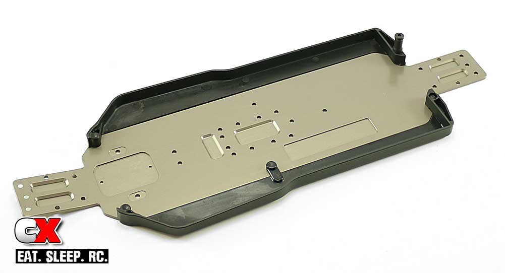
Attach the side rails to the aluminum chassis and add the battery post to the right rear as shown.
Step 2:
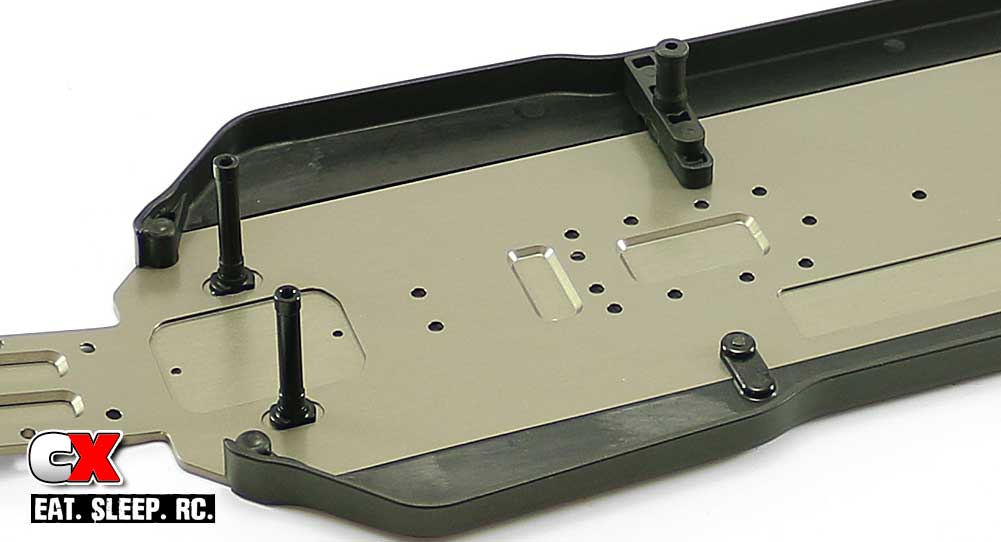
Attach the pair of aluminum servo posts and the battery strap mount. A dab of threadlocker on the screws going into the aluminum posts is recommended.
Step 3:
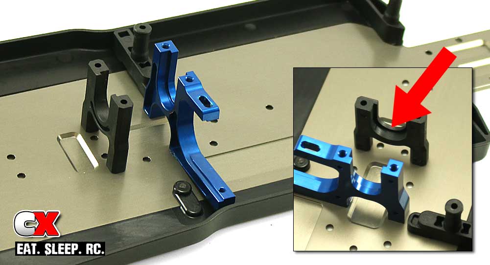
Attach the aluminum and plastic center bulkhead pieces. Blue threadlocker is suggested into the aluminum part.
Note the red arrow; this shows the orientation of the notch on the plastic bulkhead. It should be facing the aluminum mount.
Step 4:
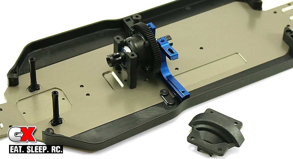
Slide a 10×15 bearing on to each side of the center diff and drop it into place (note its direction). Give it a spin to make sure there is no binding, then attach the center bulkhead cap. Blue threadlocker is suggested here as well.
That was a few easy steps for prep – let’s move on to the steering.
Team Associated B64 Club Racer Online Build – Part 3
The Team Associated B64 Club Racer uses a ball-bearing equipped dual bellcrank steering system. It’s super smooth and very precise, however it doesn’t come with a servo saver. This is fine, however, as the Reedy 0712MG uses a full metal-gear geartrain and shouldn’t need one.
Build Notes:
• As we mentioned earlier, a servo saver is not included with this kit. If you decide you want one (for whatever reason), you’ll need to grab a servo-mounted servo saver. Kimbrough Racing Products makes all kinds of servo-mounted savers – give them a look.
Step 1:
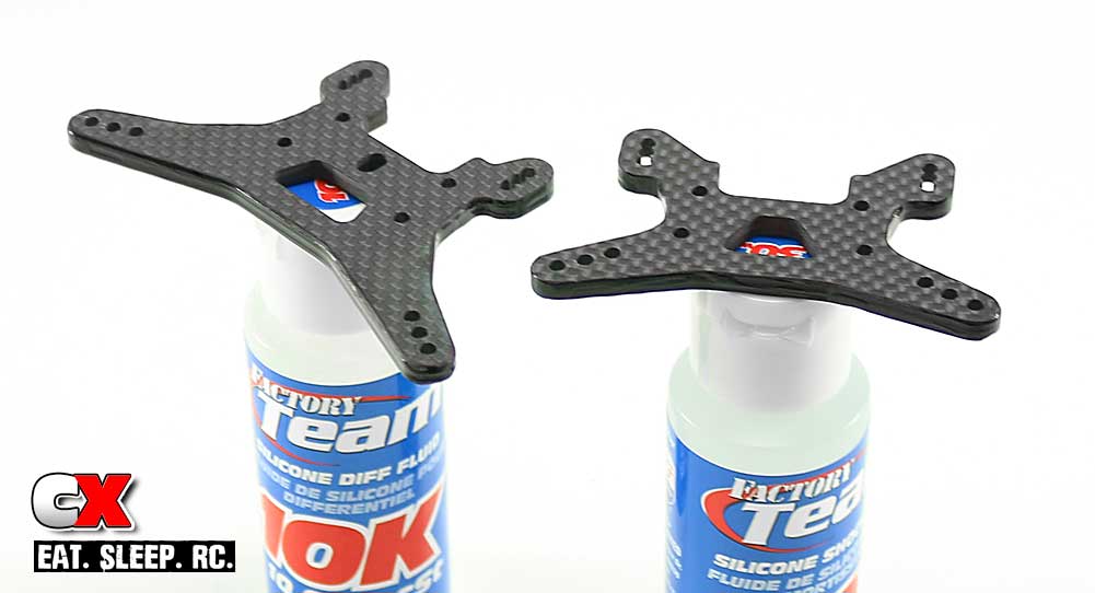
At the beginning of the next step (Part 4 – Front Bulkhead), we’ll be assembling the front shock tower. However, since both the front and rear towers are accessible now I went ahead and prepped them with glue to help keep them from delaminating during a crash. Click this link for the How To: Prep and Seal Your Carbon Fiber Parts. Doing this now also gives the parts plenty of time to dry before we hit Part 4.
Step 2:
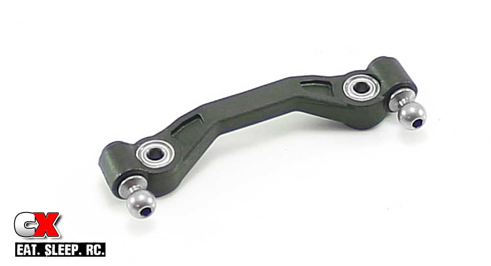
Assemble the steering rack as shown with the ballends and bearings (two bearings per side – don’t forget the 1mm shim in between them). Pay close attention to the orientation of the rack itself.
Step 3:
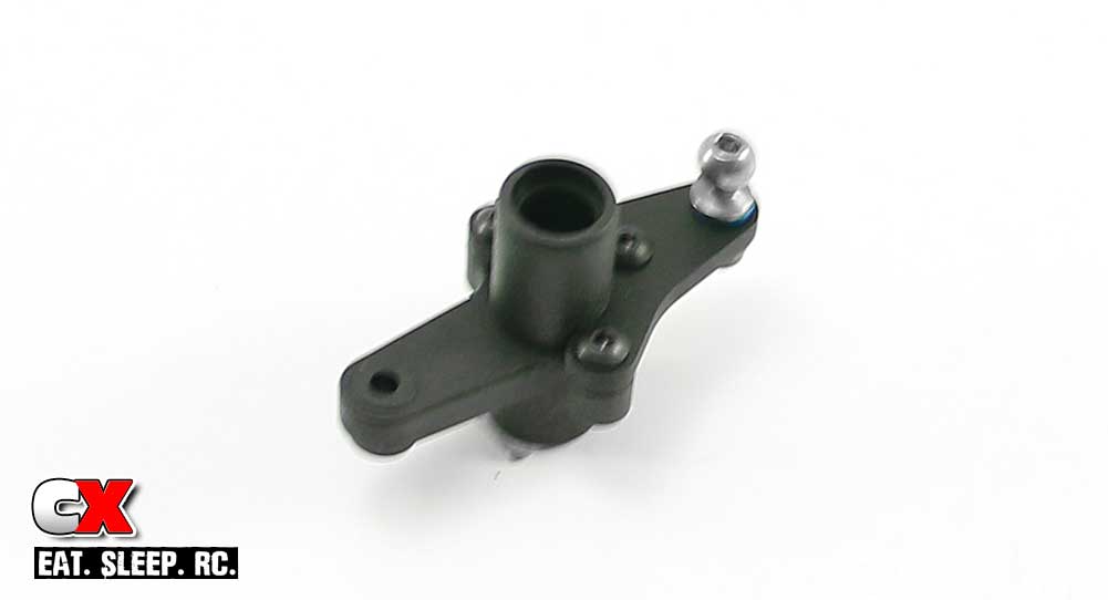
Assemble the left bellcrank. Note the orientation of the parts. Sorry for the slightly blurry picture.
Step 4:
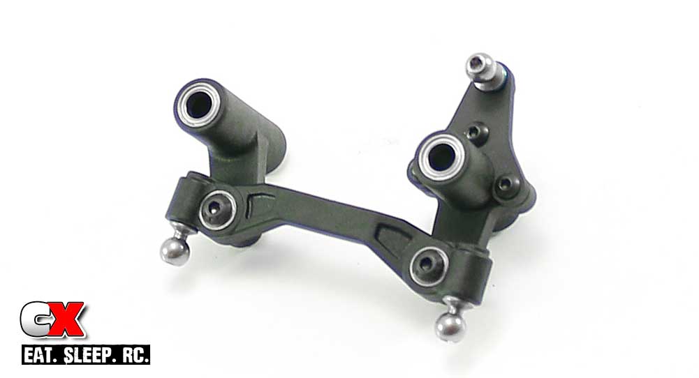
Attach the steering rack to both bellcranks. Do NOT overtighten the 3x14mm screws; make them tight enough to eliminate wobble but loose enough that the bellcranks swing freely.
Add the 5×8 bearings to the top and bottom of the bellcranks as well.
Step 5:
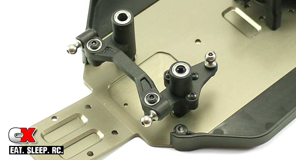
The final step is to slide the steering assembly over the posts.
Before moving on, double check the steering to make sure it swings freely. Great job – time to move on to Part 4.
Team Associated B64 Club Racer Online Build – Part 4
The front gearbox on the Team Associated B64 Club Racer seems pretty stout. Huge bearings, thick plastic and 4mm thick graphite shock towers are all standard equipment.
Build Notes:
• While certainly secure, the input shaft retainer ring is a bit of a bitch to get installed. I found the easiest way to handle this is to lock the hook in the groove of the input shaft and firmly press the ring in place in a circular motion. Trust me, you’ll probably want to throw this part a few times before you figure it out.
• Extra outdrive shims are included to help space your diff to tighten or loosen the gear mesh. I installed 3 shims on each side which made it a little tight, but I figured after a few runs it would probably loosen up a tad. Your experience may vary.
Step 1:
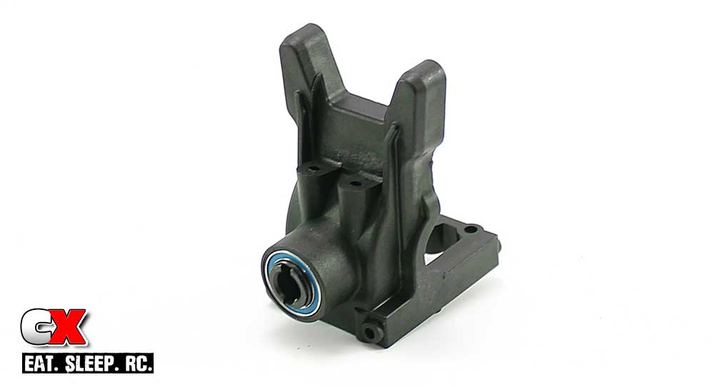
Start off Part 4 by pressing a 10×15 bearing into each side of the gearbox. Slide the input shaft through the bearings (from the inside) and secure it with the input shaft retainer. Enjoy that struggle.
Step 2:
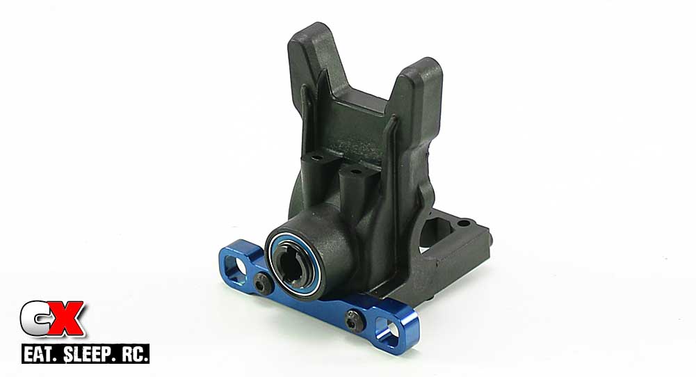
Attach the aluminum B arm mount to the gearbox.
I pressed the 1° Up pills into the gearbox but found that they kept falling out. I left them out and inserted them back in later in the build. You can follow that example or keep re-installing them every few seconds.
Step 3:
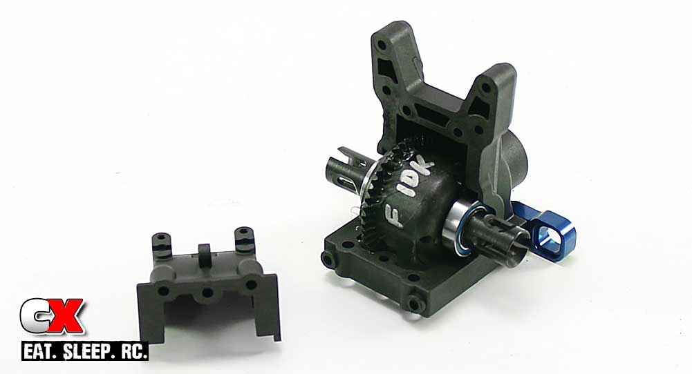
Slide the shims onto the diff (remember, mine felt good with 3 on each side) followed by a 10×15 bearing. Before installing, apply some black grease to the input shaft.
Once you’ve got the diff installed, secure it with the gearbox cap and two 3x10mm screws.
Step 4:
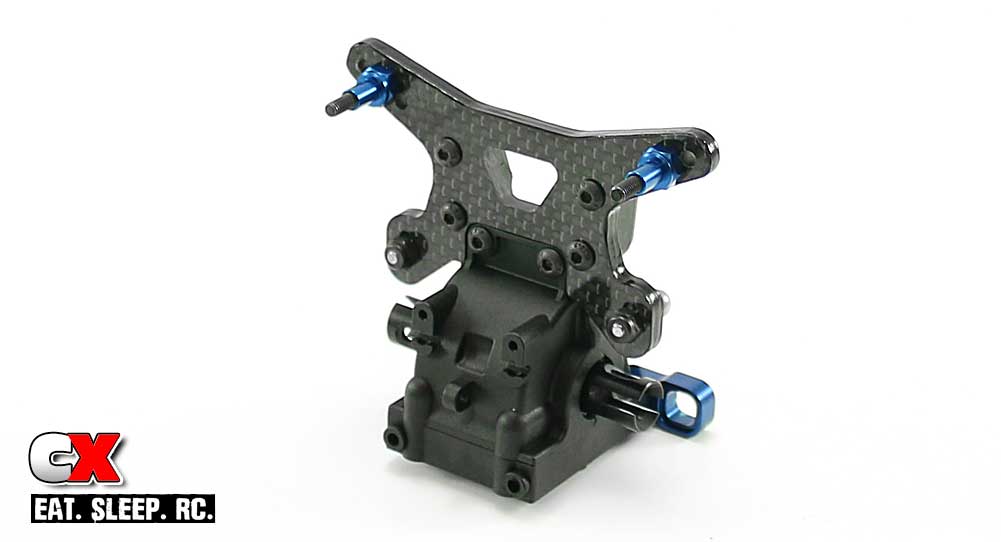
Assemble your CA-prepped front shock tower and attach it to the front gearbox as shown. A dab of blue threadlocker on the shock standoffs is suggested.
Step 5:
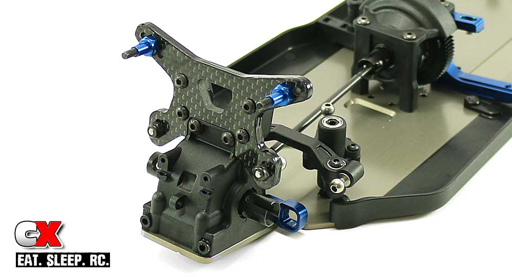
Fit the front dogbone drive into the input shaft on the gearbox. You’ll need to insert it at a pretty severe angle to get it past the retaining clip.
Feed the dogbone under the steering rack and insert it into the center differential. Drop the front gearbox onto the chassis and secure with the 3x10mm and 3x16mm screws. A little black grease on these screws will help them thread into the gearbox a little easier.
Step 6:
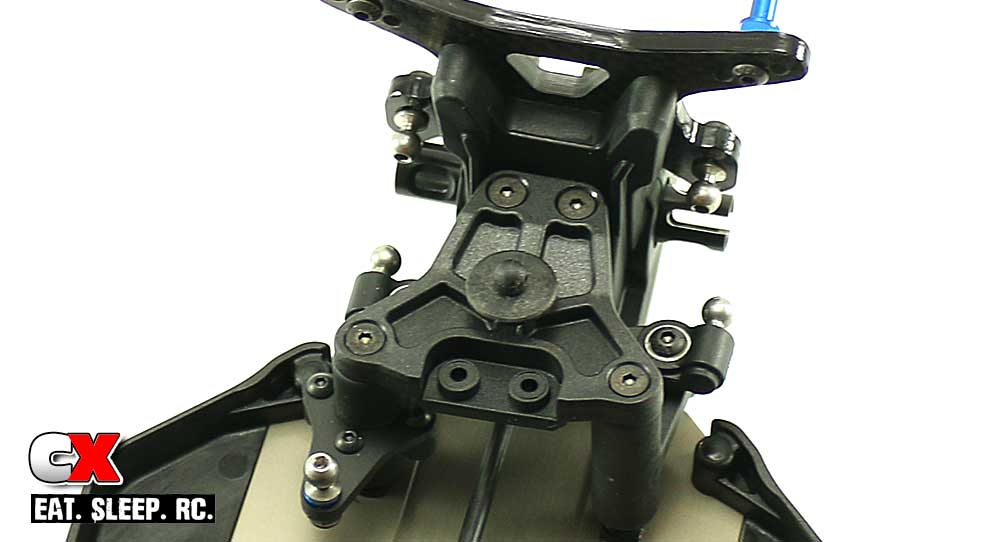
Attach the front body post to the top plate and set that assembly in place to connect the front gearbox and steering system. A light drop of blue threadlocker is suggesed on the screws feeding into the aluminum steering posts.
There ya have it – the front gearbox installed and ready to go. Next up is the front suspension!
Team Associated B64 Club Racer Online Build – Part 5
The Team Associated B64 front suspension has been given a huge facelift over the previous 4-series buggy, using thick suspension arms, aluminum caster blocks and large ball ends to heighten durability.
Build Notes:
• None for this step.
Step 1:
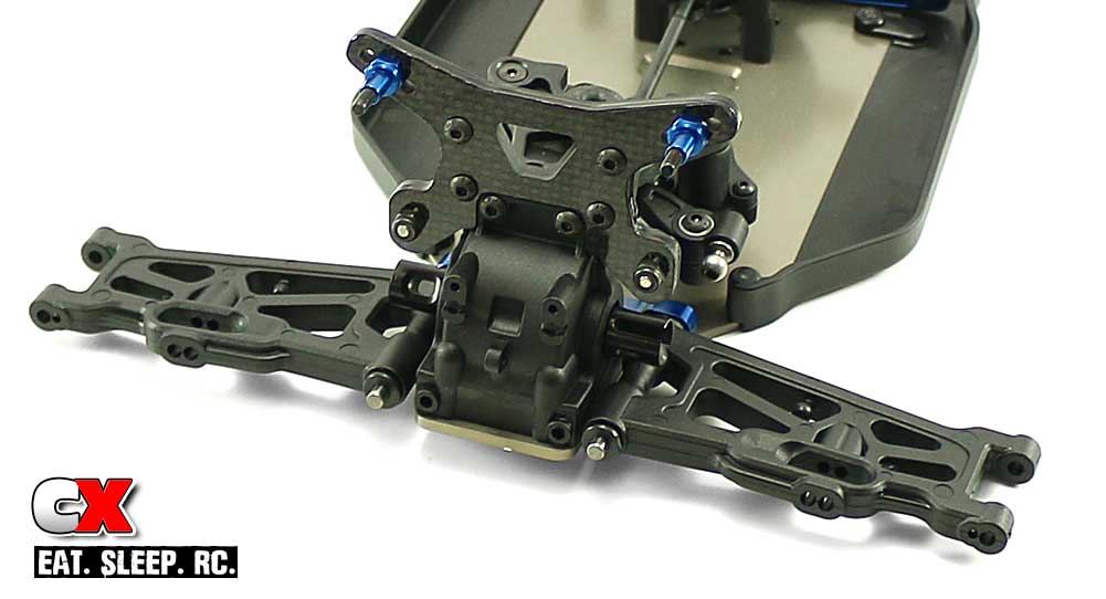
The first thing we need to do is install the pills into the B arm mount from Part 4. If you remember, their fit is pretty loose (at least mine were) and they kept falling out, so I just left them out.
After you install the pills (make sure they are inserted correctly – 1° Up), slide the hinge pins in place followed by the front suspension arms and 1mm shims.
Step 2:
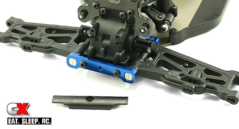
Install the 1° Down pills into the A arm mount and slide it into place, capturing it with the two 3x12mm screws. Cap that off with the plastic front bumper.
Step 3:
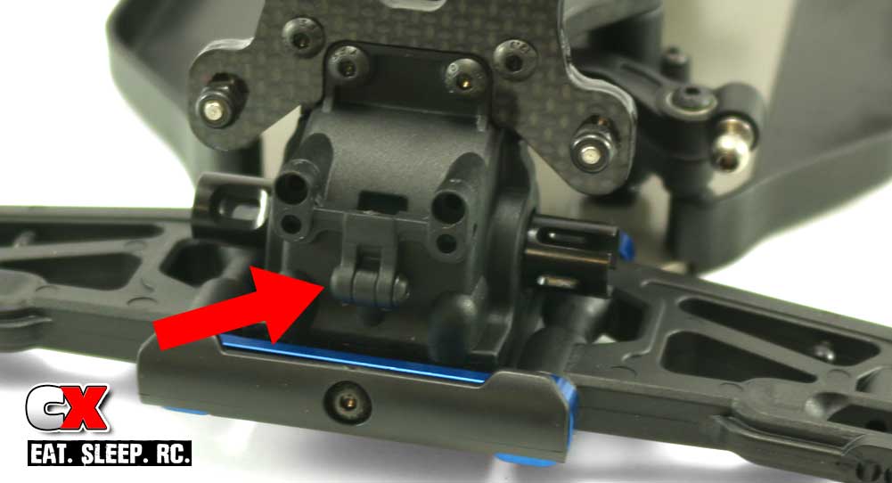
The B64 comes with a front anti-roll bar mount, but the instructions don’t show it being attached since the car doesn’t come with a front anti-roll bar. Since it’s in the box and, well, I don’t want to have to keep track of it, I went ahead and installed it now.
Step 4:
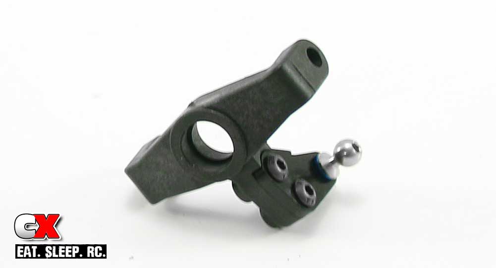
Assemble the left and right steering blocks – the left one is shown here.
Step 5:
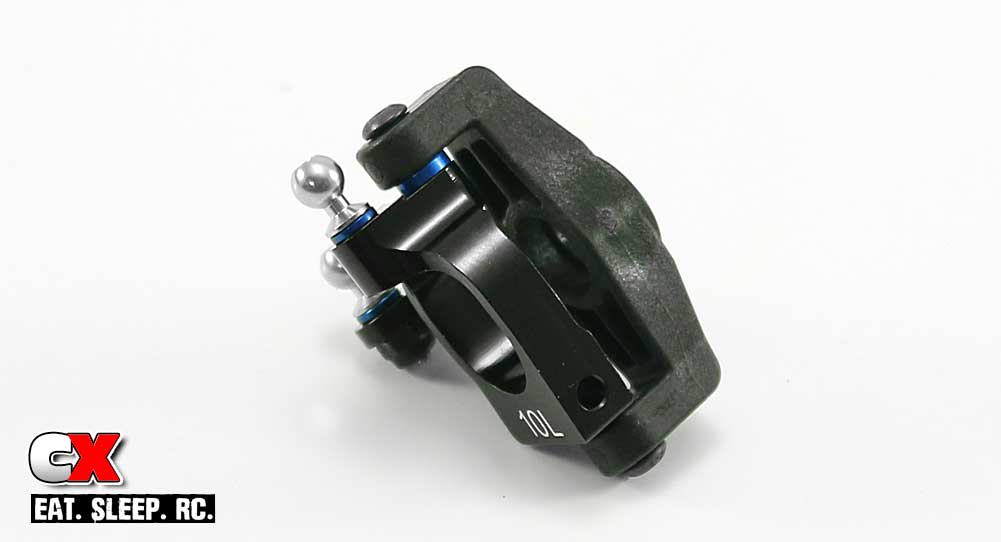
Install the 6mm ballstud and 1mm shim into the aluminum caster block.
Insert the +1 bushing into the top of the steering block assembly, the +2 into the bottom. Now mate the steering block to the aluminum caster block and use the two 3x12mm screws to keep it all together. A dab of blue threadlocker is recommended here on these two screws.
Step 6:
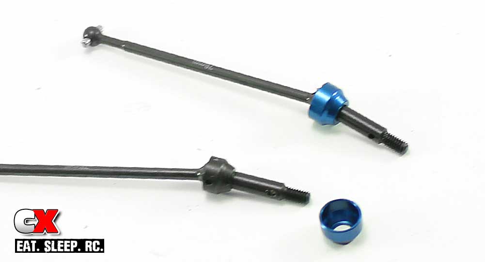
Assemble the pair of front CVA drives. Use a liberal amount of black grease on the ‘ball’ to keep things well lubricated.
These CVAs don’t use a set screw to keep the cross pin in place – that’s what the blue retainer is for.
Step 7:
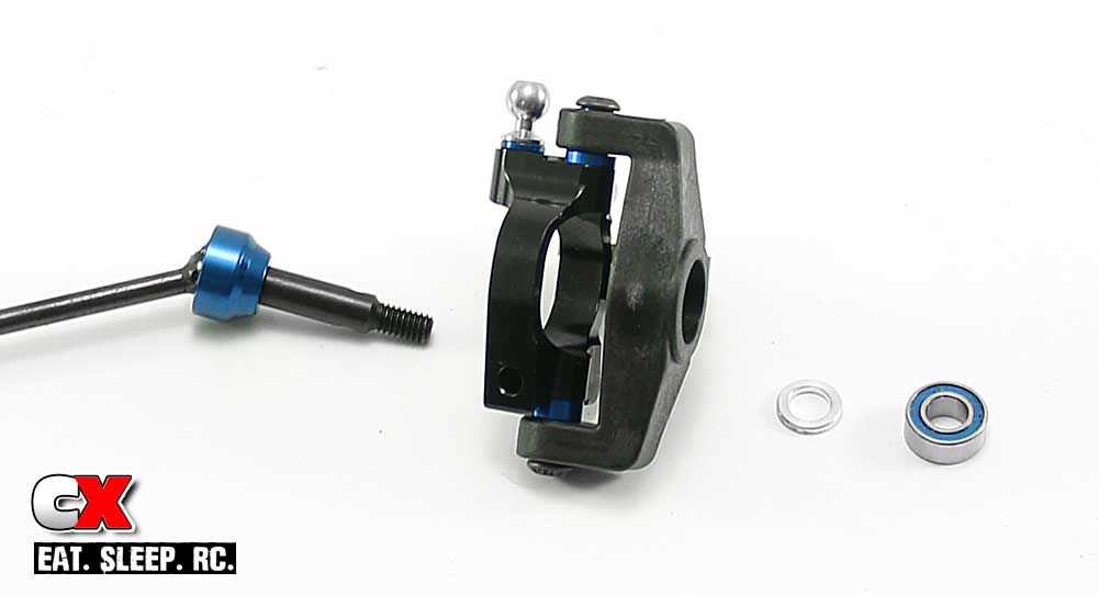
Press the 5×10 bearings into the steering block – don’t forget the crush tube in between them.
Slide the CVA assembly through the steering block…
Step 8:
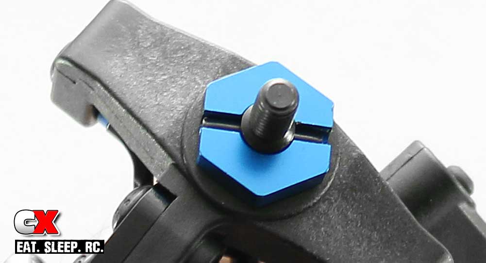
…followed by the wheel hex and roll pin.
The roll pins you’ll need are black, not the shiny silver ones. The black ones are in a separate bag than everything else – I scoured the bench and floor thinking I dropped these – until I looked in the box and found them.
Step 9:
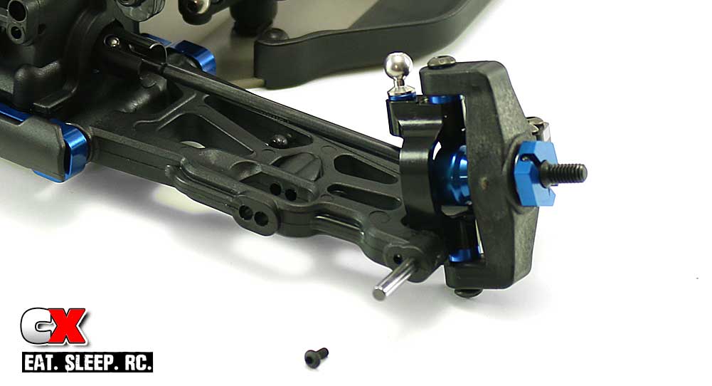
Slide the steering assembly into place and slip the hinge pin through to capture it. The 2x4mm screw is then used to capture the hinge pin.
Nice job! If you haven’t done so yet, complete the other side and then we’re ready to move on.
Team Associated B64 Club Racer Online Build – Part 6
You’ll be happy to hear that you won’t need to purchase electronics for the Team Associated B64 Club Racer. For steering duties, the A-Team has included a Reedy 0712MG servo. It features a full metal geartrain, digital operation and some decent specs; a speed of .12 and a torque rating of 246oz!
Build Notes:
• Before attaching the servo, it is suggested that you connect all the electronics up and test them. This is also helpful in centering the servo when attaching the servo horn.
• Depending on where you end up mounting your receiver, it is suggested that your route your servo wire to the left side of the chassis in Step 3. I wanted mine to feed through the triangles in the aluminum chassis braces (to keep it away from the drive bone) but, because of the tight fit, couldn’t make it happen once everything was installed. Just a heads up.
Step 1:
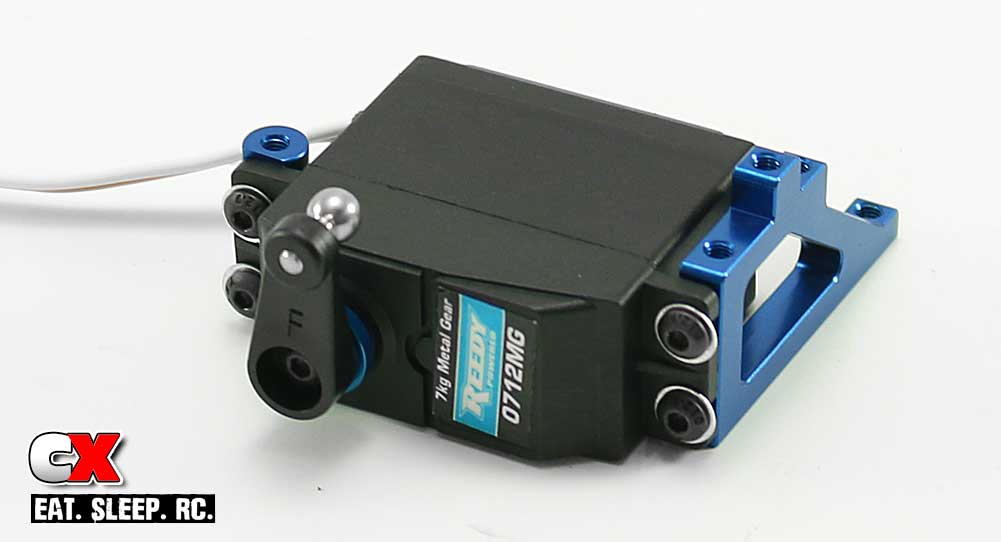
To start off this step, build the 25T ‘F’ horn (or Futaba horn) as shown; servo horn ring and 4mm ballstud. Attach that to the servo.
Attach the left and right servo mounts, using a dab of blue threadlocker on the screws to keep them secure. Leave them a little loose for the moment
Step 2:
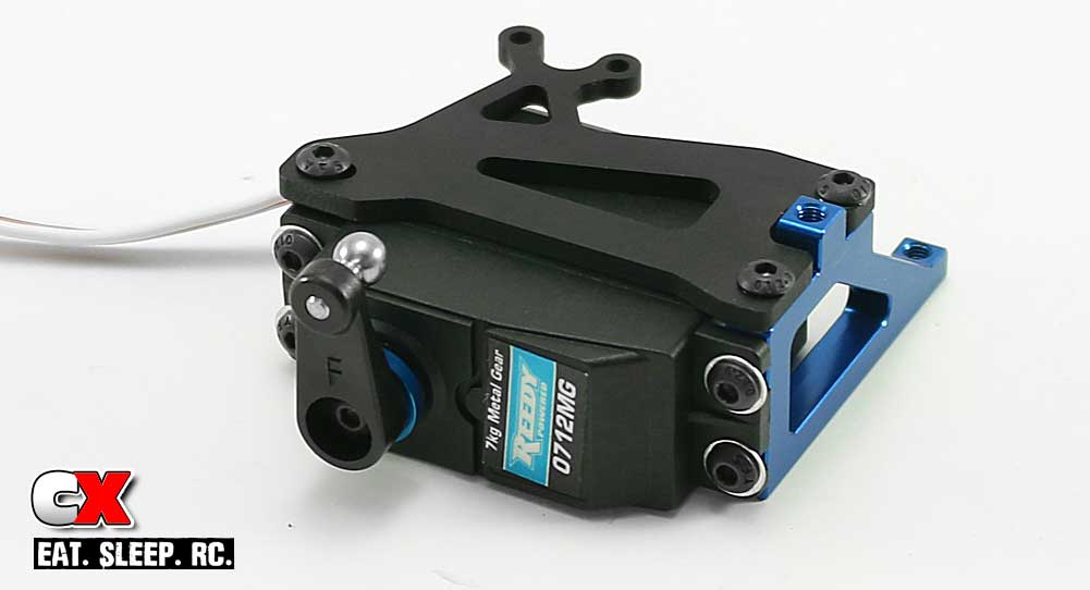
Attach the floating servo brace, using blue theadlocker on these screws as well. Tighten them down.
You can now tighten down the 4 screws from Step 1.
Step 3:
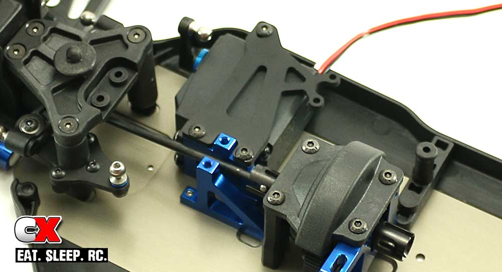
Screw the servo in place on the chassis. You can also attach the second chassis mount brace at this time.
Step 4:
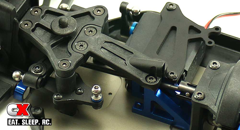
The final step is to attach the upper front chassis brace.
Servo install complete! Set the chassis assembly aside and let’s get cookin’ on the rear gearbox!
Team Associated B64 Club Racer Online Build – Part 7
The rear bulkhead build on the Team Associated B64 is very similar to the front; there are only a few minor differences that separate them.
Build Notes:
• You’ll get another chance to deal with the finiky input shaft retainer ring. I hope you remember how you installed the first one.
• Extra outdrive shims are included to help space your diff to tighten or loosen the gear mesh. I installed 3 shims on each side which made it a little tight, but I figured after a few runs it would probably loosen up a tad. Your experience may vary.
Step 1:
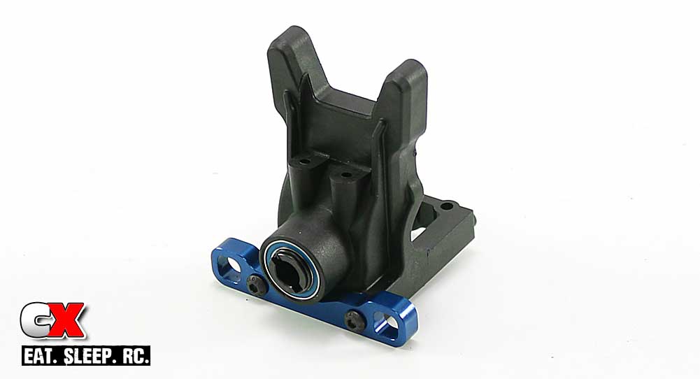
Use the same steps as you did to assemble the front gearbox; bearings, input shaft and retainer ring. The only difference is the C arm mount installation.
Here’s where I found a slight issue; the manual shows a 0° Down pill – I didn’t see any 0° pills. In the rest of the diagrams it shows the pill with the center-pip – it also shows that in the setup at the back of the manual. I disregarded the 0° Down pill option and went with the center-pip version.
However, you’ll notice that they are not installed – they kept falling out so I popped them in at a later step.
Step 2:
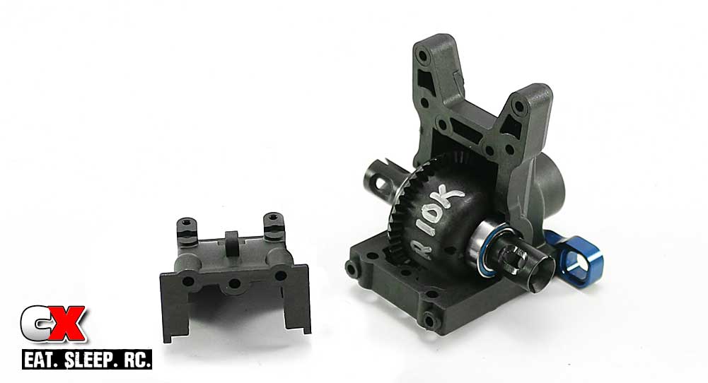
Slide the shims on the diff followed by the 10×15 bearings; I used 3 shims on each side.
Set the rear diff in place and capture it with the gearbox cap and 3x10mm screws.
Step 3:
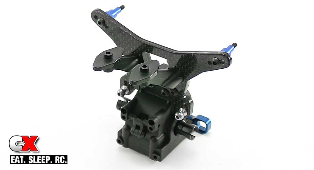
Assemble the rear shock tower, including the wing mounts and body mount, and attach. You can also install the rear anti-roll bar mount.
Step 4:
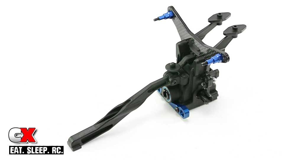
The B64 has the option to use a long or short rear chassis brace. This changes the flex characteristics at the back of the buggy.
To start out, I installed the kit suggested long brace.
Step 5:
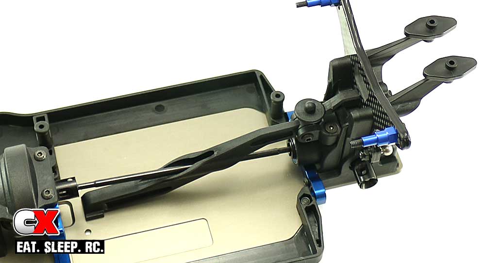
Feed the rear drive bone through the opening in the rear brace and into the input shaft in the gearbox. Place the entire assembly onto the rear of the chassis and secure.
Like the front, it is suggested to use a small amount of black grease on the gearbox screws to help them thread in easier.
At this time, you may just want to give the drivetrain a spin to make sure there is no binding. Other than that, you’re all set to move on!
Team Associated B64 Club Racer Online Build – Part 8
The rear suspension on the Team Associated B64 is the similar to the front but includes an anti-roll bar. The build should be almost identical other than that.
Build Notes:
• As noted in Part 7, there are no 0° Up (or Down) pills – we’ll be substituting those out for the center-pip pills that are included.
Step 1:
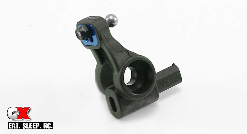
Assemble a pair of rear hubs; note the orientation of the hub link inserts. We’ll also be installing the 1/2-Tab Up inserts into each one.
Step 2:
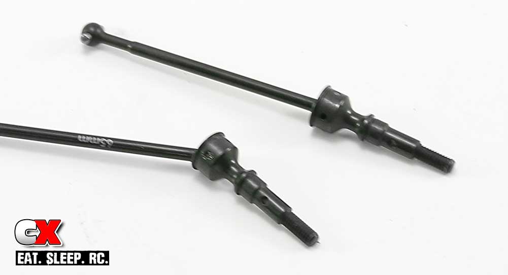
Assemble a pair of rear CVA drive axles, using a liberal amount of black grease on the ‘ball’ to keep things well lubricated during use.
Step 3:
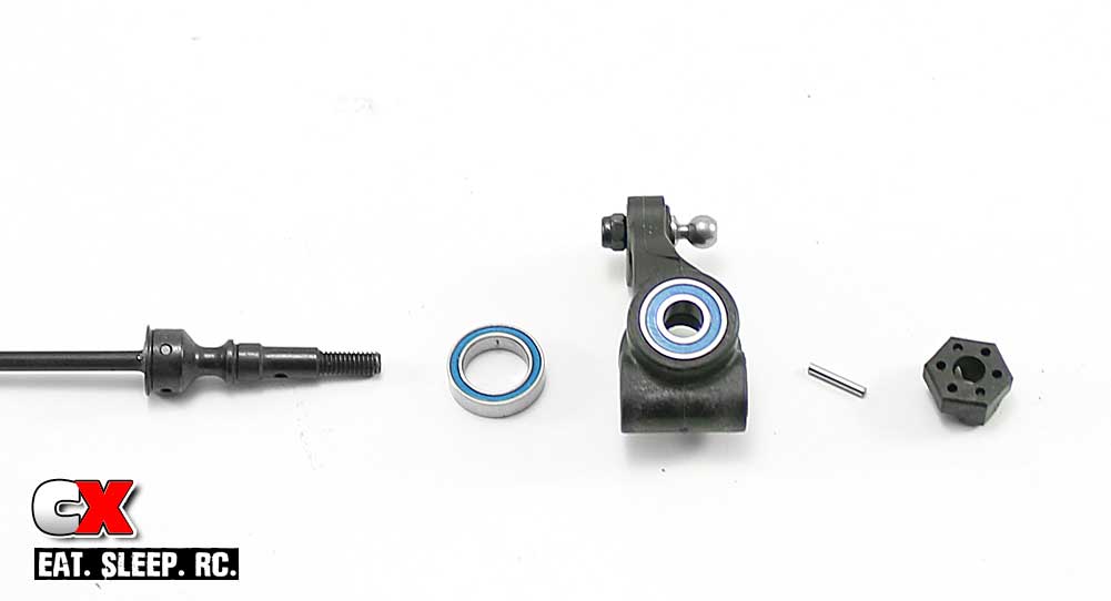
Press the 10×15 and 6×13 bearings into the rear hub, then slide the rear CVA through. Slide the wheel hex pin through the hole in the CVA followed by the wheel hex to hold it in place.
Step 4:
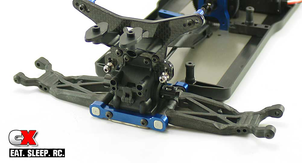
Press the center-pip pills into the C arm mount, then slide the hinge pins into place. Follow that with the 1mm arm shims, rear suspension arms (note their orientation) and D arm mount (also using center-pip pills).
Step 5:
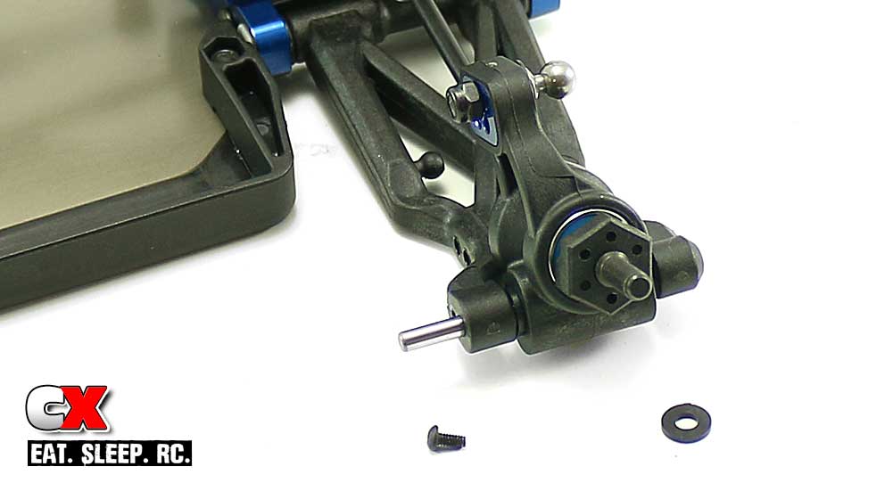
Set the rear rear hubs into place and slide the hinge pin through. Make sure you insert one of the arm mount shims on either side of the hub. Use the 2x4mm screw to secure the hinge pin.
Step 6:
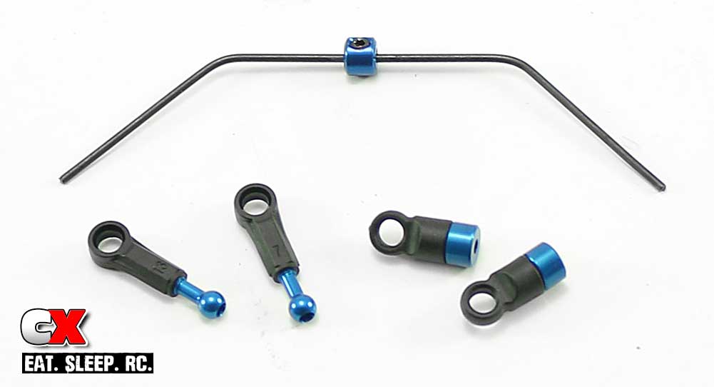
Assemble the anti-roll bar parts as shown. The couplers that feed into the eyelets can be a bit of a pain to insert straight, but take your time and you’ll get it.
Step 7:
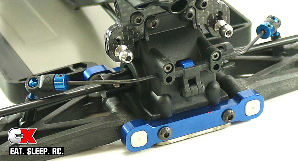
Attach the anti-roll bar. Feed the 3x3mm setscrews in until they hit the anti-roll bar, then back them out a tick. You don’t want them hindering the anti-roll bar movement but you do want them to prevent slop.
Great job – almost done! Only a few more key elements left and you’ll be on the track with your B64 in no time!
Team Associated B64 Club Racer Online Build – Part 9
Team Associated’s B64 comes with shiny, steel turnbuckles. While they’re not titanium, I’m certainly glad they’re not the black steel ones!
Build Notes:
• Threading in turnbuckles can sometimes be a bit of a pain, so I suggest using something to lubricate the threads – in this case, Chapstick. If you use the strawberry flavor your turnbuckles will smell good as well.
• The center of the turnbuckle (the adjustment block) has a notch in it; this notch should be facing the same direction on all your links when they are installed. This makes it easier to discern which direction to turn them for adjustment.
Step 1:
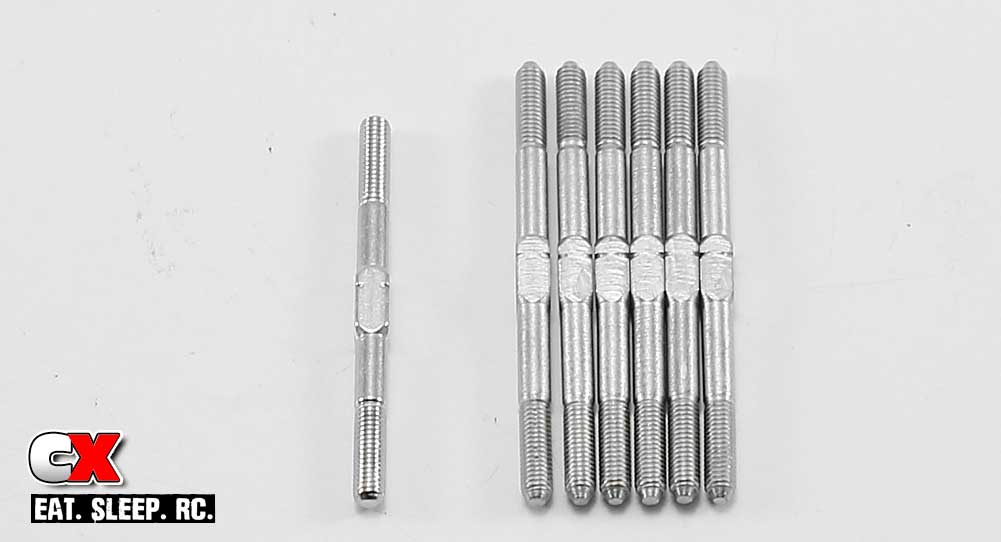
The B64 comes with 2 different lengths of turnbuckles; a short one for the drag link and six others for the camber and steering links.
Step 2:
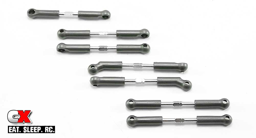
Follow the instructions to build the links, but make sure you keep them separated! Your final product should look like this.
Step 3:
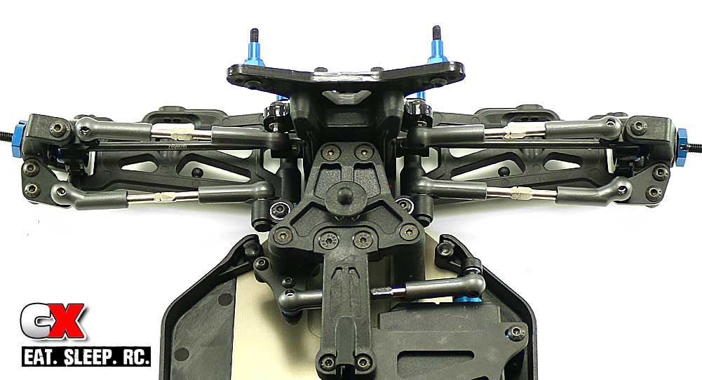
Attach the drag link, steering links and front camber links as shown. Note the adjustment notch is facing the same direction on all the turnbuckles.
Step 4:
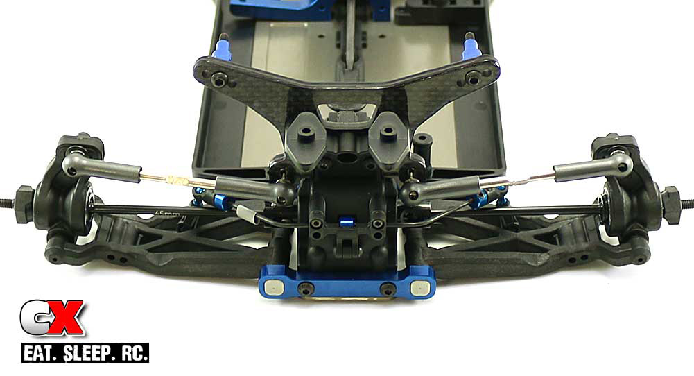
Insert the CVA bone into the diff outdrive and attach the rear camber links. Note the notches are facing the same direction as the ones on the front turnbuckles.
Pretty easy, yes? The lengths supplied by AE in the manual appear to be spot on, but you can make any adjustments during the final prep right before we hit the track.
Team Associated B64 Club Racer Online Build – Part 10
Large, V2 12mm Big Bore threaded aluminum shocks are included with the Team Associated B64 Club Racer. These shocks feature 3mm shafts and super smooth X-rings for excellent rough-terraing handling.
Build Notes:
• Shock building = messy. I suggest a clean environment as well as some rags or towels to wipe up any mishaps you might have during the building process.
• During Step 10, you will have oil oozing out on to the outside of your shocks. If you’re like me, simply wiping it off just won’t do. You can use a spritz of motor cleaner to help remove the oil, leaving you a nice shiny shock!
Step 1:
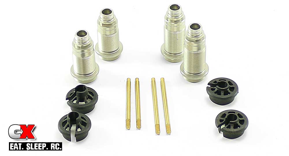
Before I get started, I like to separate all my parts to make the build a little smoother. On the left are the front aluminum bodies, 23mm shafts and 5mm offset spring cups. On the right, rear bodies, 27.5mm shafts and 0mm offset spring cups.
Step 2:
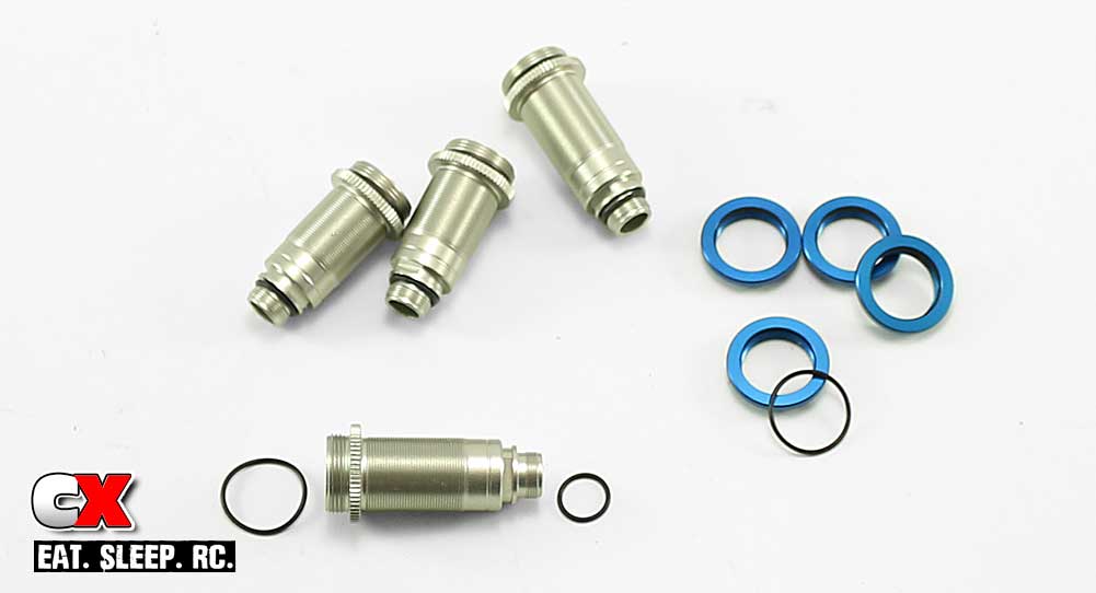
Another thing I like to do in the beginning is seat all of the o-rings. This makes it easier to install them while you fingers (and the o-rings) are free from oils.
Step 3:
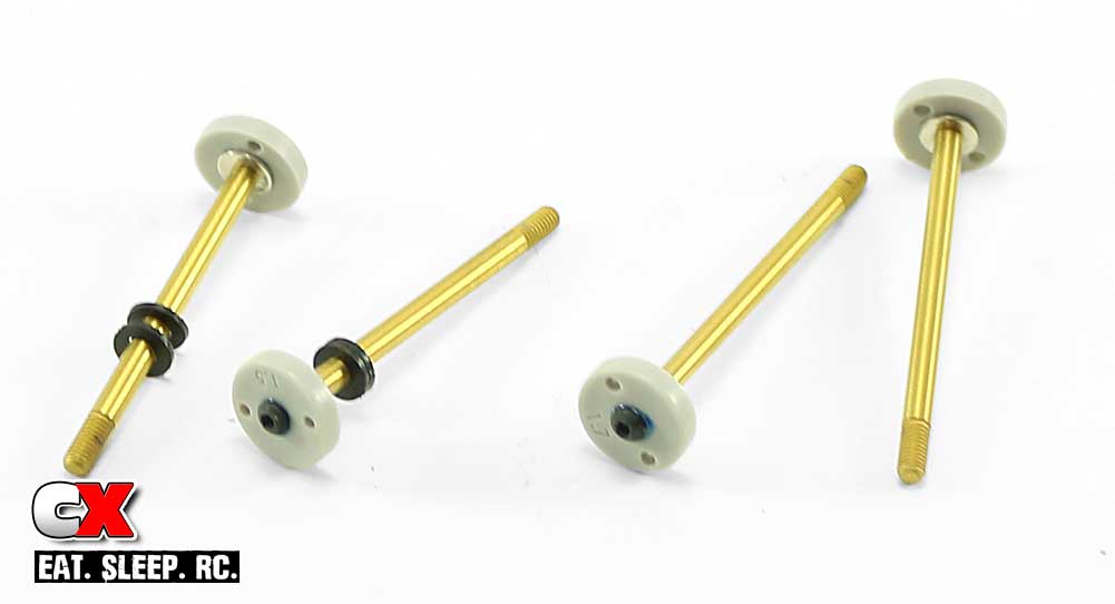
Alright, on to the build. On the left we have the front shock shaft built with 1.5 pistons and two .030 plastic spacers. On the right, the rear shock shafts with 1.7 pistons. A light drop of blue threadlocker is suggested to keep the screws firmly in place.
Step 4:
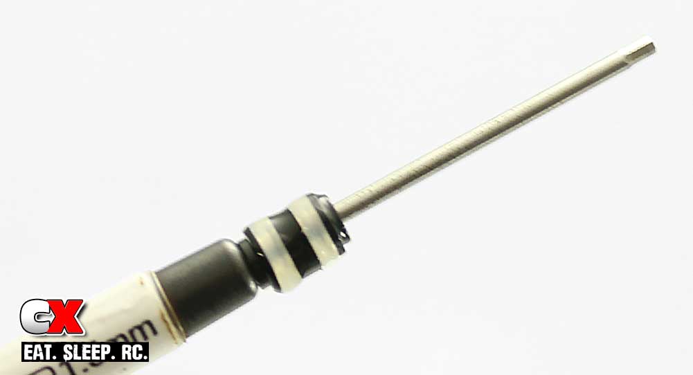
Installing the bottom cartridge parts can be a little messy, so I’ve found an easy way to do it. Slide the parts onto one of your wrenches in the order they are to be installed, coat with a light drop of shock fluid and slide them into the bottom of the shock. Super easy with virtually no mess.
Step 5:
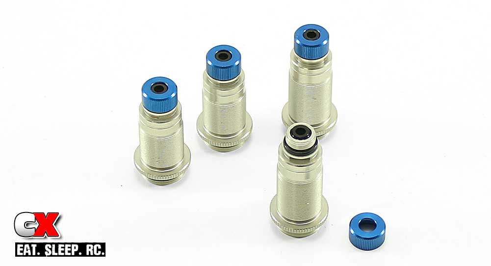
Capture the cartridge parts with the bottom blue shock cap.
Step 6:
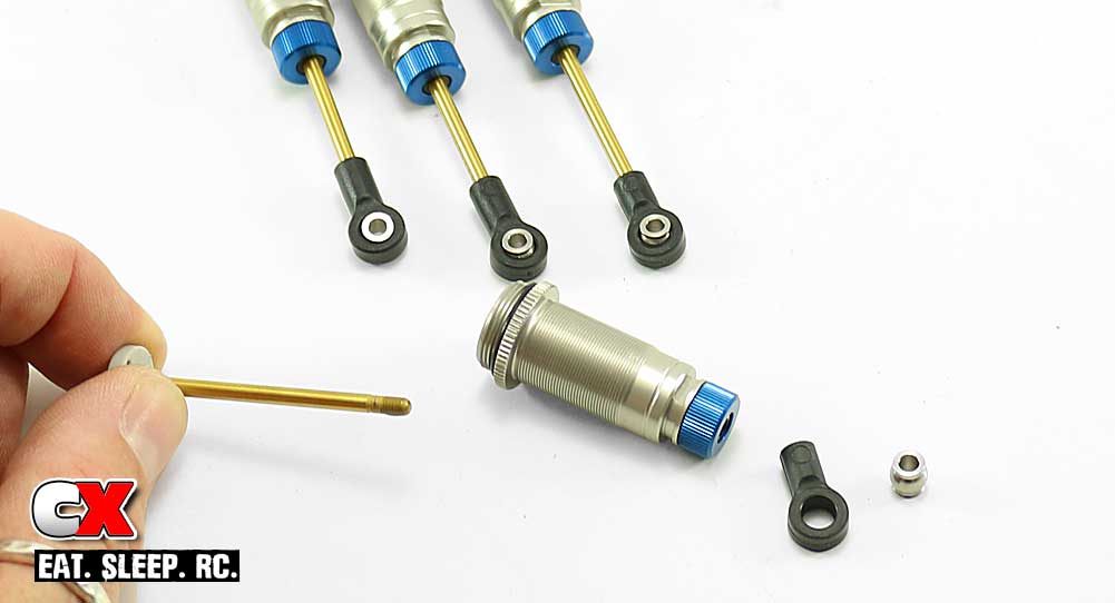
Coat the threads of your shock shafts with a drop of shock fluid and insert them into the shock body. Make sure you insert the 23mm shafts into the short front bodies and the 27.5mm shafts in to the longer rear bodies.
Press a pivot ball into each shock eyelet and screw them onto the shock shaft (kit: front shocks, long eyelet – rear shocks, short eyelet).
Step 7:
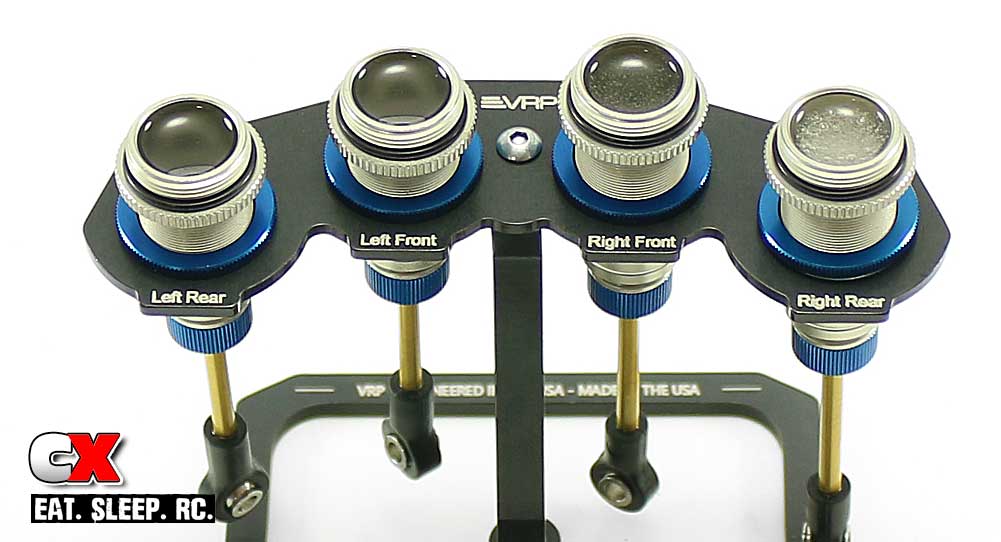
Before filling with oil, I suggest installing the shock collars. Depending on what shock stand you are using, this will help keep them stable in the stand.
Fill each shock with oil, plunging the shaft up and down to help remove any air bubbles. Set them aside in your shock stand and wait a few minutes for the air bubbles to clear.
Step 8:
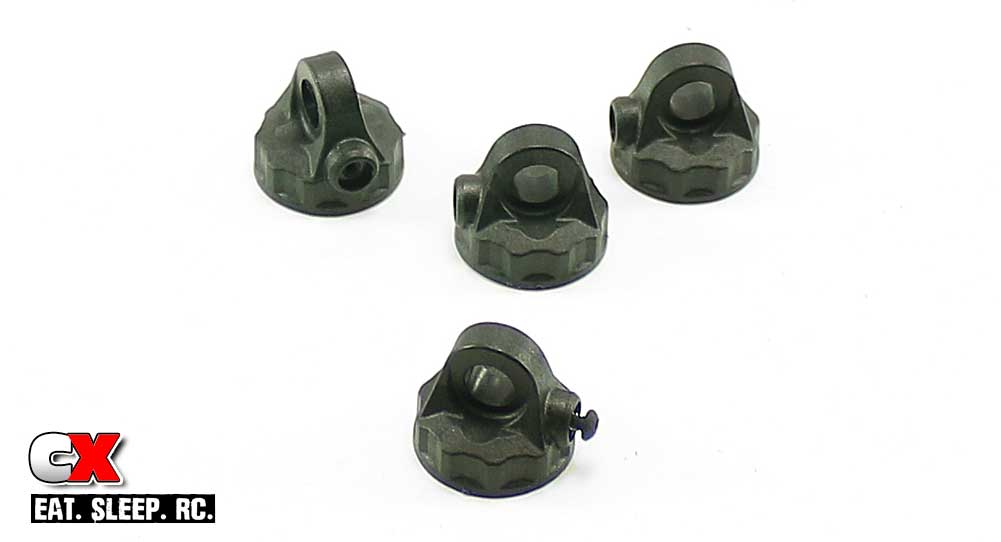
While you’re waiting, go ahead and pre-tap the bleeder holes in the shock caps with the M2x4mm screw.
Step 9:
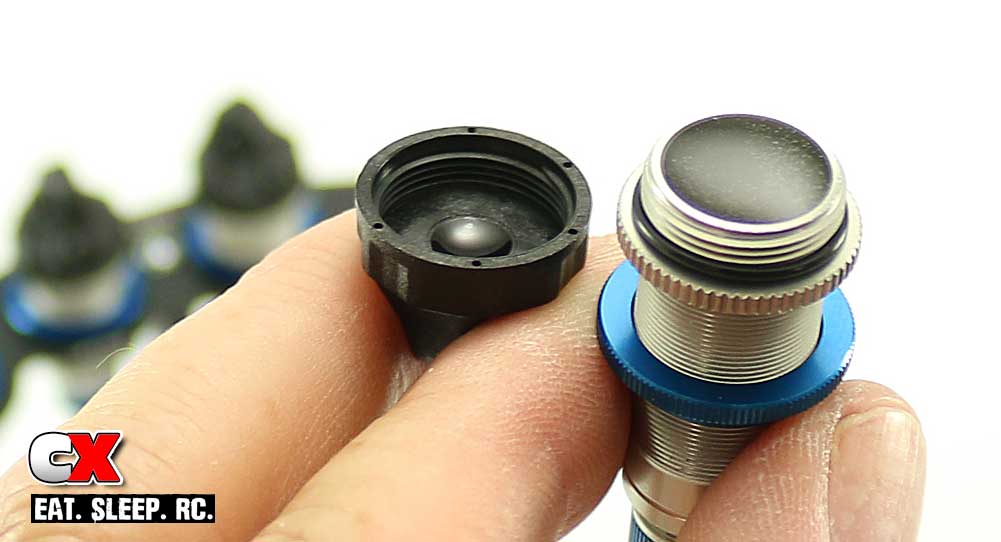
Grab your shock and fill it to the top with oil (so the oil is level with the rim). Put a single drop of oil in the cap as well.
Step 10:
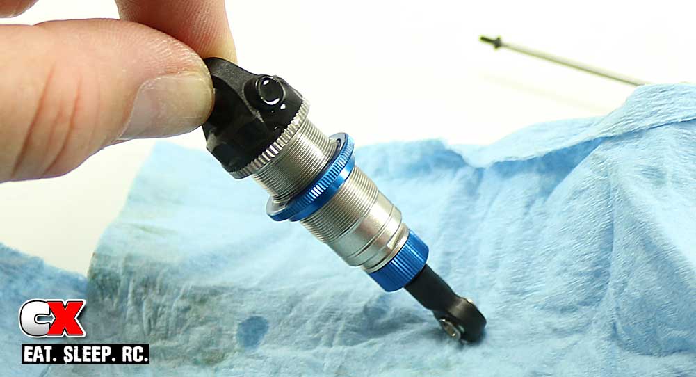
Screw the cap on to the top of the shock. Now, on some sort of rag, slowly compress the shock until it bottoms out. During this time, some oil will flow out of the shock cap – this is normal.
Once fully compressed, insert the M2x4mm screw to seal the hole. Wipe off any extra oil that’s on the outside of the shock.
Step 11:
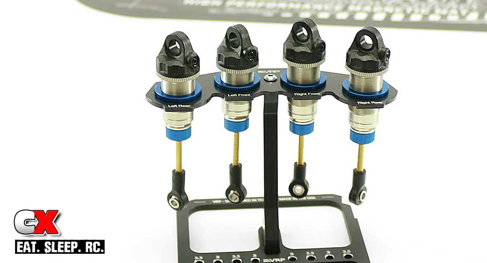
There you have it – four pretty little shocks are filled, sealed and clean!
Step 12:
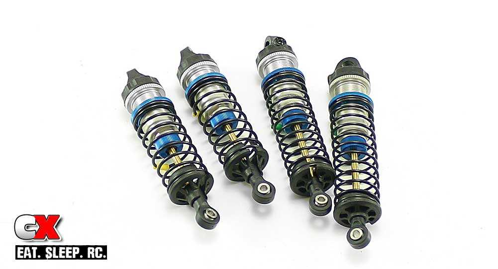
Thread the shock collars up to the manual-specified height (8.25mm for the front, 6mm for the rear) and install the springs and spring cups.
Step 13:
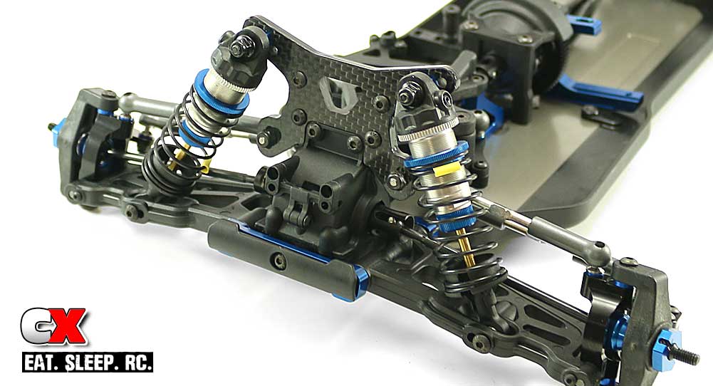
Install the front shocks onto the buggy.
Step 14:
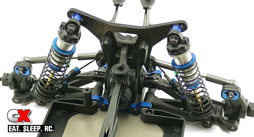
Install the rear shocks onto the buggy.
Other than the tires, the shocks are probably the most crucial setup piece of the puzzle. This step was a little longer than most but we got ‘er done! Great job!
Let’s get to the final steps – the electronics and body/wheels/tires!
Team Associated B64 Club Racer Online Build – Part 11
There is plenty of room on the Team Associated B64 Club Racer chassis for electronics, especially the ones included with the kit. We have the Reedy 600Z ESC, Sonic 13.5T FT (Fixed-Timing) motor and Reedy Zappers 4800mAh shorty LiPo battery – all great components for this car!
Build Notes:
• For this step, you’ll need a soldering iron handy to attach the wires from the ESC to the motor. A few zipties would be handy as well for wrapping up additional wiring.
Step 1:
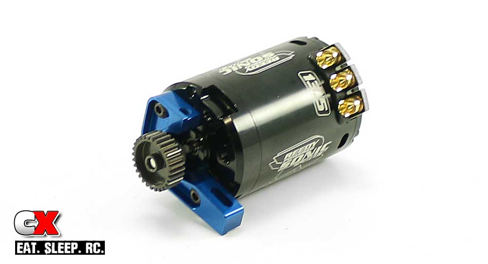
Attach the motor to the blue aluminum mount, then attach the pinion to the motor. Note the orientation of the motor wire connectors – you’ll want them somewhere near this position to make it easy to attach the wires.
Step 2:
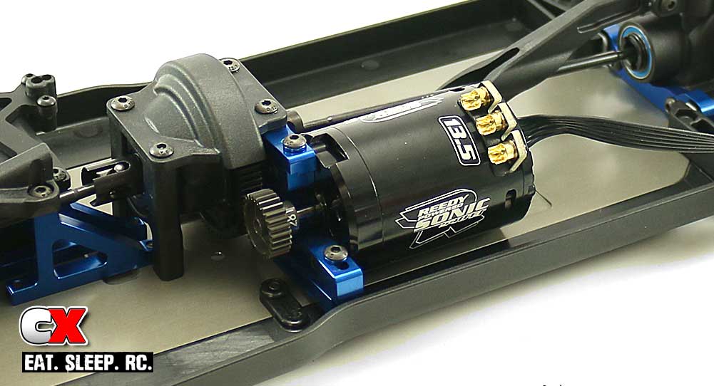
Attach the sensor wire to the back of the motor and slip the assembly into place. Adjust the gear mesh and tighten down the 3x10mm screws.
Step 3:
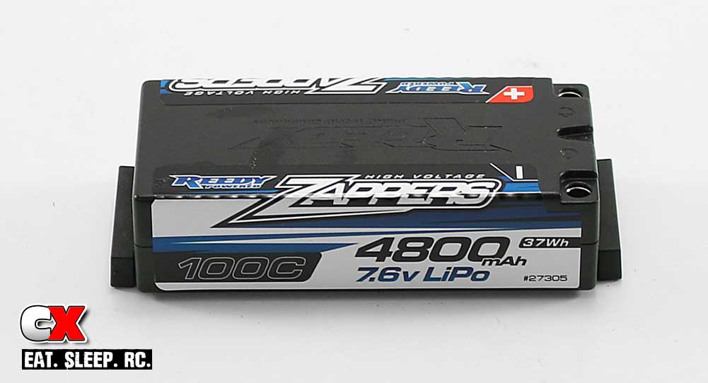
The B64 Club Racer battery mount allows for three different battery positions; front, mid and rear. These positions are configured with 2 small plastic spacers. The picture above shows the battery in mid-position with a spacer on each side.
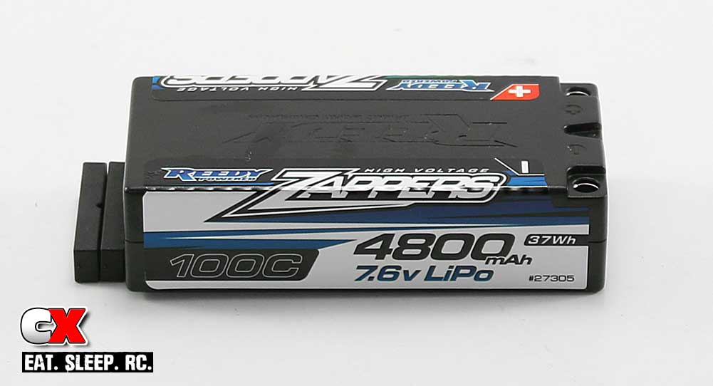
Here is the battery in forward position; both spacers are behind it.
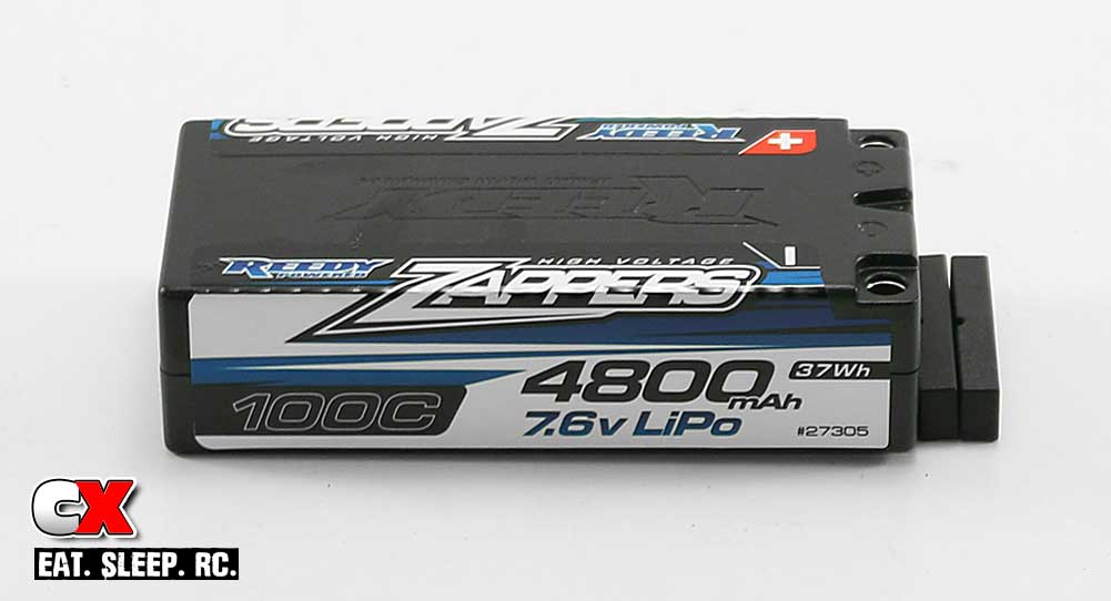
Finally, the battery in the rearmost position; both spacers in front of it.
For this build, we’re going to have the battery in the mid-position.
Step 4:
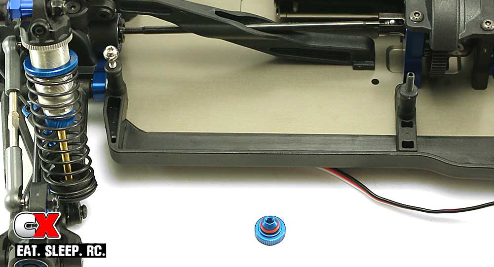
Install the rear battery swayball joint and the 3x10mm set screw. You can also slide the red o-ring over the battery thumbwheel.
Step 5:
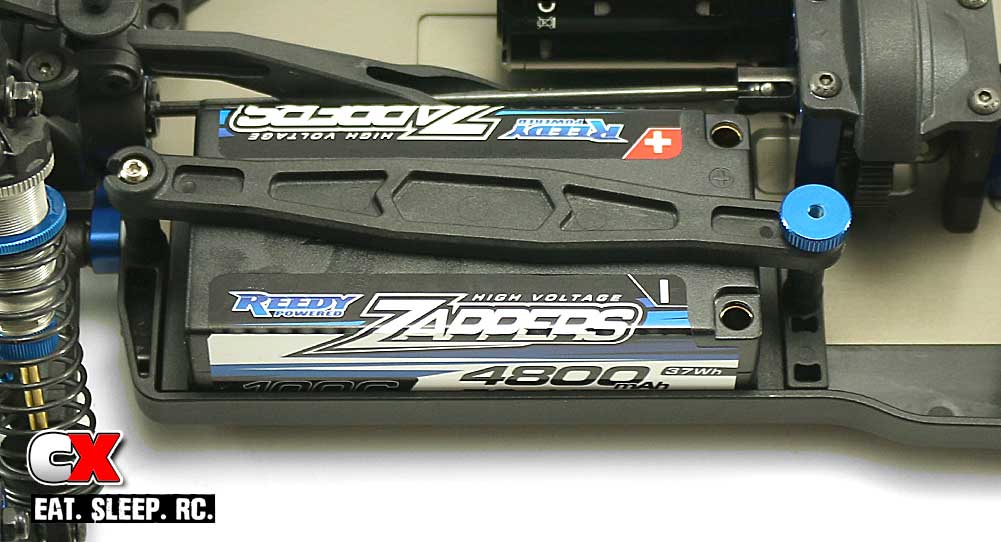
Set the battery and spacers in place and connect the battery strap. Thread the thumbwheel down to hold the strap in place.
Step 6:
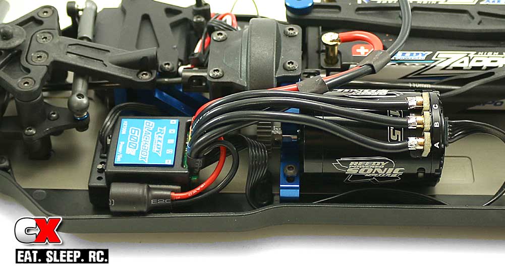
Wire up your electronics (left side).
Step 7:
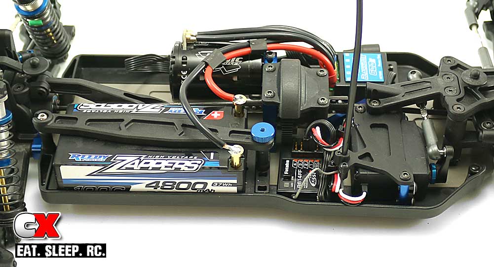
Wire up your electronics (right side).
I would suggest, at this time, turning everything on again and give it a test. If everything is good, you’re all set to move on to the final step of the Team Associated B64 Club Racer build!
Team Associated B64 Club Racer Online Build – Part 12
The Team Associated B64 Club Racer comes with a wing and body, however it doesn’t come with wheels or tires. I’m actually ok with that since I would like to outfit my car with whatever works at my track, in this case my track being OCRC Raceway in Huntington Beach CA. That being said, we’ll be using a set of Pro-Line’s Transistor 4WD fronts and Positrons in the rear, both in MC compound.
Build Notes:
• CA glue will be needed to glue your tires to the wheels. CA is potent stuff and will cement your fingers together (or to something else) quite easily – and fast. Be careful using this stuff!
Step 1:
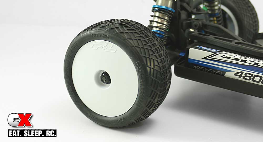
Glue up and install your rear tires.
Step 2:
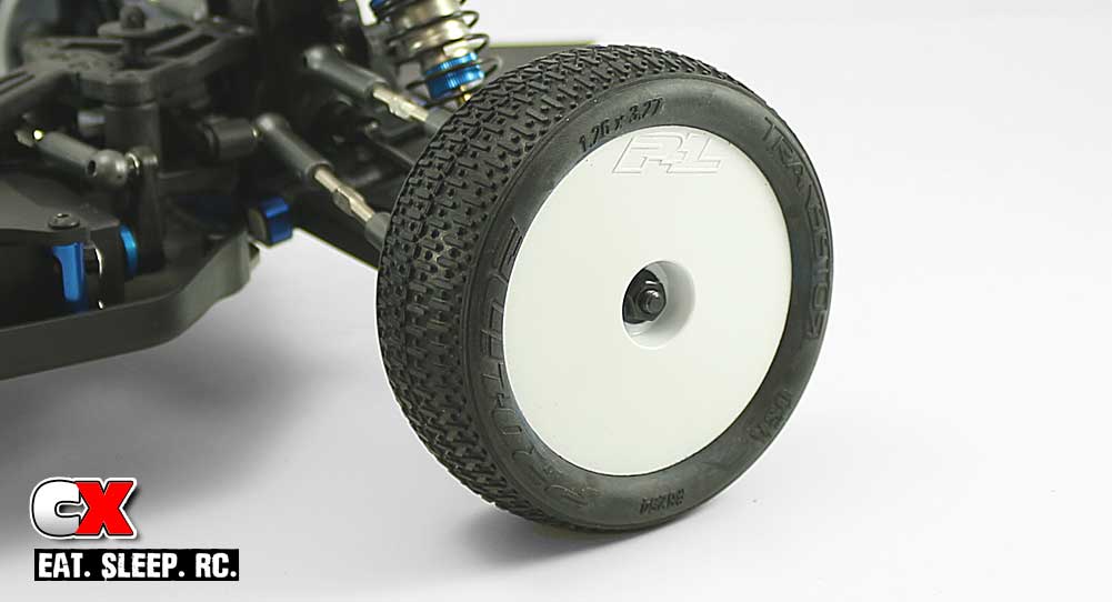
Glue up and install your front tires.
Step 3:
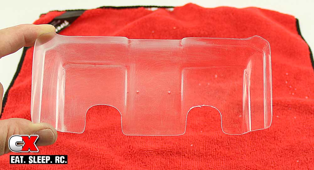
I’m not a fan of clear wings, however I am a fan of clear wings that have been Scotchbrited to give them a better look. Here’s the kit wing that has been partially sanded to remove the see-through look.
Step 4:
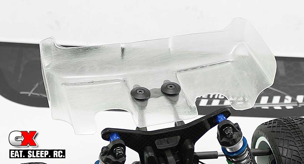
And here it is installed. I need to go over it one more time to uniform the look – but you get the idea.
Step 5:
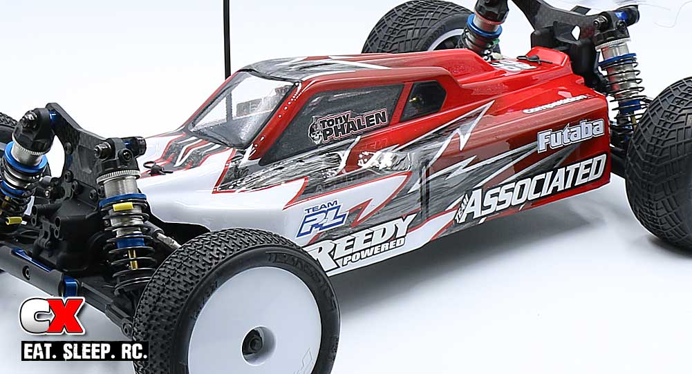
And finally, the B64 Club Racer outfitted with my racing colors! Ain’t she a beauty?
If you’re like me, you can’t wait to get this car out on the dirt! This has been a great build – other than a few minor manual issues, the Club Racer went together in excellent fashion!
Thanks for following along and, if you have any additional questions, please feel free to shoot me a message!

