
Tekno EB48.4 E-Buggy Online Build

Tekno RC’s EB48 platform has been coming on strong over the past couple years. Their newest buggy has added a .4 to the name and features a slew of improvements over earlier models. Of course we were stoked to get one not just to review, but to post up an online build to help those that might need building tips.
Tekno RC EB48.4 E=Buggy Build – Part 1
The first part of our Tekno RC EB48.4 build has us working on the differentials. Both the front and rear are identical, being large fluid-filled units with hardened gears and outdrives. The center diff is similar, the only difference being the main gear.
Build Notes:
© We will be working with diff fluids in this step, so make sure you have a clean work area and some towels handy to clean up any mess you might make.
Step 1:
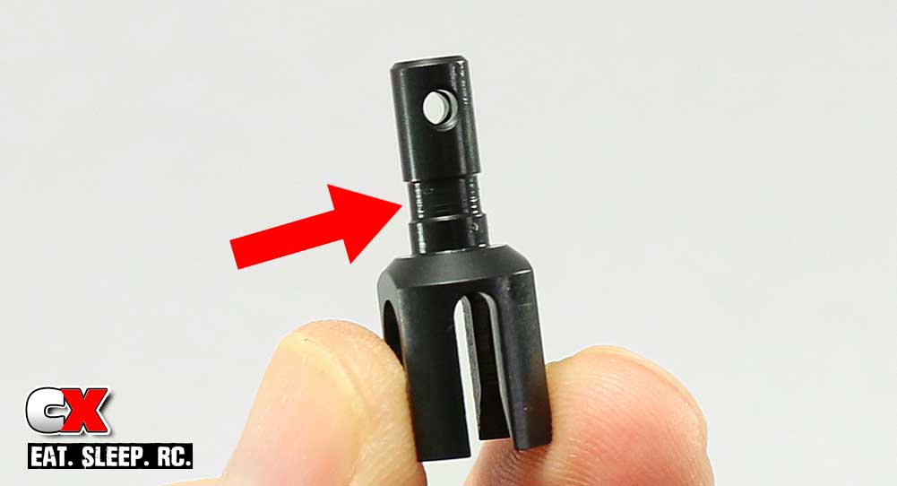
The first thing we need to note is the groove in the outdrives (noted by the arrow). We’ll be applying a liberal amount of black grease here to help keep everything lubed and to reduce wear. Also take note of the hole in the outdrive and its relation to the slot in the cup. You’ll need to reference this in Step 3 and Step 13.
Step 2:
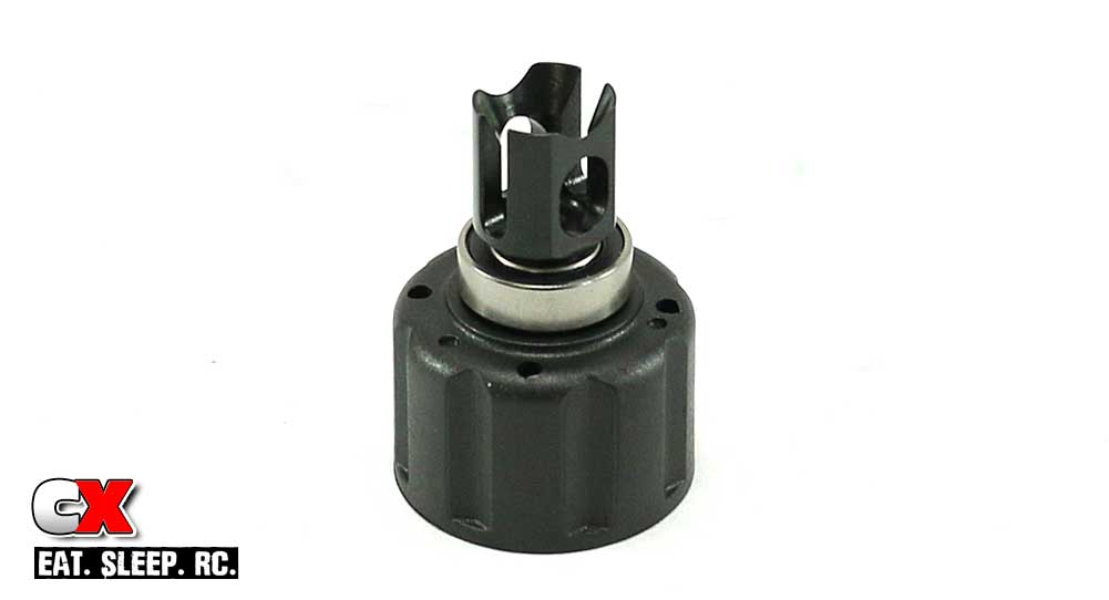
Let’s build the center diff first. Locate one of the three diff cases and press a 8x16mm bearing onto the nub, then drop the lubed outdrive into the hole.
Step 3:

Flip the diff half over, apply a liberal mount of black grease inside the diff housing (around the outdrive shaft) and slide a red o-ring into place followed by a 6x17mm diff shim. Using your newfound knowledge from Step 1, line up the cross pin and slide it through the hole in the outdrive. Key the sun gear to the cross pin and press into place. If you’ve done it right, the outdrive shaft will be flush with the top of the sun gear.
Step 4:
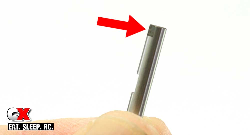
Before we build the small sun gear assemblies, note the flat spots on the notched pins. The arrow points to the flat that is used to key these pins to the differential case.
Step 5:
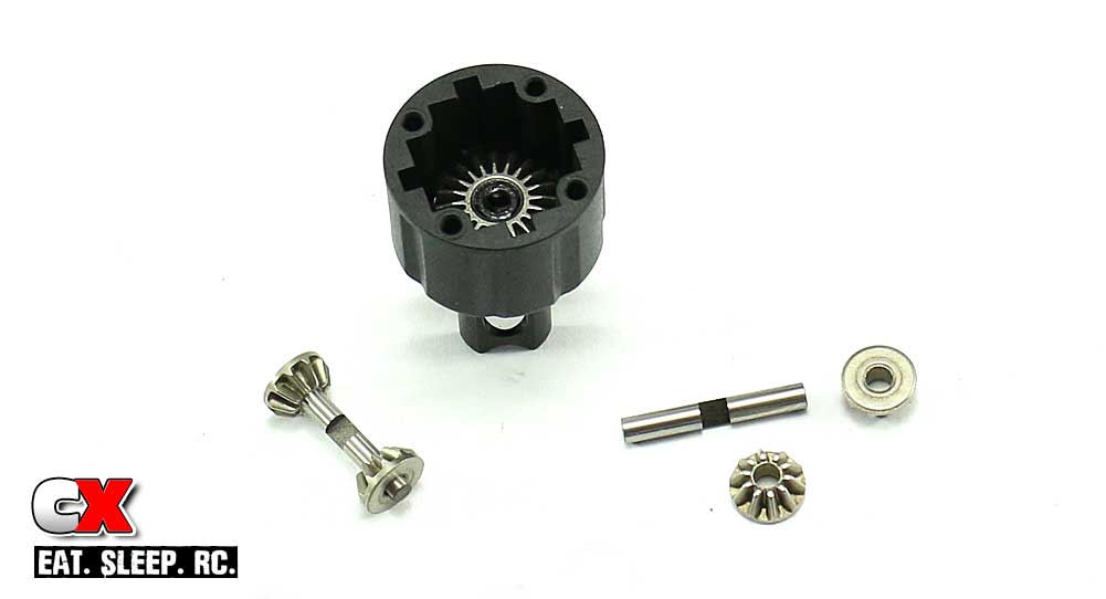
Slide a small sun gear onto the end of each notched pin. Make sure the gear teeth are facing in.
Step 6:
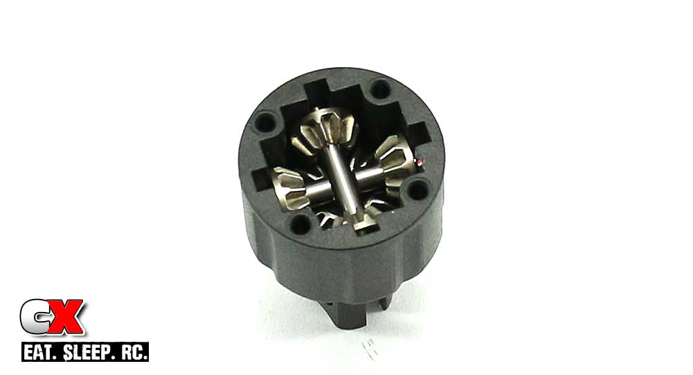
Drop one of the small sun gear assemblies into the diff case. Remember to key the the flat spots on the pins to the case. The first sun gear assembly should have the notch facing up; the second should have the notch facing down.
Step 7:
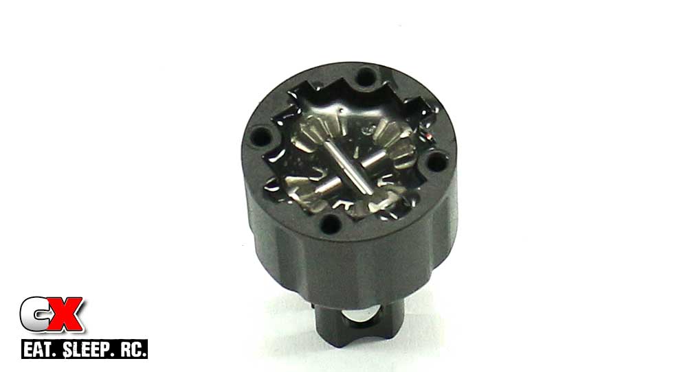
Using the supplied 10K diff oil, fill the diff case all the way up to the top of the sun gears. You may need to rotate the outdrive a couple times to make sure the oil flows into all the nooks and crannies.
Step 8:
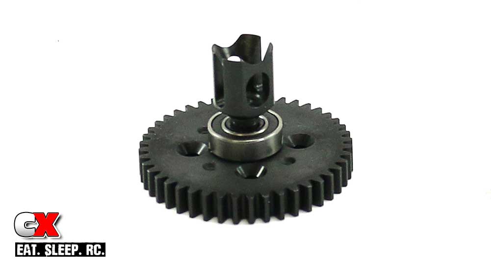
Grab the center diff gear and press on a 8x16mm bearing followed by the outdrive. Don’t forget to lube the outdrive up with black grease.
Step 9:
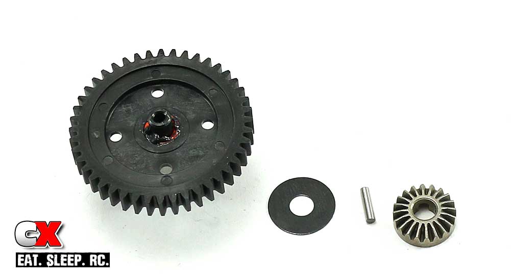
Flip the assembly over, grease up the outdrive shaft and slide the o-ring and 6x17mm diff shim into place. Insert the cross pin (like we did in Step 3) followed by the larger sun gear. Again, if the sun gear is correctly installed, it will be flush with the outdrive shaft.
Step 10:
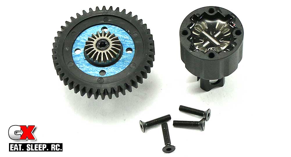
To wrap up the assembly of the center diff, place the blue gasket in place, mate the two diff halves together and secure with the four M3x14mm screws.
Racer Tip: the blue gasket can move around a bit during installation. Apply a small dab of black grease to the gear before setting it in place. This will help keep it in place when mating the two diff halves together.
Step 11:
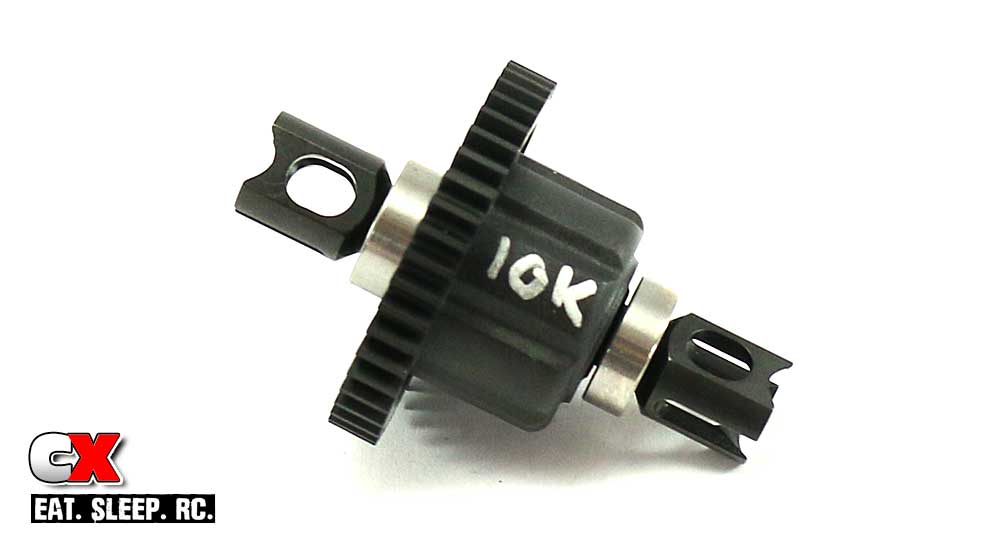
This step is completely optional, but I like writing what fluid is in the diff for easy identification.
Step 12:
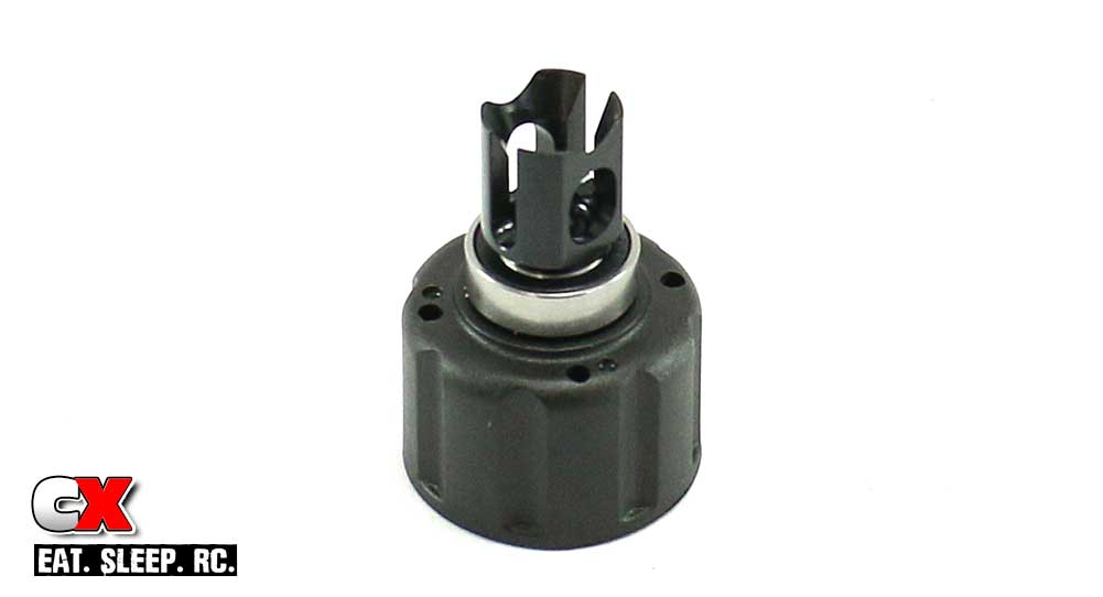
Overall assembly of the front and rear diffs is similar to the center diff, so you can build the two remaining diffs at the same time.
Start by lubing the outdrive, pressing on the 8x16mm bearings and dropping the outdrive into place.
Step 13:
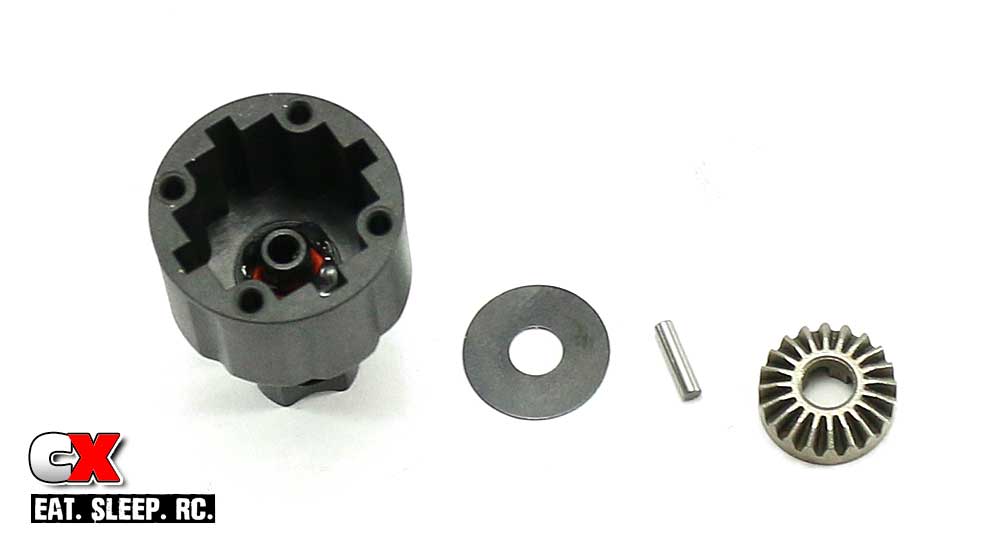
Lube the outdrive (on the inside), install the red o-rings, 6x17mm shims, cross pins and larger sun gears.
Step 14:
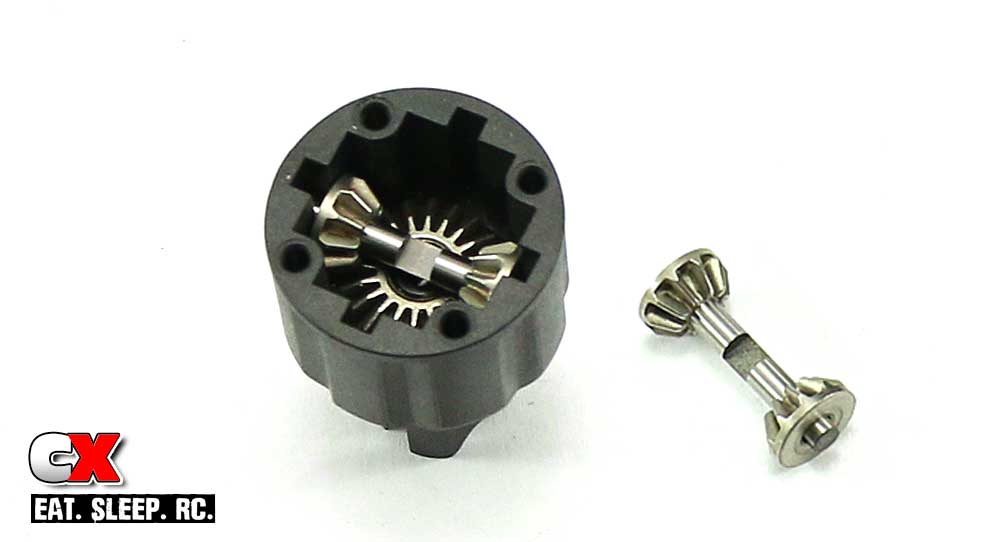
Build your two (or in this case, four) smaller sun gear assemblies and install.
Step 15:

Fill one diff with 10K fluid (this will be your front diff) and one with 7K fluid (this will be the rear diff – DON’T MIX THEM UP). Set the blue gasket in place, mate the two diff halves together and secure with the four M3x14mm screws.
Step 16:
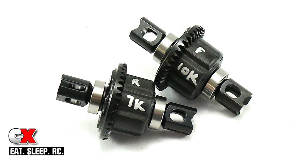
Scribble the weight and location of the diffs on the housings as shown.
Part 1 of our build is done! Set your diffs aside, clean up any mess you might have made and let’s move on to the bulkheads and suspension.
Tekno RC EB48.4 E=Buggy Build – Part 2
Part 2 of our Tekno RC EB48.4 build involves the bulkheads and suspension, both the front and rear. There is alot going on in this step, being quite a bit longer than usual. We’ll take a break in the middle so you can get a drink, grab a snack or visit the potty.
Build Notes:
• The front and rear gearbox cases are different; the front has a slight upward angle at the output shaft while the rear is straight. Make sure you don’t mix these up during the build.
Step 1:
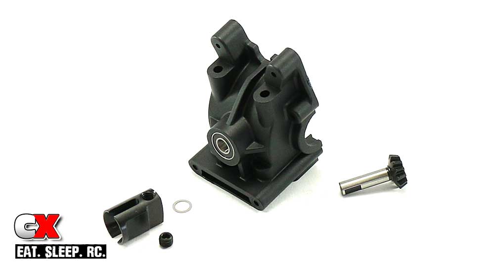
Step 1 is to assemble one half of both the front and rear gearboxes. Start by pressing the 5x13mm bearings into each side of the boxes, then insert the input shaft through the bearings from the inside. Slide the 5x7mm shim onto the input shaft followed by the drive cup. Line up the flat spot on the input shaft with the hole in the drive cup and secure with the M5 grub screw. Use a drop of blue threadlocker to ensure the grub screw doesn’t back out.
Set the front gearbox half aside; we’ll be working with the rear one first.
Step 2:
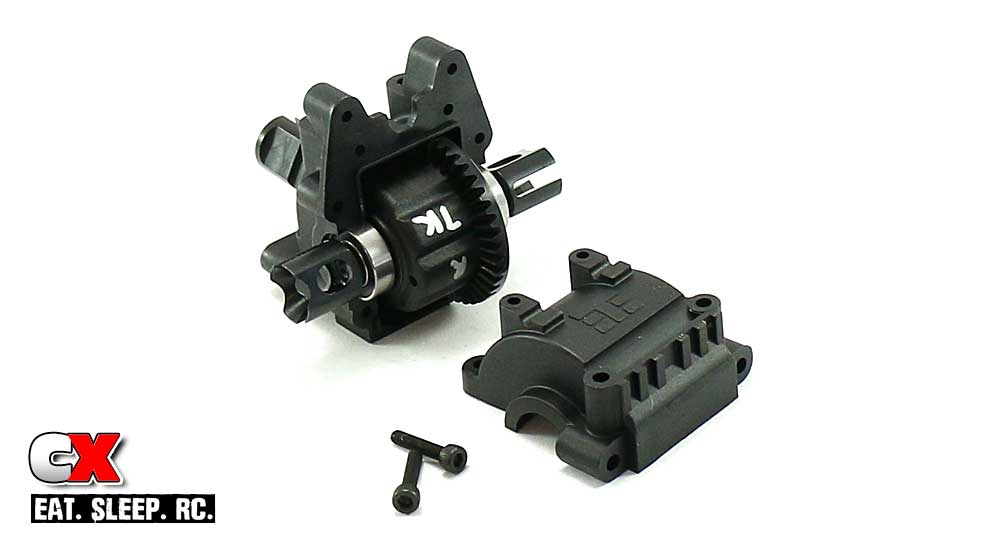
Grab your rear differential assembly (you did keep track of which one is the rear one, right?) and install it into the the bulkhead as shown. Attach the gearbox cover with the M3x14mm screws.
Once assembled, rock the differential side-to-side to see if there is any play. If there isn’t, move to Step 3. If there is, open the gearbox and add a 1mm shim to the gear side of the diff. Re-assemble and rock side-to-side again. If there is still play, open and add another 1mm shim to the diff, this time on the opposite side of the gear. Re-assemble; there shouldn’t be any play at this time.
Step 3:
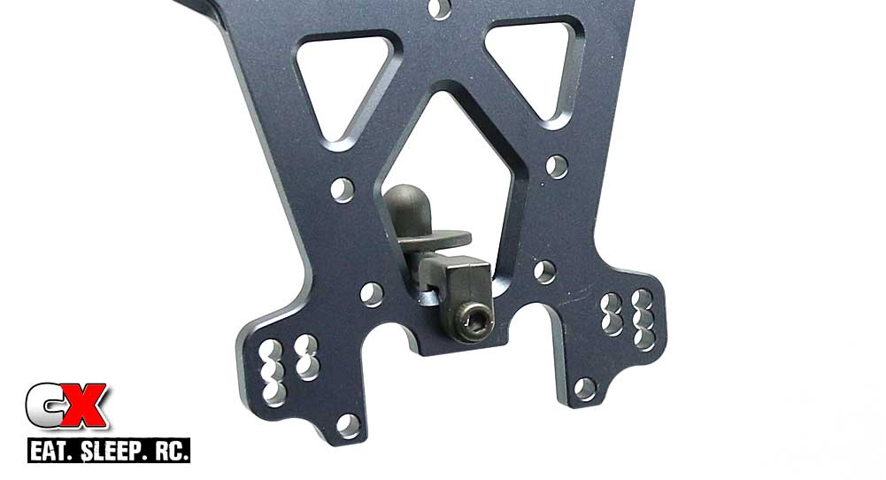
Attach the rear body mount to the rear shock tower as shown.
Step 4:
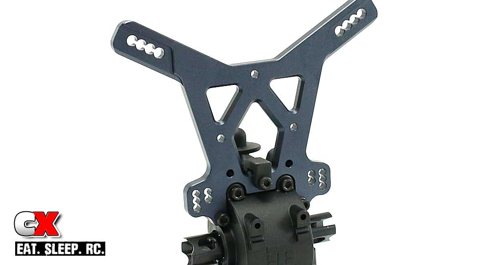
Attach the rear shock tower to the gearbox. Note the orientation of the upper shocks mounts on the tower.
Step 5:
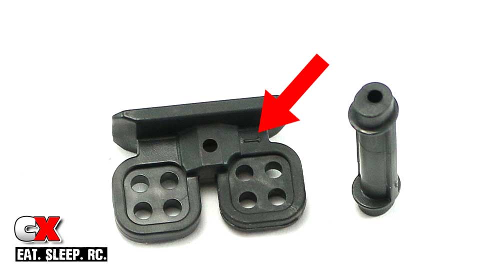
To finish off the rear bulkhead, we need to assembly the rear wing mounts. Notice the small arrow on the mount (notated by the red arrow). This points to the front of the wing mount and helps us identify the wing position settings.
Step 6:
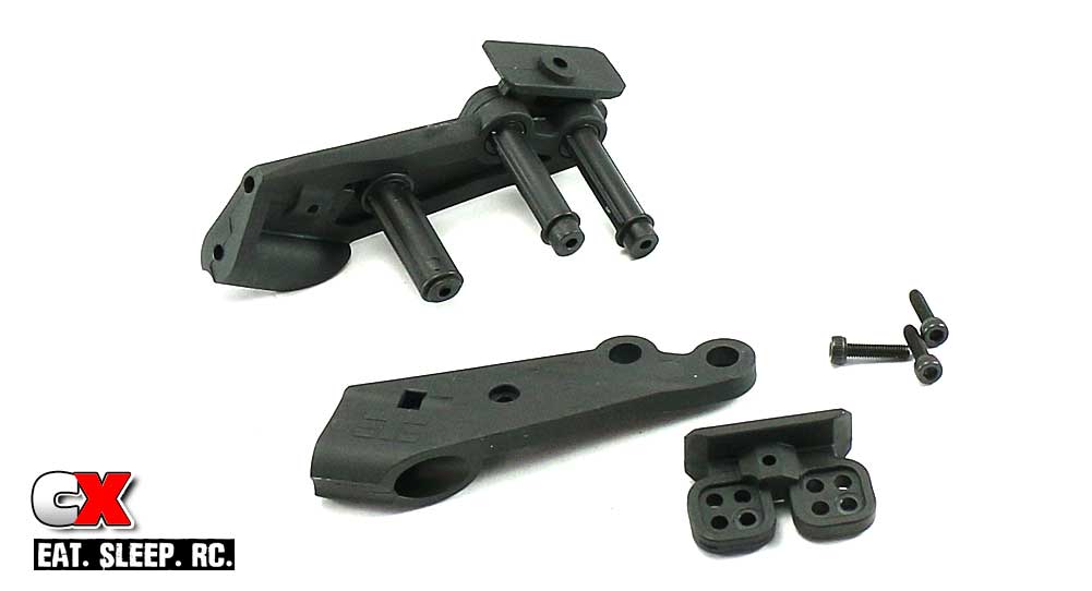
Attach the plastic cross braces to one side of the right wing mount as shown. The kit suggests a #2 forward setting, however we’ll be building it with a #1 forward. Note the two upper cross braces; the mounting hole is offset, mounted ‘up’ in this part of the build.
Step 7:
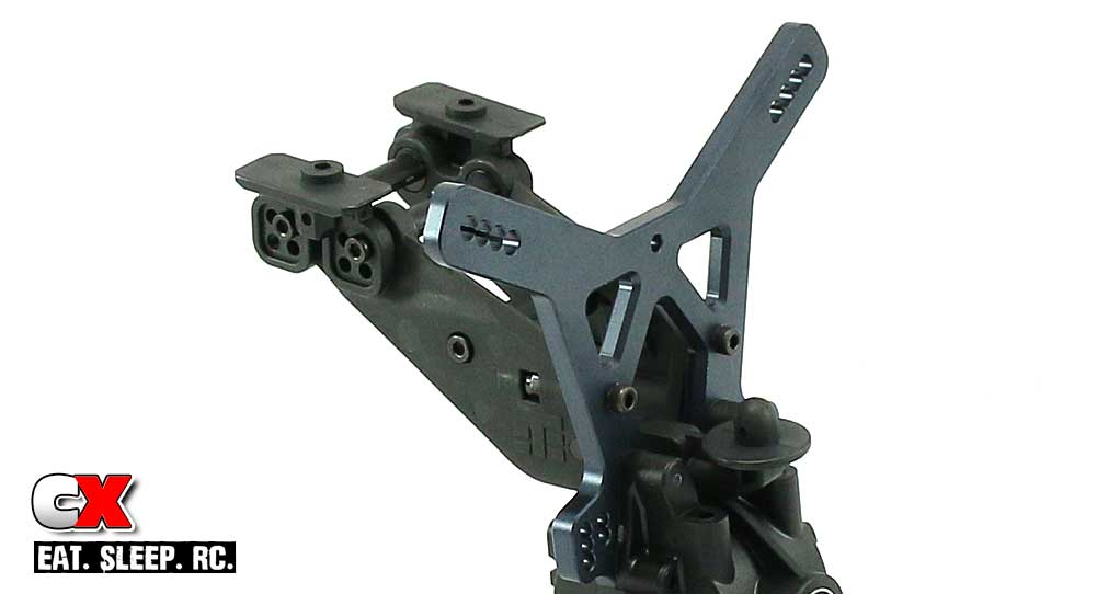
Once your wing mount is complete, attach it to the rear shock tower with the 4 M3x20 screws. Don’t forget to press the M3 locknuts into the recesses in the wing mount.
Step 8:
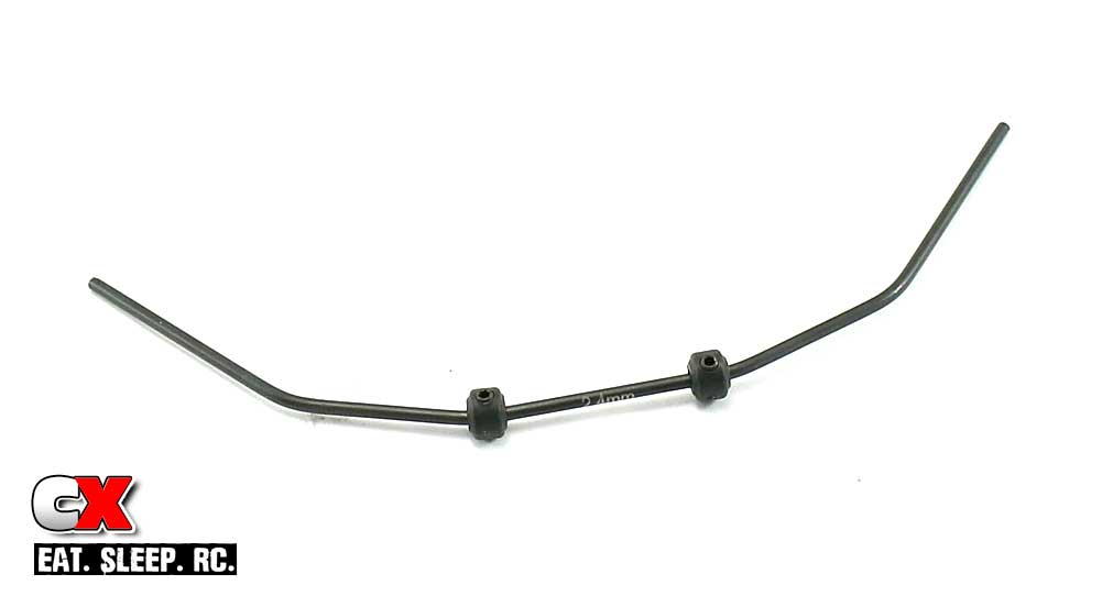
Insert the M3 grub screws into the stops and attach them to the rear, 2.4mm anti-roll bar. The manual shows a distance of 30.2mm between the stops; I suggest keeping them a little farther apart at the moment.
Step 9:
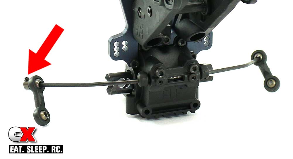
Set the anti-roll bar into place and install the plastic brace. Center the anti-roll bar and slide the stops from Step 8 closer together until they just barely touch the brace; the anti-roll bar should swing freely. Tighten the M3 grub screws in the plastic brace until they make contact with the anti-roll bar, then back them off a smidge. The grub screws are there to keep the anti-roll bar from wobbling but not to hinder movement. Again, make sure the anti-roll bar swings freely.
Assemble the anti-roll bar links and attach to the bar. Note the orientation of the ball mounts (red arrow). Slide the ball mount onto the anti-roll bar until it is flush with the end of the bar, then insert and tighten the M3 grub screw. A very light drop of blue threadlocker is suggested here.
Step 10:
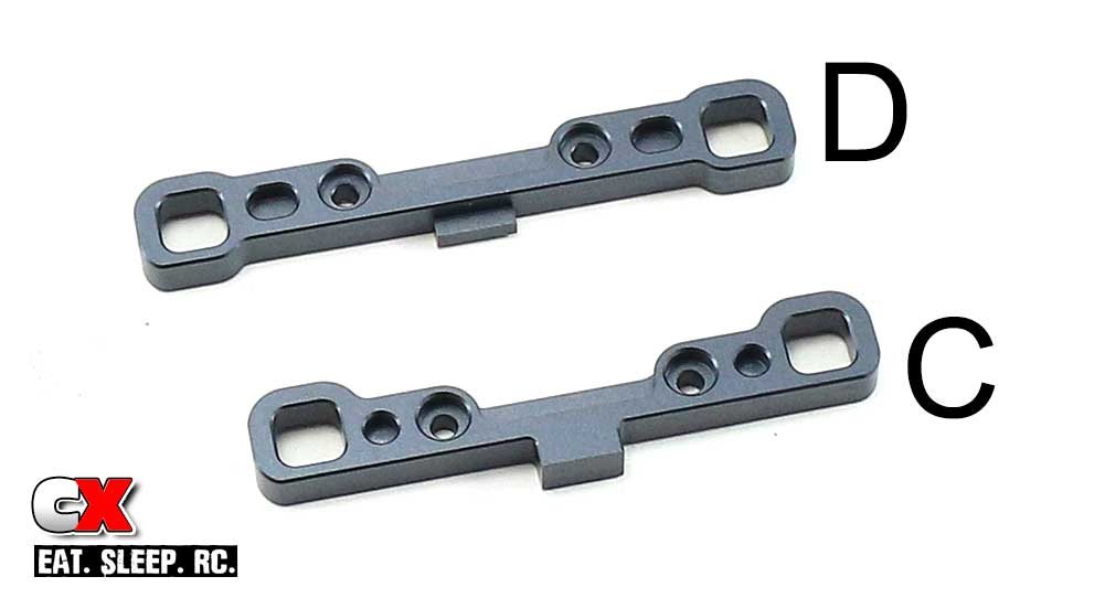
We’ll be attaching the C and D mounts now; here’s a quick pic of both of them together. Grab the C mount.
Step 11:
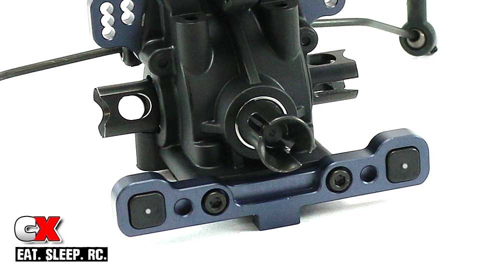
Press a pair of 1-middle inserts into the C block; I’ve highlighted the pip in the picture. Attach the C block to the bulkhead using a pair of M3x14 screws.
Step 12:
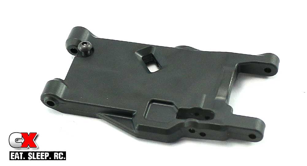
Grab your rear arms and insert the droop screw from underneath as shown. We can’t adjust droop just yet, so I inserted them until the head was level with the arm. Just make sure both screws are equal at the moment.
Step 13:
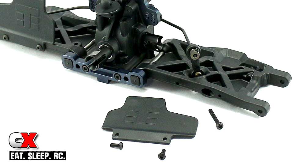
Insert the hinge pins into the C mounts, then slide the rear arms into position; note the orientation. Connect the anti-roll bar with the M3x20 screw as shown, then attach the rear mud guards.
Step 14:
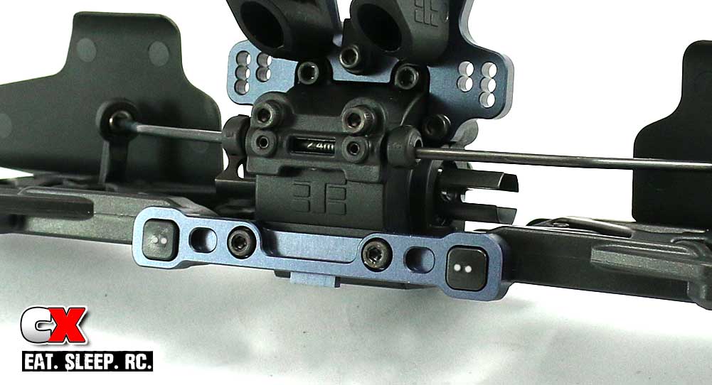
Press the 2-inner inserts into the D block (I’ve highlighted the pips). Align the rear hinge pins with the D block and attach it to the rear bulkhead with the M3x40 screws. Make sure both arm assemblies swing freely.
Step 15:
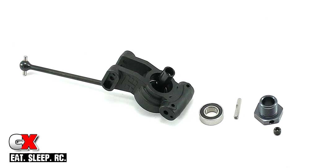
Grab your rear hubs and press the 13x19mm and 8x16mm bearings into place. Slide the pre-assembled CV axle in and through the 17mm hex. Insert cross pin and secure with the M5 grub screw – use blue threadlocker here.
Note that the cross pin has a flat spot on it – you’ll want the M5 grub screw to land on that spot when tightening it down.
Step 16:
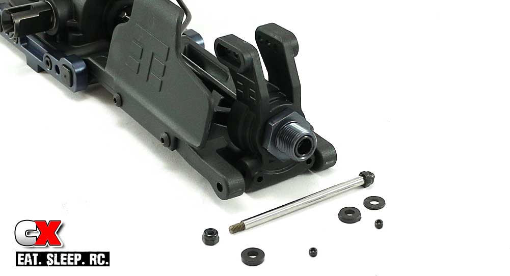
Start this step by attaching one of the M3 locknuts to the rear hinge pins. Set the assembled rear hub into place and slide the hinge pin through the holes to capture it. You will also be inserting wheelbase spacers here; the kit setup uses a thick spacer up front and a thick and thin one towards the rear. Once assembled, secure the hinge pin with another M3 locknut.
Step 17:
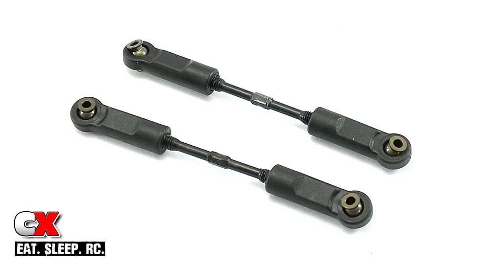
Build a pair of rear camber links. The 38.3mm length is a good starting point.
Racer Tip: To make them easier to screw on, apply a small amount of grease or even chapstick; this works great!

We’re halfway through – you’re doing great! Get up, stretch and get a quick snack. I’ll wait.
Step 18:
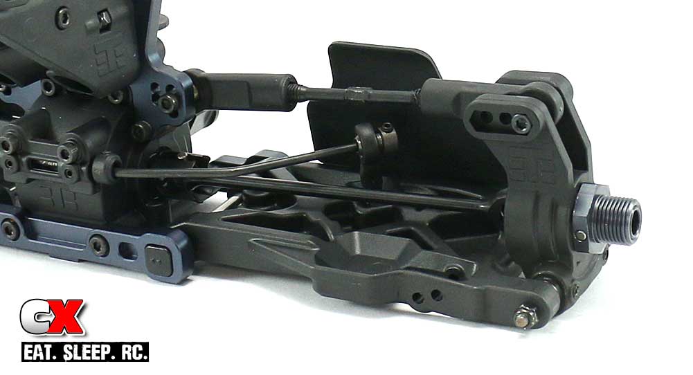
Key the dogbone to the outdrive and attach the rear camber link in the 4C position (see manual for the coding diagram). It is also suggested that you install them with both of the turnbuckle ‘notches’ facing the left side of the car, or driver’s side.
Note that the tower screws are shorter (M3x20mm) than the hub screws (M3x22). Don’t get these mixed up.
Step 19:
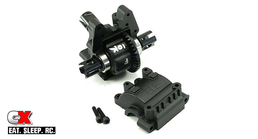
Grab your front gearbox (it has the angled output shaft) and set the front differential into place. Attach the gearbox cap with the two M3x14mm screws.
Step 20:
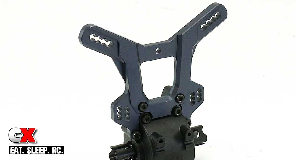
Attach the front shock tower to the gearbox; note the orientation of the upper shock mounting holes.
Step 21:
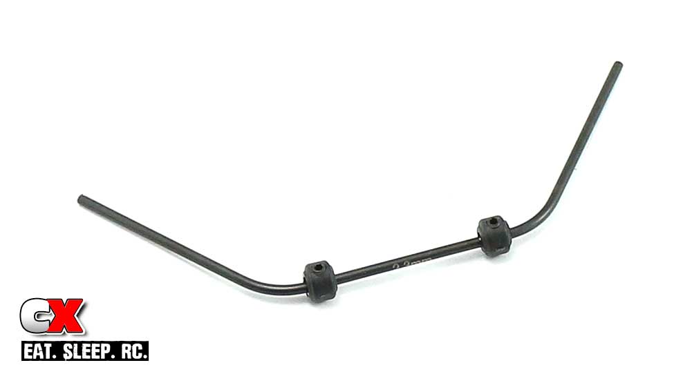
Assemble the front, 2.3mm anti-roll bar like you did the rear. Spacing suggests 30.2; I’d make this a little wider as well.
Step 22:
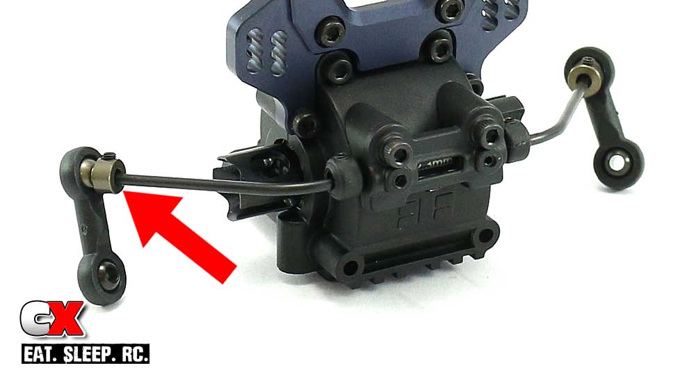
Attach the bar to the bulkhead, capture it with the plastic cap and use the M3 grub screws to keep the bar from wobbling.
Build the links, but this time install them with the ball mount opposite from the rear (see the red arrow). Slide the ball onto the anti-roll bar until it is flush with the end of the bar, insert the M3 grub screw and tighten it down. A very light drop of blue threadlocker is suggested here.
Step 23:
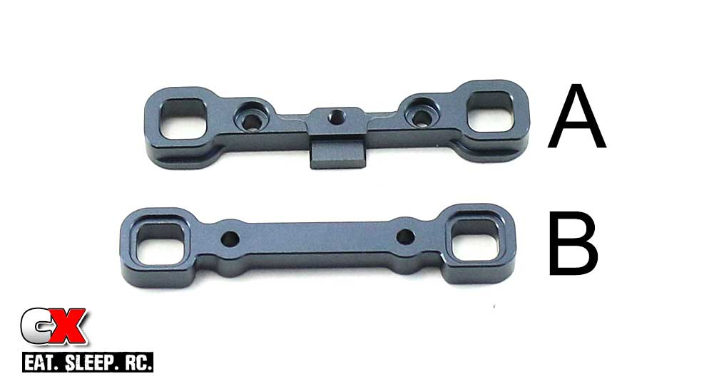
A closer look at the A and B arm mounts. Grab the B mount.
Step 24:
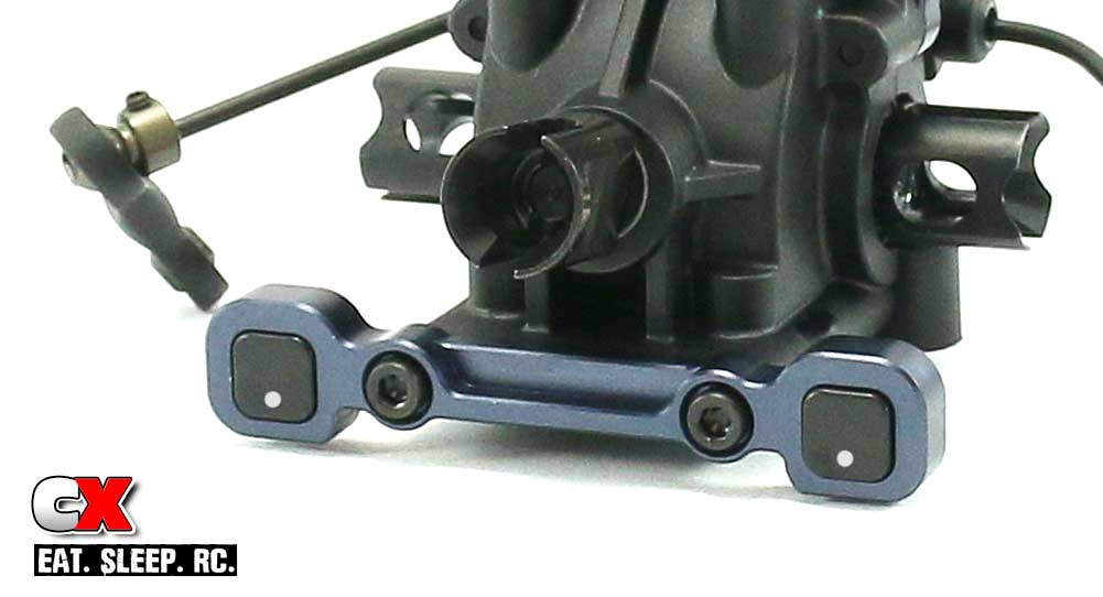
Press the 1-down inserts into the B mount and attach it to the bulkhead with the M3x14 screws as shown. I’ve highlighted the pips so you can see the orientation.
Step 25:
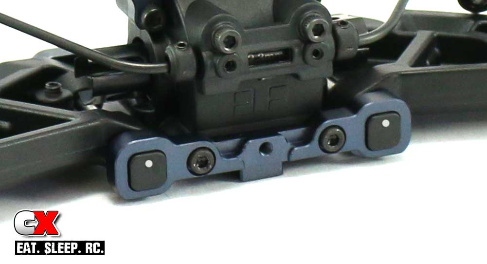
Insert the droop screws into the bottom of the front arms (if you haven’t already done this), making them equal on both sides. Again, I set them to where the head of the screw is level with the bottom of the suspension arm.
Insert the hinge pins into the B block and slide the arms in place (arm ‘cutouts’ towards the rear of the bulkhead).
Press the 1-up inserts (again, more highlighted pips) into the A mounts and attach to the bulkhead with the M3x40 screws.
Step 26:
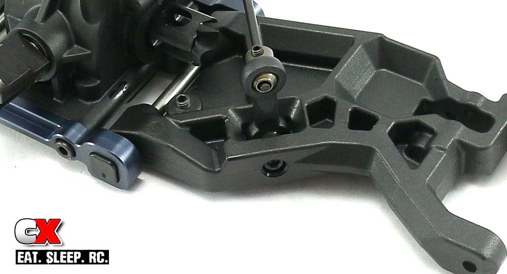
Attach the anti-roll bar to the arms with the M3x20 screws. This view also gives you a better look at the arm mount orientation.
Step 27:
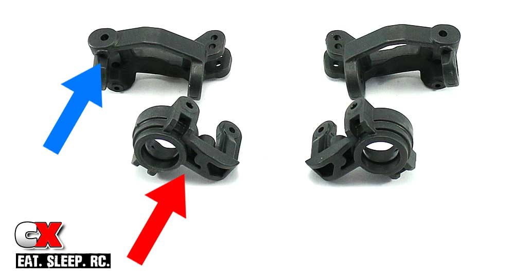
Before we assemble the caster blocks and steering arms, take a close look at the picture to see the orientation of the parts.
The red arrow shows the raised part of the steering arm. The blue arrow shows the identifying screw hole for a later step. Make sure you group these parts together like this; the group on the left is for the left side of the car (driver side), the group on the right for the right side.
Step 28:
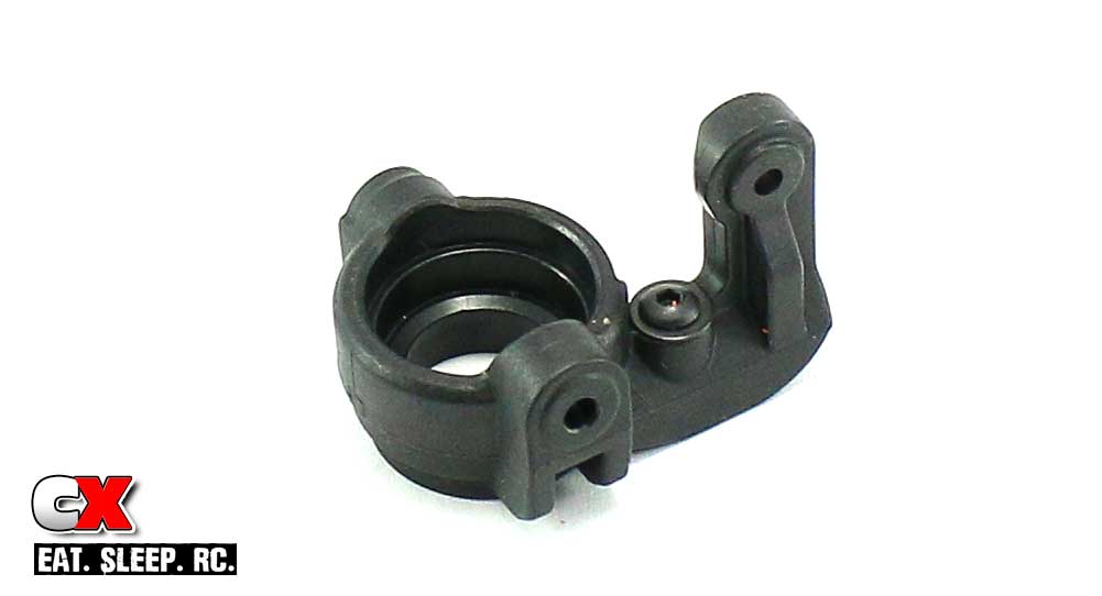
Insert a M3x6 screw and 8mm washer into each steering arm. These act as mechanical steering stops.
Step 29:
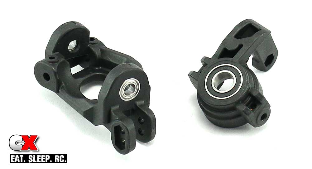
Press the 5x10mm bearings into the top and bottom of each caster block and a 13x19mm and 8x16mm bearing into each steering block.
Step 30:
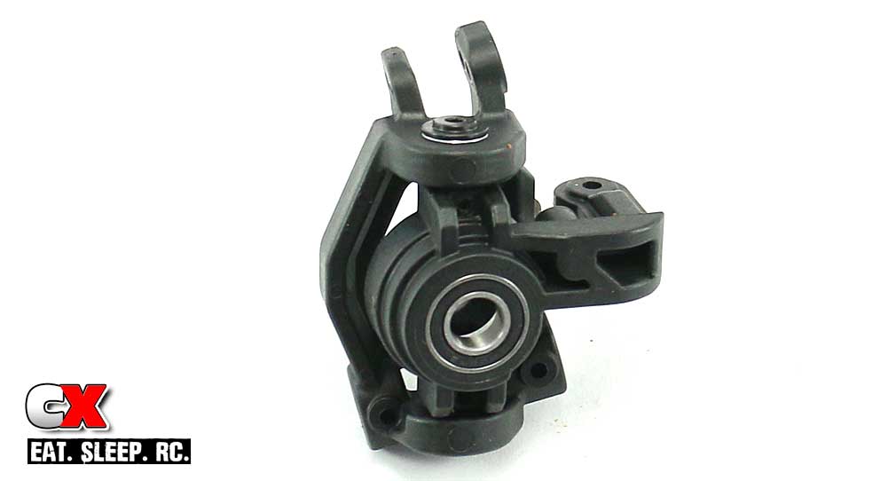
Mate the steering block assembly and the caster block assembly together and secure with the upper and lower kingpin screws. Since they don’t thread in, you’ll need to capture them with the M3 grub screws. DO NOT overtighten these screws; snug them up and then give the kingpin screw a tug to make sure it is secure.
Step 31:
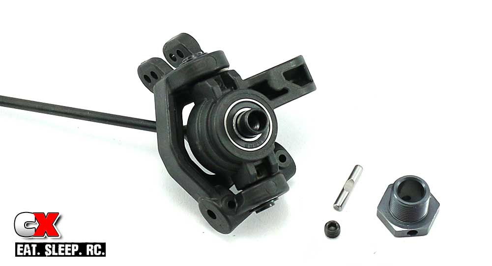
Slide the assembled CV axle through the steering assembly followed by the 17mm hex. Like the rear, you’ll want to insert the cross pin through the hex and secure with the M5 grub screw. Make sure the grub screw hits the flat spot on the cross pin. Blue threadlocker is suggested here.
Step 32:
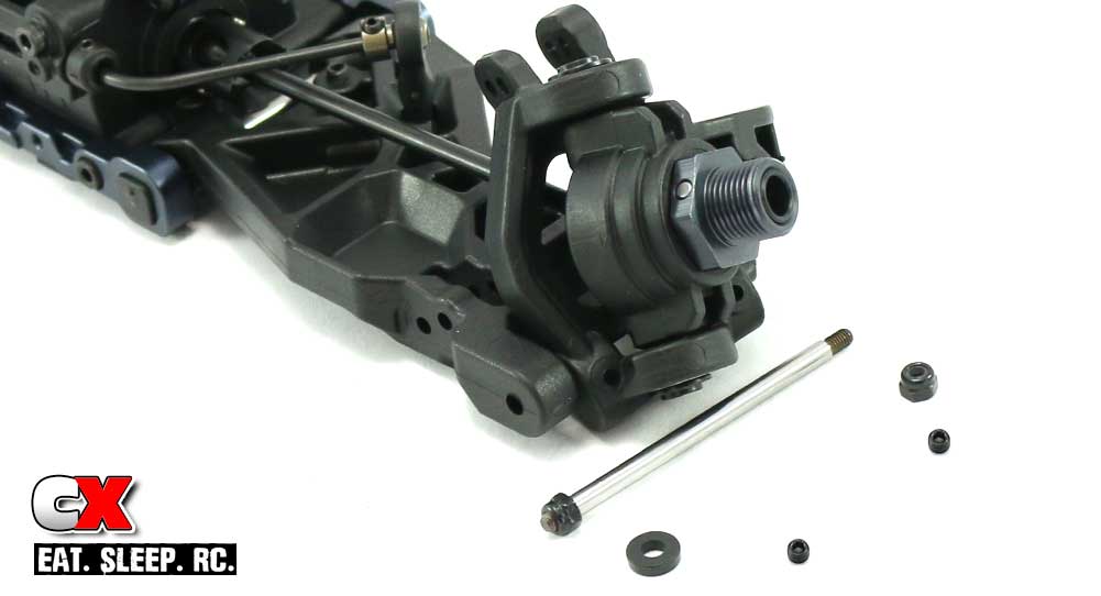
Place the steering assembly into place on the front arm as shown. Attach a M3 locknut to one end of the hinge pin and slide it through the arm and steering assembly. We’ll be using a wheelbase spacer here as well; include it in front of the steering assembly. Add another M3 locknut to the hinge pin.
Screw the two M3 grub screws into place to keep the hinge pin from rotating. Remember, do not overtighten these!
Step 33:
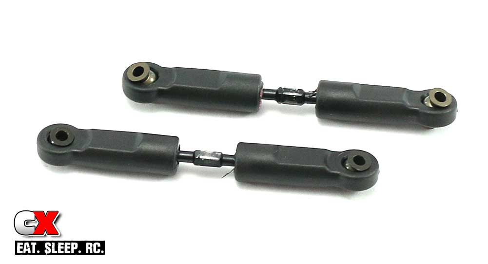
Build the front camber links; the kit suggested 14mm is a good start. Note the balls that insert into the rod ends are different; one has a flange, one doesn’t. It’s imperative that the flanged ball mounts to the tower.
Step 34:
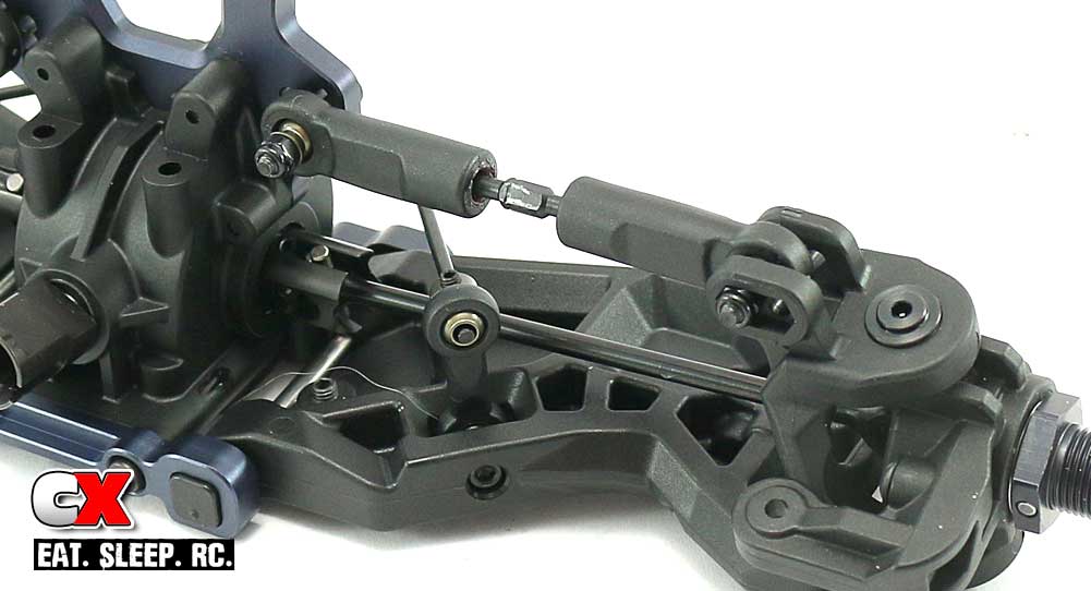
Insert the CV axle into the diff outdrive and attach the camber link to the 5A position. (see manual for the coding diagram). Match the turnbuckle notches to the ones on the rear of the buggy; they should be set to the left side of the car.
Whew – that was a pretty long step! But, you’ve got a pretty good looking set of front and rear clips ready for installation! Let’s move on to the steering.
Tekno RC EB48.4 E=Buggy Build – Part 3
Next up in our Tekno RC EB48.4 build is the steering. This buggy uses a bearing-supported dual bellcrank setup with adjustable bumpsteer and Ackermann. It also integrates a bellcrank mounted servo saver to help protect your expensive servo.
Build Notes:
• None.
Step 1:
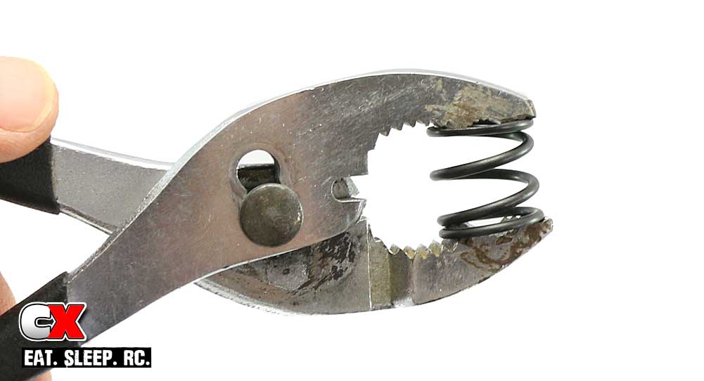
Before we can assemble the steering system, we have to prep a few of the parts. The first thing we need to do is pre-compress the servo saver spring as few times with a set of large pliers. This will make it easier to compress after it is installed.
Step 2:
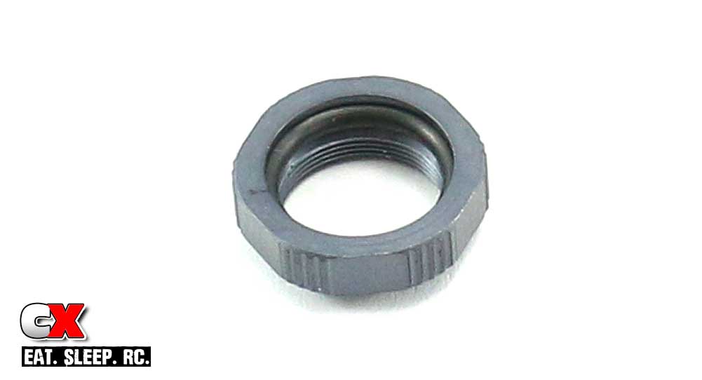
Next, you’ll want to insert the o-ring into the collar. The instructions suggest blue threadlocker on the collar threads to keep it from backing off. If you do decide to use some, use it very sparingly. I’ve never encountered a servo saver of this design loosening up, however as a precaution I did add a very small to this one.
Step 3:
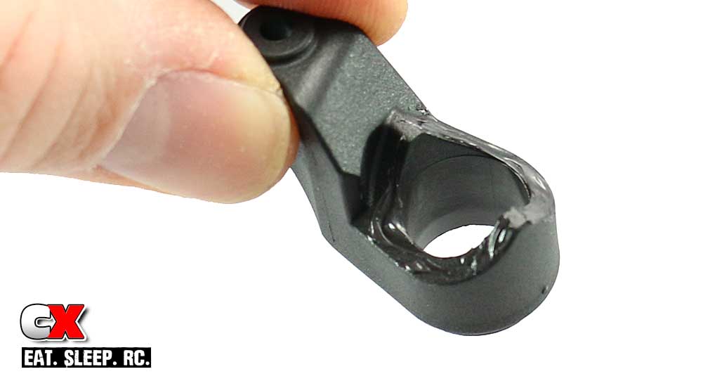
Here’s a little trick I learned a REALLY long time ago. Adding a little bit of black grease to the servo saver parts keeps them lubed and in good condition. Dry, the constant rubbing together can cause them to wear prematurely. Just a tad on one side is all that necessary.
Step 4:
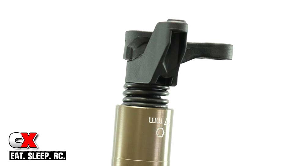
Now assemble the servo saver side of the steering. You can use a 17mm wrench to tighten the servo saver collar down. Per the instructions, tighten all the way and then back it off 3 full turns.
Step 5:
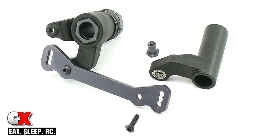
Press the 5x8mm bearings into both sides of the bellcrank arms. Insert the M3x10 screws through the top of the steering rack, through the bearings and into the steering rack bushings. The bushings will reside in between the bearings for a silky smooth steering feel. Blue threadlocker is suggested here.
Step 6:
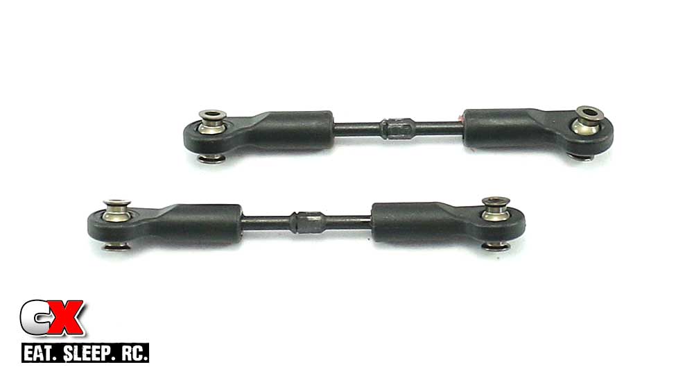
Build a pair of steering links. Note the direction of the ball cups. The 26.5mm length is a good starting point.
Step 7:
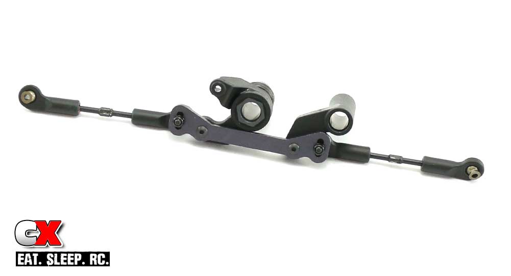
Attach the steering links to the steering rack using the center hole. Make sure you include the four M3x8mm washers on each side. These washers control bumpsteer and are very important. Also note the turnbuckle notches are facing the left side of the buggy.
Step 8:
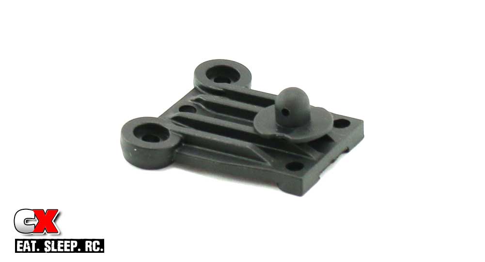
Attach the front body mount to the steering top plate.
Step 9:
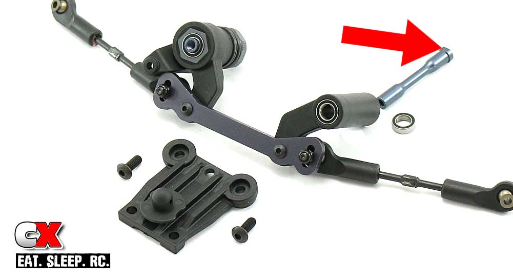
Press the 6x10mm bearings into the top and bottom of the bellcranks. Slide the steering posts up through the bearings and attach the steering top plate.
Note the red arrow – this points to flat spots on the steering posts. These flat spots will key to cutouts on the chassis in Step 11.
Step 10:
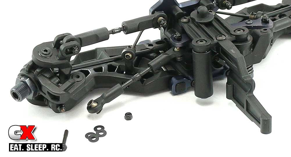
Install the front chassis brace to the steering assembly, then connect the completed steering assembly to the front bulkhead with the M4x10 screws, but don’t tighten all the way just yet.
Connect the steering links to the steering arms, including four M3x8 washers per side.
Step 11:
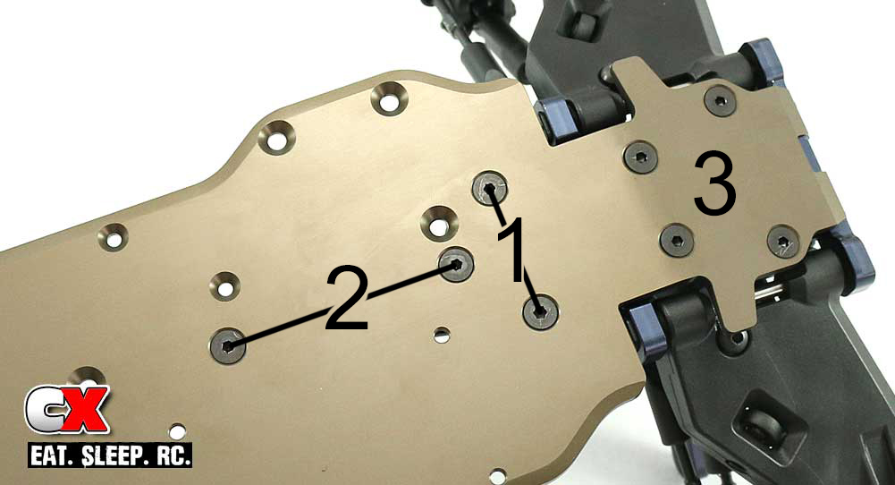
Attach the entire front clip to the chassis, making sure the steering post flat spots key to the cutouts in the chassis. I’ve included an underside picture so you can see which holes are used for this step.
The best order I found was to start with the two M4x10 screws (labeled 1, use blue threadlocker) followed by the two M4x12 screws (labeled 2). Once those are started, finish up the step by inserting the four M4x12 screws up front (labeled 3). Once all of them are started, you can snug them all down slowly to make sure you don’t tweak anything.
After you’re done tightening the chassis screws, flip the buggy over and tighten up the two M4x10 screws you left loose from Step 10.
Step 12:
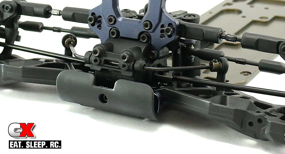
The final step is to attach the front bumper. Easy peasy.
Yup, it’s starting to look like a buggy. Great job – let’s get cracking on the center diff and rear clip install.
Tekno RC EB48.4 E=Buggy Build – Part 4
Part 4 is going to be a really easy one – I’m making up for the super long Part 2! We have 3 steps – installing the center differential and the rear clip.
Build Notes:
• Once you get this step complete, rotate the drivetrain to make sure everything spins smoothly. If there is a bind, start by removing the center bulkhead and test each end of the car individually.
Step 1:
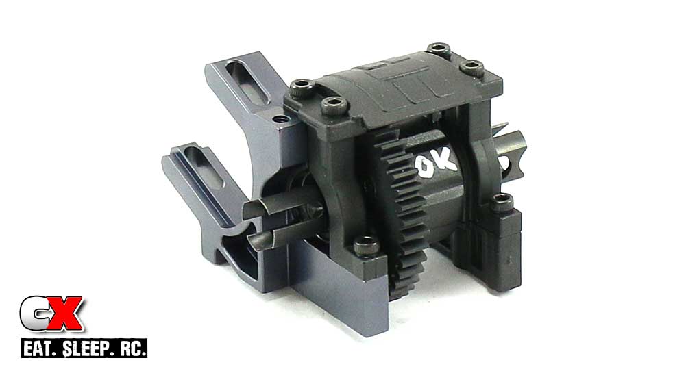
Assemble the center diff housing, but don’t tighten up the screws until the entire assembly is complete. Use a little bit of blue threadlocker on the top two M3x12 screws that feed into the aluminum motor mount. Make sure you install the diff with the correct orientation as well.
Step 2:
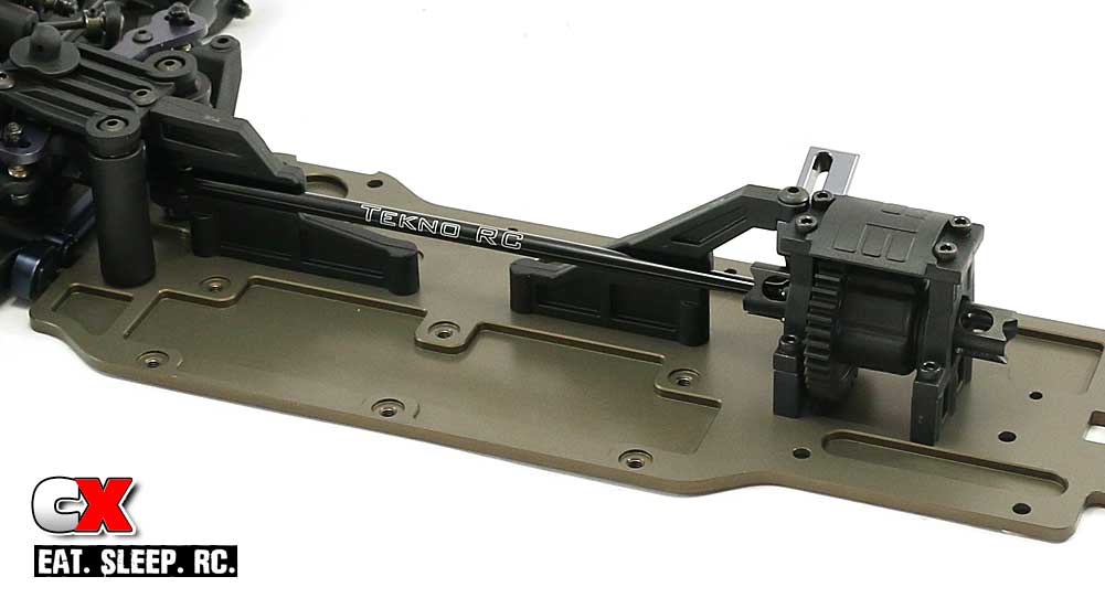
Attach the plastic chassis brace to the center diff housing with a M4x10 screw, using blue threadlocker to help keep it in place.
Insert the long driveshaft into position and attach the center diff housing assembly (and chassis brace) to the chassis. Two of the M4x12 screws (the ones that thread into the aluminum motor mount) will require blue threadlocker.
Step 3:
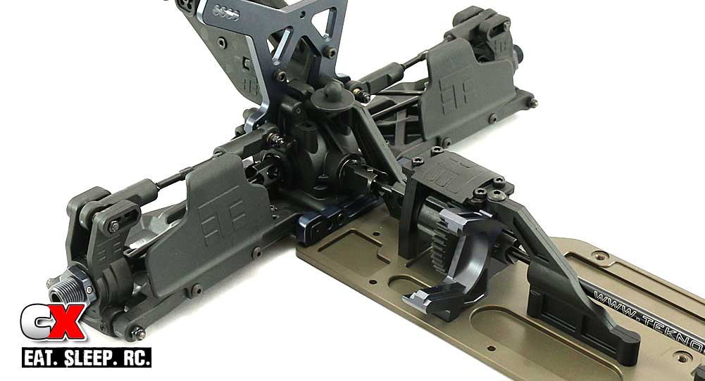
Insert the shorty driveshaft into position and attach the rear clip to the chassis. Finally, attach the rear chassis brace from the rear clip to the chassis.
See, short and sweet! Time to ramp the pace back up with the shocks. Let’s get to ’em!
Tekno RC EB48.4 E=Buggy Build – Part 5
Ok, time for some shock action! The Tekno RC EB48.4 comes with a stellar set of dampers. Everything on these shocks is new, from the bodies to the internals. Even the springs are touted as new ‘Low Frequency’ springs. Let’s get ’em built!
Build Notes:
• Shock building is always a challenge, so there’s a good chance things might get messy. Make sure your work area is clean and you have some rags handy for clean up.
• I’d also suggest some sort of shock stand to hold the shocks while you’re waiting for the bubbles to rise out of the fluid.
• While noted in the actual build step, I think it’s important to point out that Tekno uses two different types of lower screws for the shocks; a standard thread and a reverse thread. This helps prevent the screws from backing out when the suspension arms move up and down. See the steps below for actual placement.
Step 1:
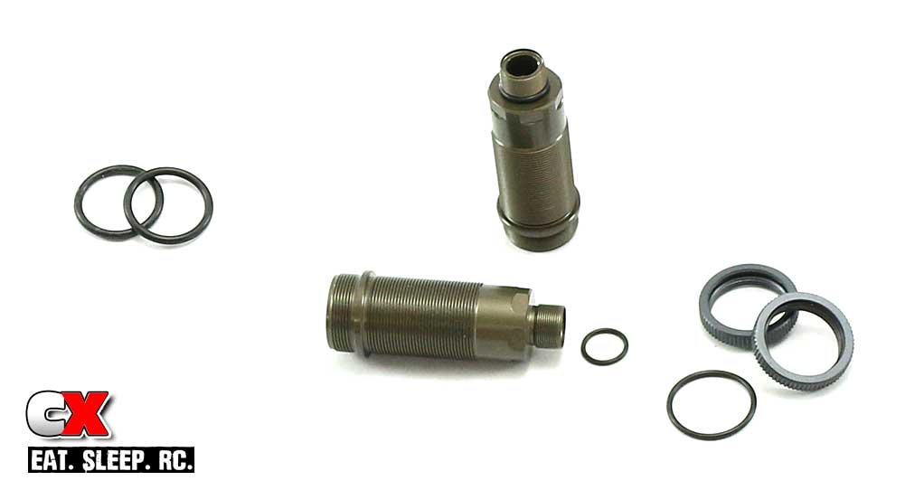
Before assembly, let’s take a closer look at the different o-rings included with the shocks. There are three; the smallest ones, used for the bottom of the shocks; the skinny/bigger ones, used with the threaded collars and the thick/bigger ones, made to be installed in the shock caps.
For the first step, go ahead and install the smaller o-rings onto the bottom of the shocks and the ones in the threaded collars.
Step 2:
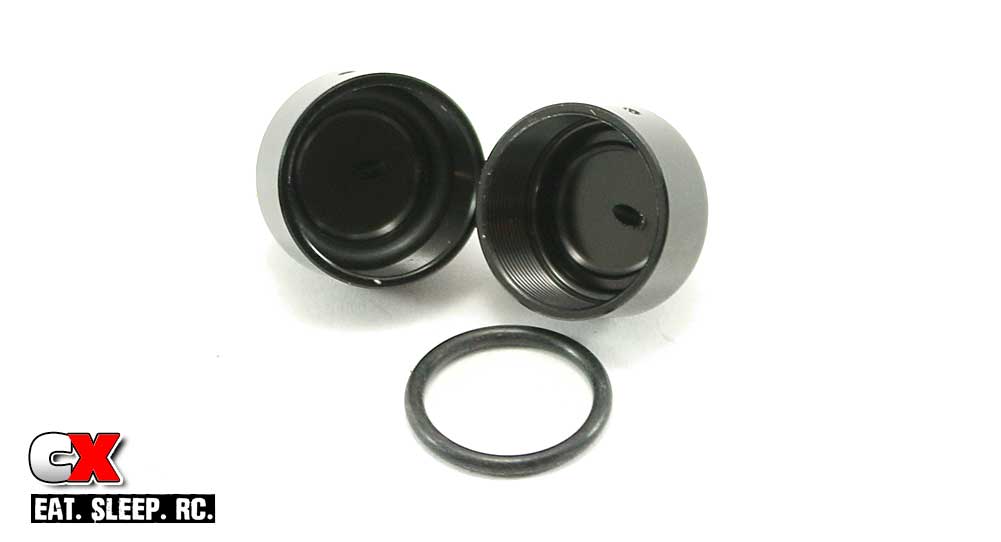
Now install the thicker o-rings into the shock caps. They should seat all the way down inside.
Step 3:
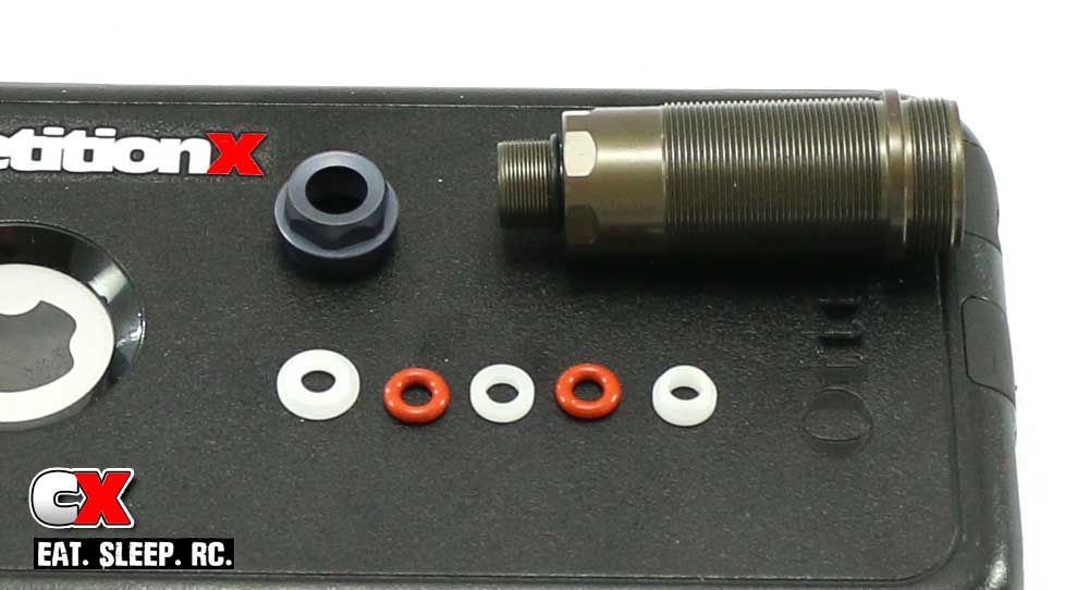
Tekno’s shocks use a bottom cartridge design; everything installs from the bottom of the shock. I’ve laid out the pieces in the order they install; use a small drop of shock oil during assembly to allow them to slide into the shock easier.
Also note the orientation of the plastic shock guides.
Once the cartridge pieces are installed, screw on the bottom shock cap. Build all four.
Step 4:
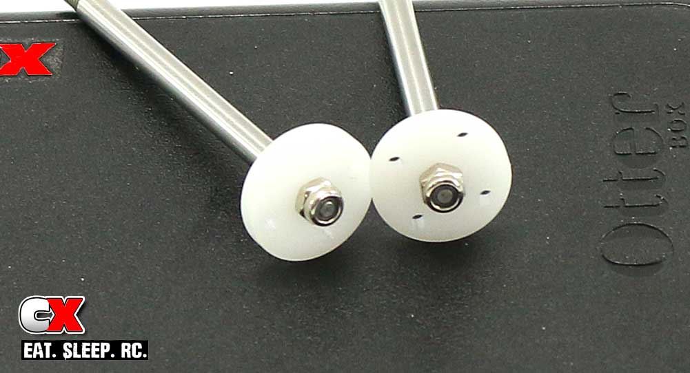
Attach the pistons to the shock shafts. All four pistons are the same for the kit setup, so the only difference is going to be the length of the shock shafts; shorter ones up front, longer in the rear.
Step 5:
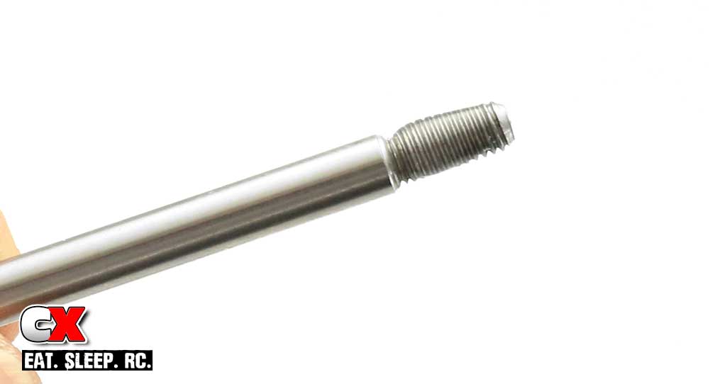
Apply a small drop of shock oil to the threaded area of the shock shaft and slowly insert into the shock. Slip the shock boot over the shaft and wrap it over the bottom shock cartridge. Thread on the shock shaft rod end and the threaded spring collar.
Step 6:
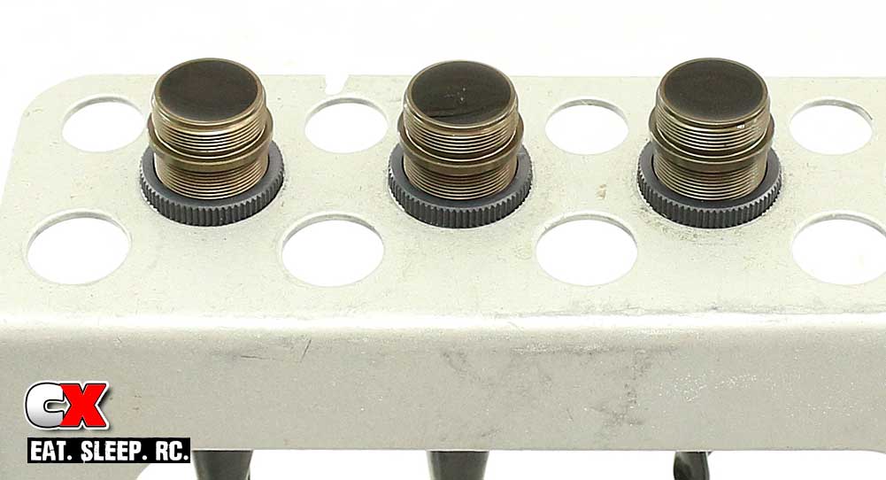
Fill the shocks with fluid; the fronts get the 550wt, the rears get 450wt. Slowly move the shock shaft up and down to remove any bubbles from under the piston. Do this a couple times and then set aside to allow all the bubbles to float to the top.
Once the bubbles are gone, add more fluid until it is even with the top of the shock body.
Step 7:
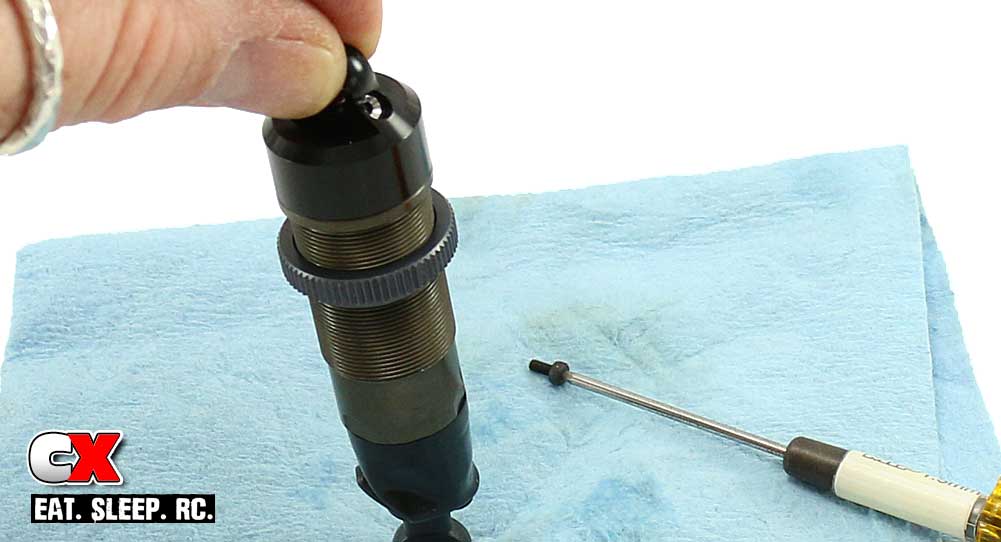
Add one or two drops of fluid into the shock cap and screw it on to the shock. Set the shock on your paper towel and slowly compress it; you will see some of the fluid exit via the bleeder hole in the cap. Once the shock is fully compressed, insert the M2x4 screw into the cap and tighten down. Clean up any excess fluid that is on the outside of the shock.
Step 8:
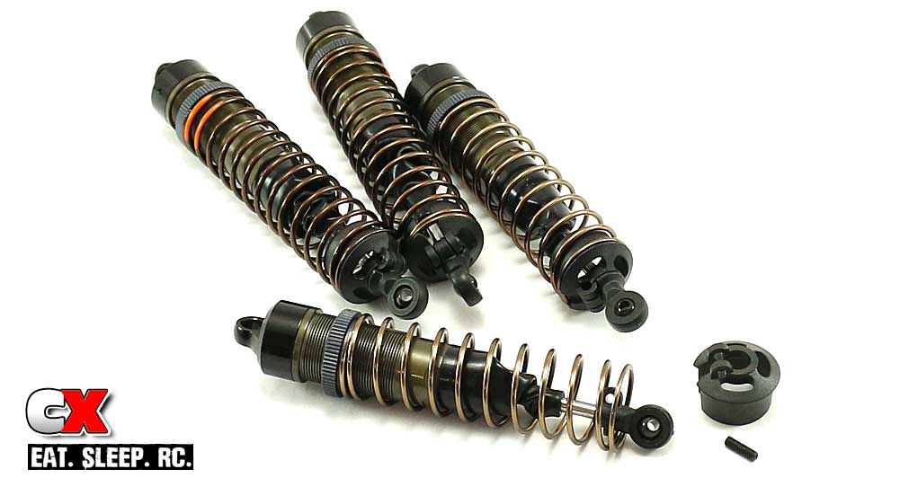
Feed the springs onto the shocks (shorter black on the front, longer orange on the rear) and secure with the lower spring cups. To prevent the spring cups from falling off, Tekno has added a M3x10 grub screw that runs through the spring cup and the hole in the lower ball cup. Great idea.
Step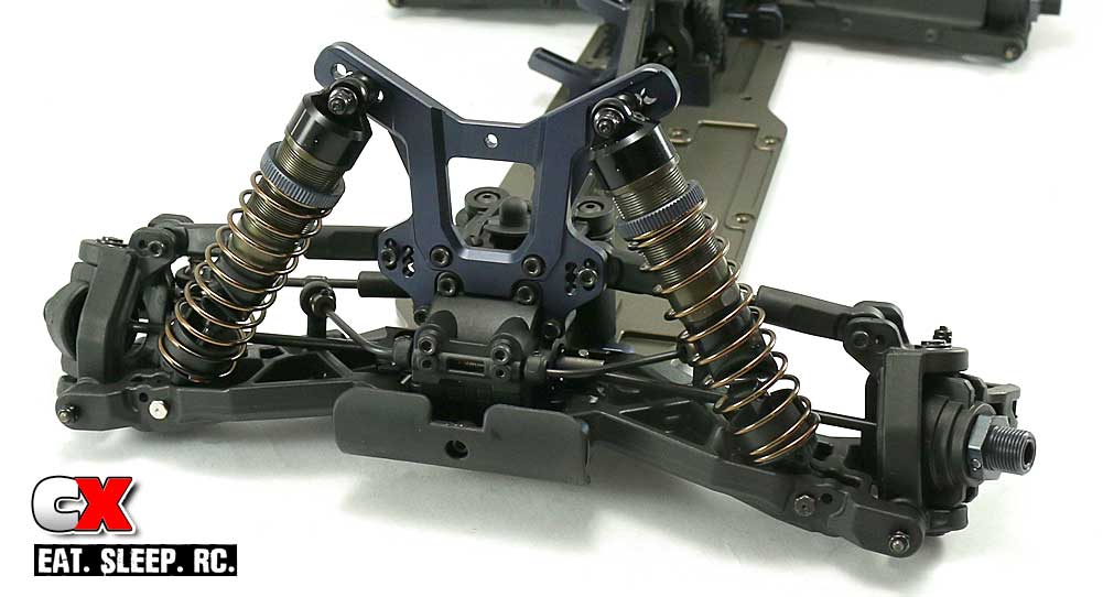 9:
9:
Attach the shorter shocks to the front of the buggy; third hole in on the tower, inside hole on the arm. Note that the left side lower mounting screw (black) has a normal thread, the right side lower mounting screw (silver) is a reverse thread.
Step 10:
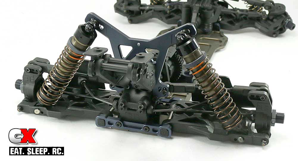
Attach the longer shocks to the rear of the buggy; second hole in on the tower, outside hole on the arm. Note that the left side lower mounting screw (silver) has a normal thread, the right side lower mounting screw (black) is a reverse thread.
Boom! It’s starting to look like a buggy! Take a second to clean up any oily areas and lets get rocking on the electronics!
Tekno RC EB48.4 E=Buggy Build – Part 6
Since the Tekno RC EB48.4 is a competition-level buggy, I get to put competition-level electronics in it! For this step we’ll be installing some gear from Futaba, ProTek RC, Tekin!
Build Notes:
• The steering servo resides at the front of the buggy, the receiver towards the back. This is great for weight distribution but, unfortunately, the servo lead isn’t long enough to reach the receiver. FYI, you’ll need an extension to make it work; it’s say a 2-3″ one is good; all I had lying around was a 8″ one. I guess it will work for now.
• Have some CA glue handy. In Step 3, you’ll need to CA some rubber o-rings to the ESC mounting plate.
• Our Tekin ESC comes without wires attached, so a soldering iron is needed. Just a heads up that you might need one if you choose a system similar to the Tekin.
Step 1:
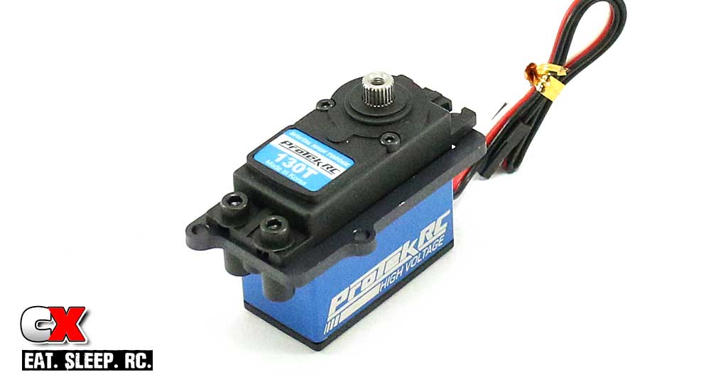
The electronics install starts off with us bolting our ProTek steering servo to an aluminum bracket. This is a little tricky (I could have used a third hand) but be patient and you’ll get it. Just pay attention to the orientation of the output shaft on the servo – I didn’t and had to do this step twice.
Step 2:
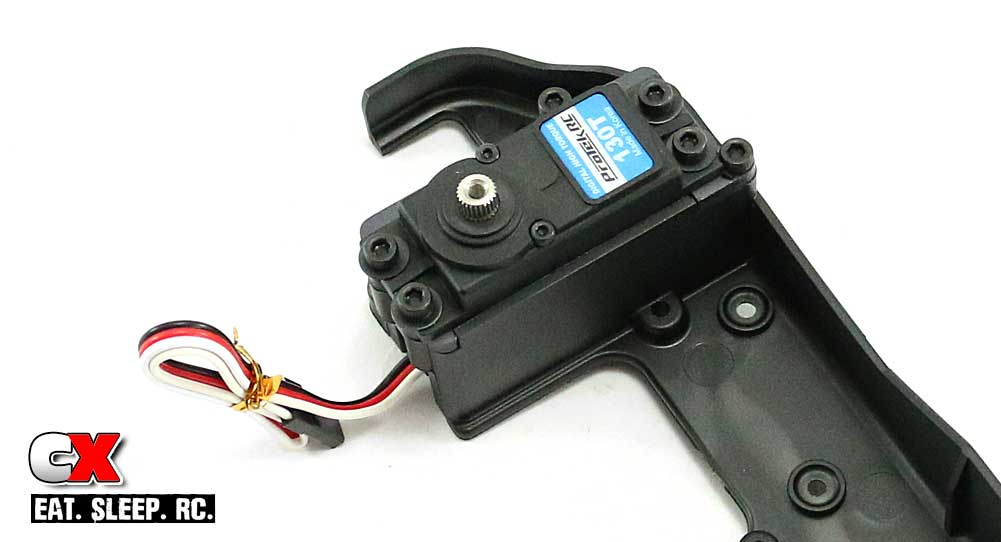
Now install the servo assembly to the plastic side guard. I have to say, this is the most securely fastened servo I’ve ever seen!
Step 3:

Tekno has added some o-rings that must be CA’ed to the bottom of the ESC mount. This cushions the ride and prevents extreme jarring of the ESC during hard landings or crashes.
Make sure you wait for the CA to dry before moving on.
Step 4:
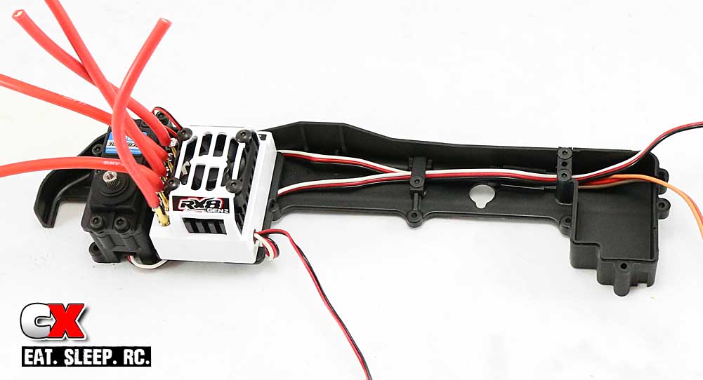
Attach the ESC plate to the chassis. I did this prior to attaching the ESC to it, making it easier to manage.
Once mounted, you can tape the ESC to the plate. Run the servo and ESC wires along the side of the guard to the receiver box. Two looms are attached to keep the wires tidy.
The only issue I had with this was the fact that my servo lead was too short and I needed an extension. Thankfully I had one handy (even if it was a bit long), so I was able to continue with the build.
Step 5:
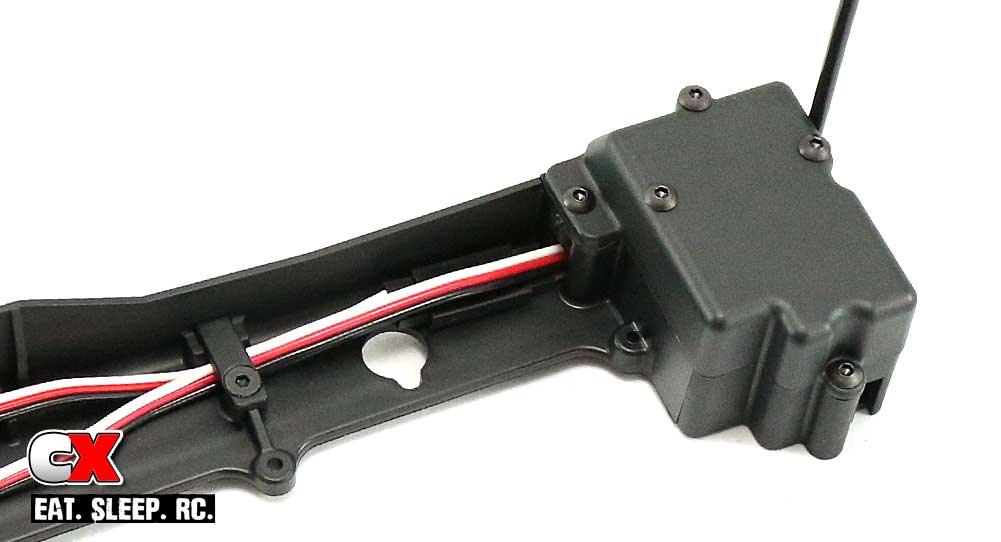
Using double-sided tape, mount the receiver inside the box, plug the leads in and feed the antenna out the side of the box and into the antenna tube. Secure the antenna tube with a M3 grub screw. Attach the lid with the M3x6 screws.
If you’re installing a transponder, you can do so to the top of the lid. I wasn’t, but I installed the screws anyway to keep them safe.
Step 6:
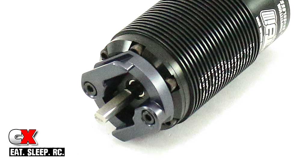
Attach the motor mount to the motor. I suggest test fitting the motor to make sure the motor wire tabs are correctly orientated.
Step 7:
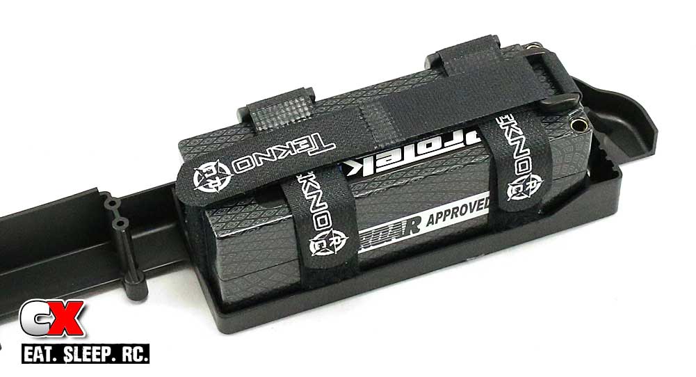
Time to install the battery straps. You can just set them up and adjust later, but a more effective way is to insert the battery and set the straps up right now. I’m impressed with this setup – there’s some major strappage here!
Step 8:
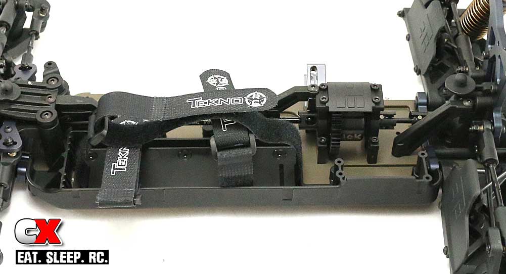
Remove the battery and attach the side rail to the chassis; six screws from the top (M4x6mm) and two from the bottom (M4x10mm). The six from the top require blue threadlocker, the two from the bottom won’t.
Note; screwing all of this together pinches the battery straps, rendering them unmoveable. If you pre-mounted the battery, you should be good to go. If not, you’ll need to loosen them up, install the battery, adjust and then re-tighten all the screws. Trust me, go back to Step 7 and do it that way. Less headaches.
Step 9:
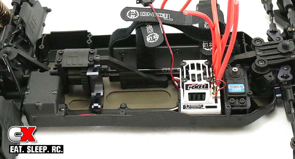
Attach the right side rail to the chassis using three M4x10 and five M3x8 screws – all from the bottom.
Step 10:
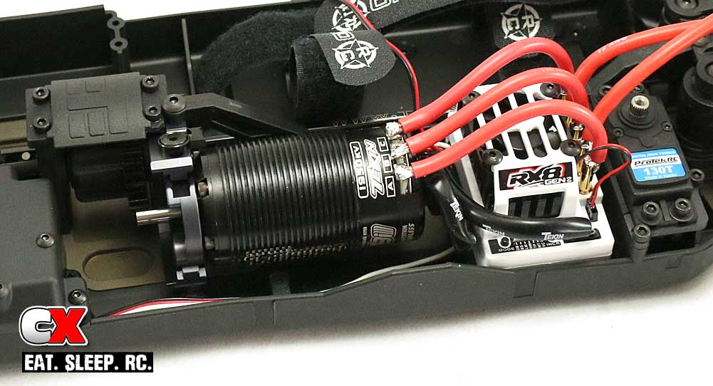
Slide the motor into the grooves in the mount and secure with the two M4x15 screws (one from the top, one from the bottom). The M4 countersunk washers allow more gripping surface for a stronger hold. Blue threadlocker is suggested as well.
Yes, I know, I don’t have a pinion on the motor yet. Well, that’s because I wasn’t quite sure what my gearing would be for my local track. I’ll be adding it later.
Step 11:
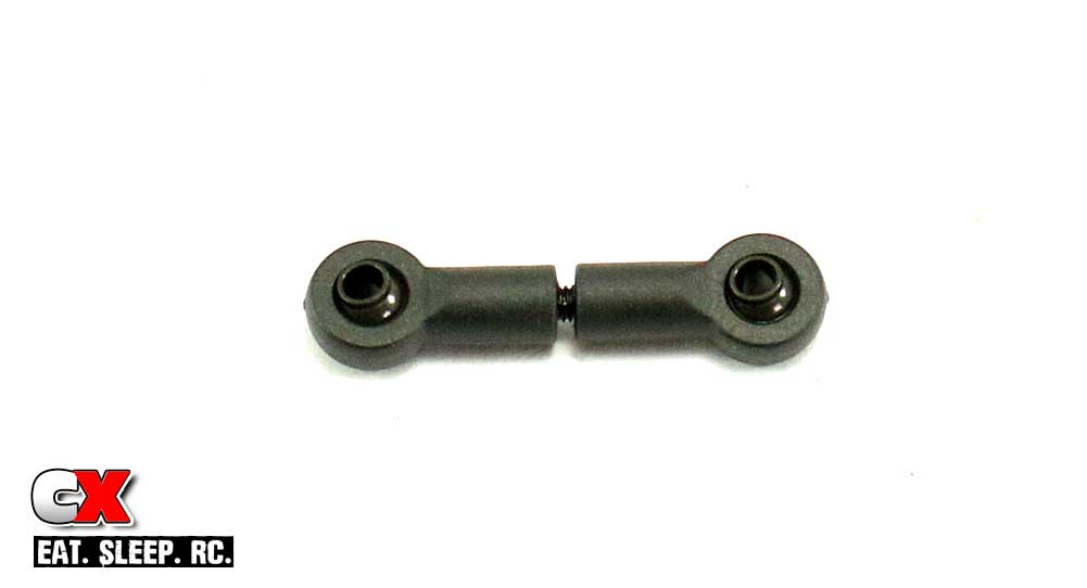
Assemble the steering link. The 1mm gap is a good starting point.
Step 12:
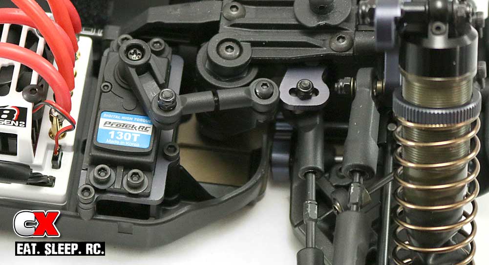
Attach the correct steering horn on your servo and use the link to connect the horn to the bellcranks.
If you’re like me, you probably can’t wait to fire this thing up and here it hum. If you do, this is also a good time to check to make sure you servo arm is correctly set (see the manual about correct servo arm positioning).
Ok, do a quick clean up and let’s head into the final step – body, wheels and tires!
Tekno RC EB48.4 E=Buggy Build – Part 7
The final step in our Tekno RC build is to attach the body, wing, wheels and tires. The kit comes with a clear body and white wing, however not wheels and tires so the choice is up to you depending on the surface you are racing on.
Build Notes:
• The instructions gives you a diagram for wing hole options; less holes, more downforce, more holes, less downforce. Before you start drilling all willy-nilly, I suggest running the wing in stock form to see how the buggy works.
Step 1:
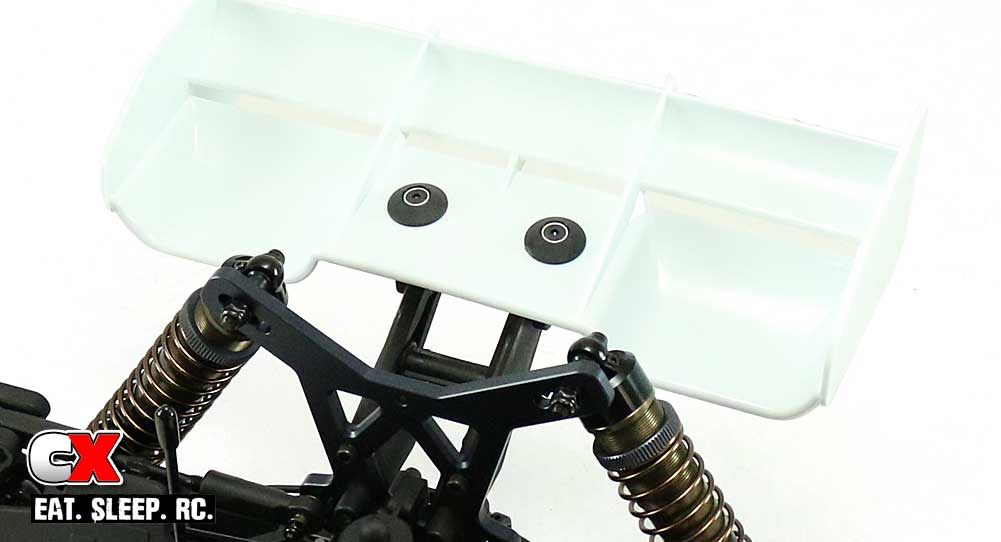
For the inital test, we’re going to run the wing as is. The manual shows the ability to swiss-cheese it up, but stock is just fine for now.
Press the M3 locknuts into the wing mounts, set the wing on top and screw together using the M3x14 screws. Don’t forget the wing buttons and silver countersunk washers. Don’t overtighten.
Step 2:
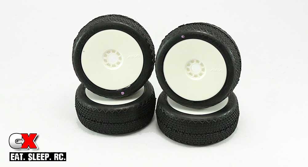
I’ll be using a set of AKA’s Typo pre-mounts on my buggy. These are molded in AKA’s clay compound for use at my local track, http://www.ocrcraceway.com.
Step 3:
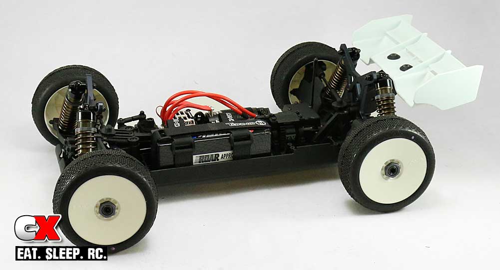
Press the tires onto the hexes and secure with the 17mm wheel nuts. Note that one side of the nut is serrated; make sure this side is towards the wheels.
Step 4:
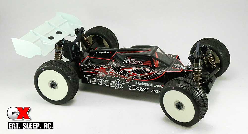
The EB48.4 with race body installed. Ya, it looks sick, right? Thanks to local painter Walter Thomas of WT Paint Designs. He did an amazing job – if you get a chance, I suggest clicking that link and checking out the rest of his work. And, his prices are very reasonable!
And that’s a wrap!
Thanks for following along with this build and if you have any questions, please don’t hesitate to ask. Stay tuned for a full review and driving video!

