

Team Associated RC10B6D Online Build
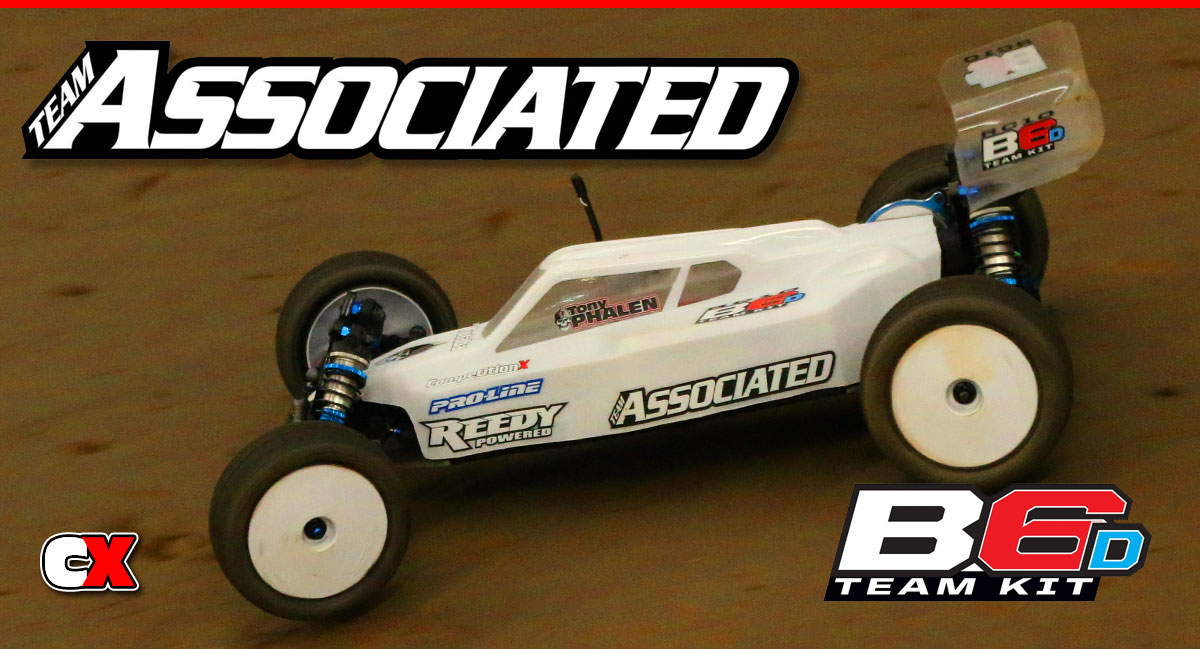
The B6D is Team Associated’s next-gen competition 2WD buggy. It’s seen some major updates over the B5 series and comes in two flavors; a carpet version (B6) and a dirt version (B6D). Both are similar in design but each has been optimized for their specific surface.
CompetitionX was lucky enough to get their hands on a B6D complete with a full Reedy setup. I’ll also be installing a Futaba receiver so I can take control with my trusty 4PX transmitter.
So grab a drink and get your tools as we take this buggy from bags to build in this detailed online assembly.
Team Associated RC10B6D Online Build – Part 1
The Team Associated B6D uses a standard dual-bellcrank steering system that rolls on high-quality bearings. A few refinements have been made to make it easier to build and smoother on the track. I like the new front bulkhead that separates the shock tower and the camber link as well as the side rails that replace the muliple molded pockets.
Build Notes:
• In Step 3, pay close attention to the direction of the steering bellcrank brace. The through-holes have a small lip on them – this lip needs to face the bearings to ensure you don’t bind the system when tightening down the screws.
• In Step 6, the manual calls out 4 10mm screws and 6 8mm screws. They’re not all marked in the manual which isn’t a big deal, but it did take me a second to think it through which screws are which. I’ve outlined it a little better.
• In Step 7, do not tighten the screws holding the servo to the mounts. There needs to be a little wiggle room until you mount the servo to the chassis – then tighten up the screws.
Step 1:
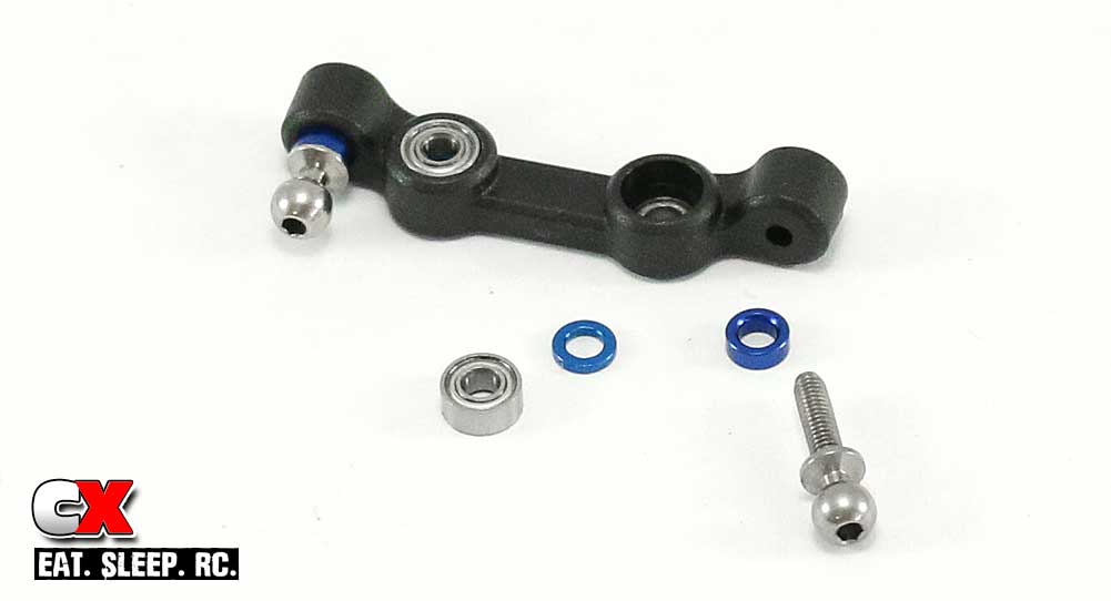
The first step is to install the bearings and ballstuds into the steering rack. Pay close attention to the orientation of the rack, both the top and the front. Press the bearings in with the blue 1mm washer in between. Install the ballstuds and include a 2mm washer.
Step 2:
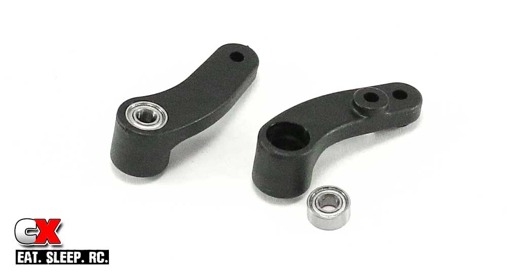
Press the bearings into both of the bellcrank arms.
Step 3:
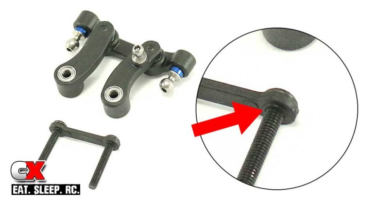
Attach the bellrank arms to the steering rack as shown (note the orientation). Slide the two 20mm screws through the steering bellcrank brace, making sure the small lip is facing down.
Step 4:
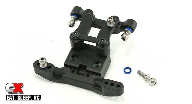
Attach the steering assembly to the front ballstud mount. Do not overtighten – you want the steering to swing freely with as little slop as possible. Insert the ballstuds into the middle hole in the ballstud mount. Don’t forget your 1mm washers.
Step 5:
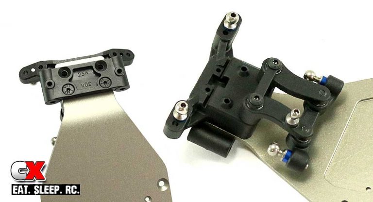
Grab the front bulkhead and note the numbers on the bottom; 25° and 30°. We want the 25° setting for the kit setup; make sure it is facing forward during assembly. Flip the chassis over and slide the two 16mm screws through the front bulkhead, then through the chassis. Flip the chassis back over and screw the 16mm screws into the steering/ballstud mount assembly.
Step 6:
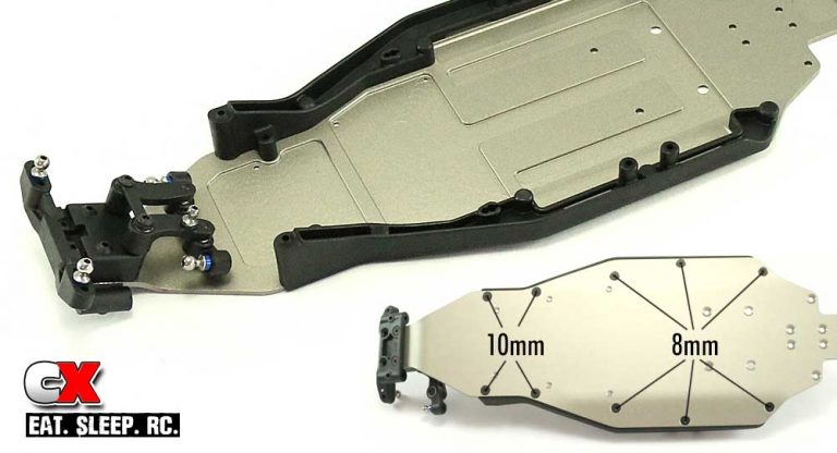
Attach the left and right side rails to the chassis. Note the screw locations for the 8mm and 10mm screws.
Step 7:
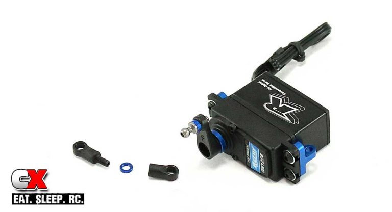
Team Associated includes four servo horns to fit a wide selection of servos. Since we’ll be using a Reedy servo, it uses a 25-spline horn, similar to a Futaba (F). Slide the servo horn ring over the Futaba horn, install the 8mm ballstud and mount to the servo. Attach the two aluminum servo mounts as well, but do not tighten them all the way down just yet. Finally, build and attach the drag link.
Step 8:
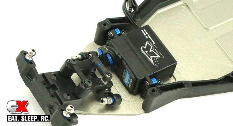
Attach the servo assembly to the chassis. Leaving the aluminum servo mounts loose allows us to space them to match the mounting holes. Once you’ve attached the servo, tighten down the four servo mount screws.
Step 9:
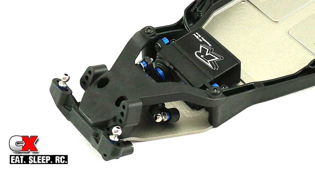
Attach the top plate to the chassis.
There you have it – the front suspension done. Time to move on to the front suspension!
Team Associated RC10B6D Online Build – Part 2
The Team Associated B6D has gone away from the gullwing front arms and now uses a flat-arm design. It still retains the caster block inserts, but replaced the axle-height shims with a much more user-friendly dual-height aluminum insert.
Build Notes:
• The only issue I found during this install step was the manual marking the caster hat bushing; it states: Top: 1mm, Bottom: 2mm. This contradicts the actual drawing though, but the correct install is to put the 2mm bushing on top.
Step 1:
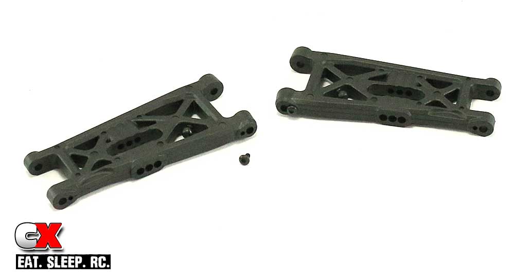
Let’s start the front suspension off easy – install the two M2x4mm screws into the suspension arms. Note the orientation.
Step 2:
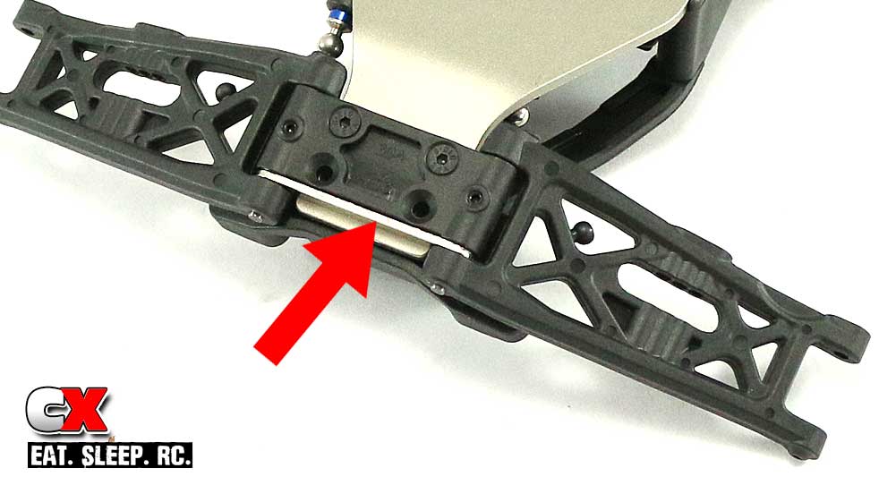
Slide one suspension arm in place, making sure you set the hinge pin brace in between the arm and bulkhead (see red arrow), then slide the hinge pin through. Do the same for the opposite side. Insert the 3mm set screws into the bulkhead to capture the hinge pin. Do not overtighten.
Step 3:
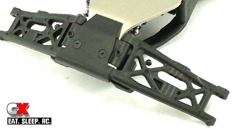
Install the front bumper.
Step 4:
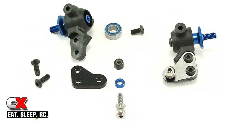
Insert a 5×10 bearing into each side of the steering block. Insert the aluminum front axle and capture it with the 6mm screw (threadlocker is suggested here). Note the orientation of the steering block.
Attach the steering block arm to the steering block, also noting its orientation. Finally, attach the 8mm ballstud and 2mm washer. Build the left and right sides.
Step 5:
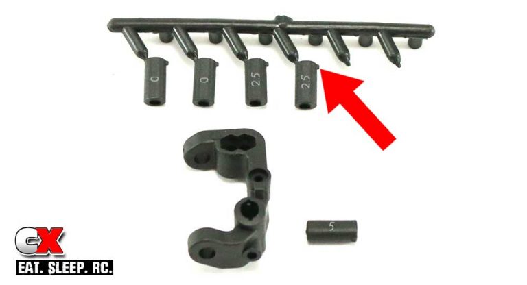
The caster block uses inserts for adjustment; there’s a 0°, 2.5° and 5° pair. Also notice the raised tab (red arrow). These key into the steering block and can be inserted either with the tab up or down to further change the caster setting. We’ll be using the 5° up (I’ve highlighted the numbers so you can see where they are on the inserts).
Step 6:
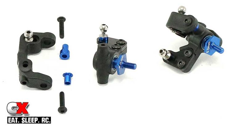
Install the 10mm ballstud into the caster block, using the inside hole. Insert the 2mm caster hat bushing (in the top) and the 1mm caster hat bushing (in the bottom) into the caster block, then slide the assembled steering arm in between and secure with the pair of 14mm screws. Build both sides.
Step 7:
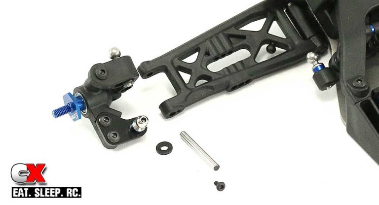
The final part of the front suspension install is to attach the assembled steering block to the suspension arms. Slide the hinge pin through the arm, the plastic caster block spacer and then the assembled steering block. Insert the M2x4mm screw to capture the hinge pin.
Before moving on, give everything a quick swing to make sure it moves freely. The next step is the first part of the rear suspension – yes, there’s two parts. Go get a drink.
Team Associated RC10B6D Online Build – Part 3
The rear suspension on the Team Associated B6D is similar to the B5M with, of course, a few changes. This is Part 1 of the rear suspension; we have to build the gearbox before final rear suspension assembly.
Build Notes:
• No build notes for this step.
Step 1:
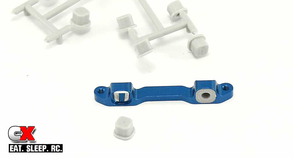
AE has included a bunch of inserts for the C mount. These blocks change the rear toe-in and anti-squat of the buggy. We’ll be starting with the 3-1 insert, the standard setting on most AE buggies. Clip these off the tree and press into the aluminum block as shown.
Step 2:
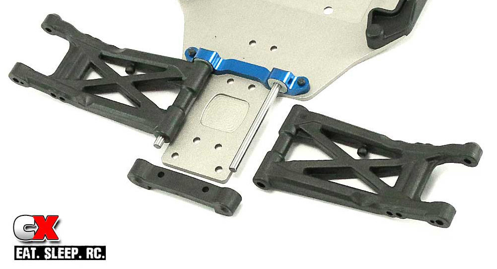
Attach the C block to the chassis; a light dip of threadlockers is suggested on these screws. Insert the hinge pins into the inserts, then slide the rear suspension arms into place. Note the orientation of the rear arms; the anti-roll bar ball should be towards the front. Slide the D arm mount into place over the hinge pins.
Step 3:
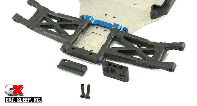
Team Associated has changed up the rear bumper and removed the gearbox brace from the tower – both wonderful fixes! Easily slide the rear bumper under the D arm mount and feed the two 16mm screws up through the holes in the bottom of the chassis. They will screw into the gearbox brace.
Step 4:
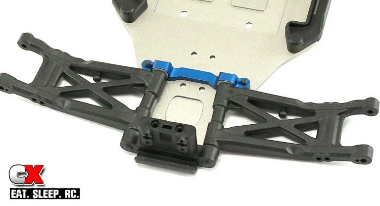
Here’s what the final assembly will look like.
Quick and easy – part 1 of the rear suspension done! Let’s build the gearbox and then it’s off to Part 2 of the rear suspension.
Team Associated RC10B6D Online Build – Part 4
The Team Associated B6D uses a 3-gear, laydown transmission. AE’s fantastic ball diff is included as is a lightweight motor plate, aluminum top shaft and their Factory Team V2 slipper clutch.
Build Notes:
• If you’ve built an AE differential before, you know how easily they go together. When it comes to assembling the two diff halves to the diff gear, I always do it a little differently than what’s shown. Either way is ok, I just prefer to do it as shown in Step 4.
[divider]
Step 1:
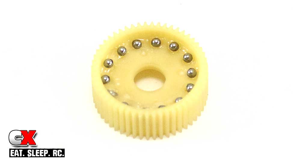
Using the clear diff lube, apply a liberal amount into all of the holes in the diff gear. I usually pour the diff balls into the gear and slide them into place in the holes; that’s just me. Feel free to use whatever method you’d like to place them.
Step 2:
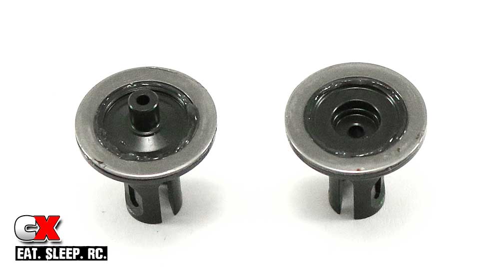
Apply a couple small dabs of clear diff lube to the outdrives, then set the diff rings into place. Rotate the rings to help spread the diff lube.
Step 3:
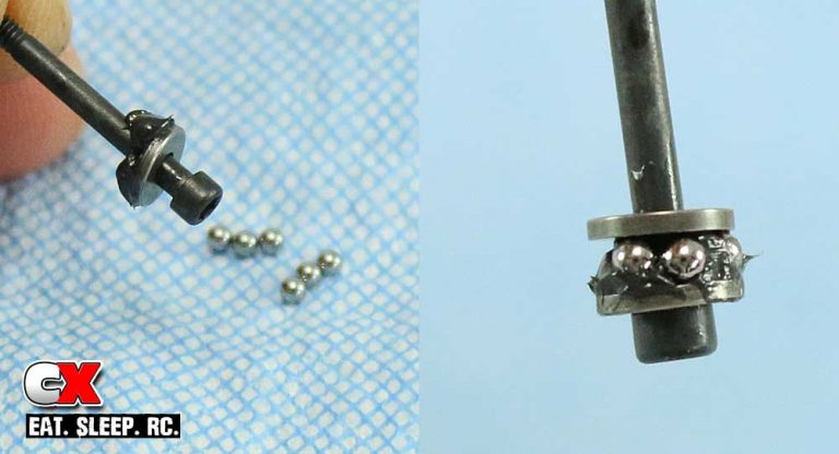
Here’s another easy way I’ve found to build the thrust assembly. Dump the thrust balls onto a clean rag or towel. Slide one of the thrust rings onto the thrust nut and apply a liberal amount of black grease as shown. Now roll the greased thrust assembly through the balls and the grease will pick them up. Drop the second thrust washer onto the assembly and press all the balls towards the screw. Wah-lah – easy peasy.
Step 4:
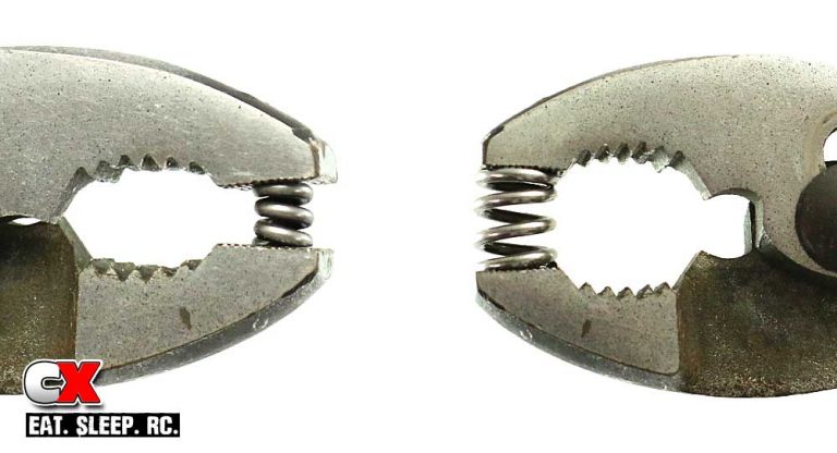
Before further assembly, pre-compress both the diff spring and slipper spring. One or two full compressions is fine.
Step 5:
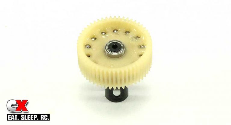
Here is where I always do things a little different than the manual; slide the two 5×8 bearings onto the male diff outdrive followed by the diff gear assembly. This makes it easier to handle in the next step.
Step 6:
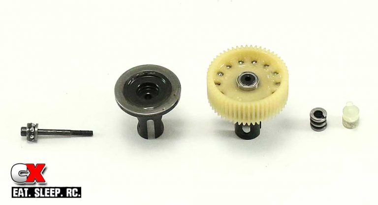
Connect the two diff outdrives together, then insert the diff thrust screw assembly through the female outdrive. Slide the diff spring and locking t-nut into the male diff outdrive and tighten down the diff screw. Follow the diff tightening instructions in the manual; tighten until you feel the diff spring bottom out, then back off 1/8 of a turn. This should be a perfect starting setting.
Step 7:
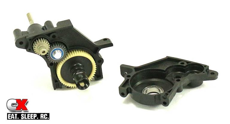
Press the 5×10 and 10×15 bearings into both gearbox cases, making sure the blue shield is facing out. Press two more 5×10 bearings into the idler gear followed by the idler gear shaft. Insert the aluminum top shaft, idler gear assembly and diff assembly into the gearbox case, making sure the diff adjustment nut is facing the spur gear (or, in this picture, facing out of the case half). Press the two case halves together and secure with the 14mm screws.
Step 8:
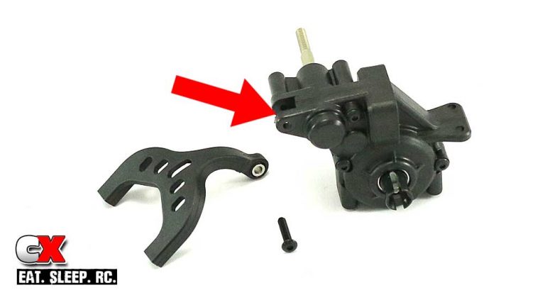
Press the pivot ball into the chassis brace arm and attach the assembly to the gearbox.
Step 9:
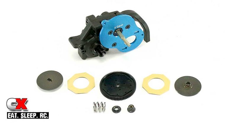
Attached the aluminum motor plate to the gearbox. Press the slipper pads into the spur gear grooves; they should stay put. Install the inner hub, assembled spur gear, outer hub, spring, spring adapter and secure it all with the M4 locknut. Stock setting is the nut flush with the end of the top shaft, but I suggest double-checking this on the track before your first run.
Laydown 3-gear transmission done! Make sure it spins freely, although I’m not sure how it wouldn’t if you followed this awesome guide. Let’s get it installed in Part 2 of the rear suspension build.
Team Associated RC10B6D Online Build – Part 5
Part 2 of the Team Associated B6D rear suspension build has us attaching the gearbox and assembling the rear hubs. The rear hubs still use inserts to control rear toe and camber link locations. I’m also really liking the new rear ballstud mount.
Build Notes:
• In Step 4, you will need to press the aluminum hub link nut and plastic link insert into the rear hub. The aluminum part only fits in one side of the hub, so don’t worry about getting it mixed up.
Step 1:
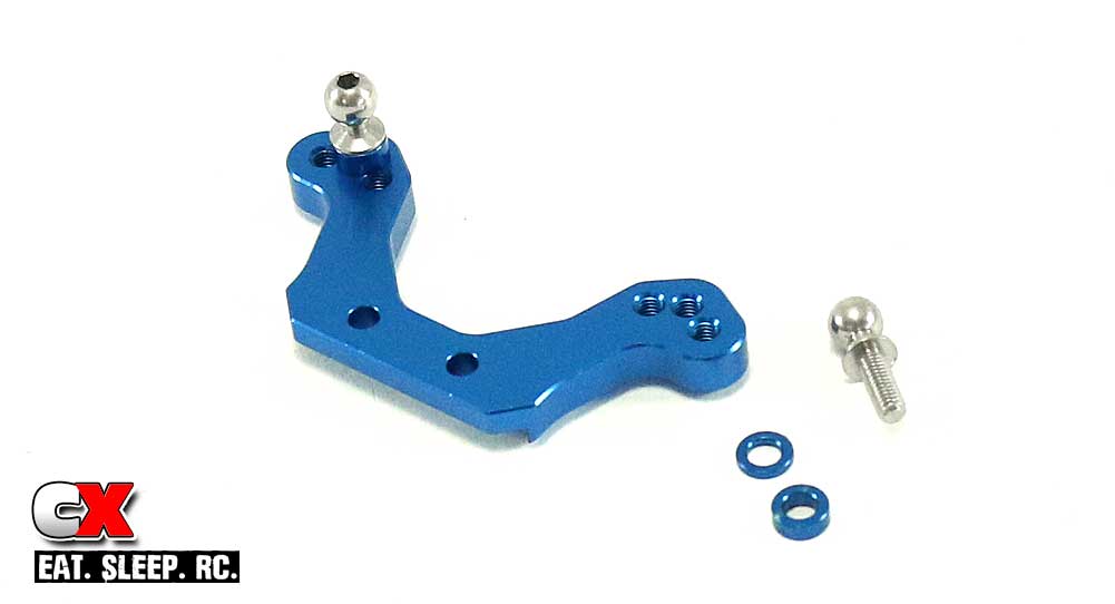
The rear ballstud mount now gets sandwiched between the gearbox brace and gearbox … a much better design in my opinion. Start by inserting the 8mm ballstuds into the center hole, using one 1mm and one 2mm shim under each ballstud.
Step 2:
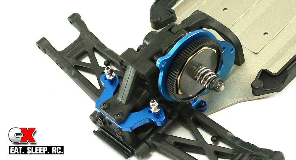
Press the aluminum ballstud mount onto the gearbox brace, then set the gearbox into place. Secure with the two 14mm screws up top and the 10mm and 12mm screws underneath.
Step 3:
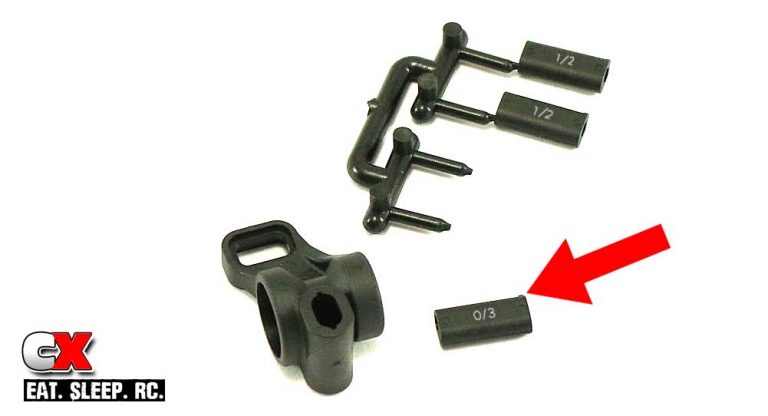
Like the front, the rear hubs use inserts with tabs to alter the performance. We’ll be using the 0/3 block with the tab up (I’ve highlighted the numbers so you can see where they are). Press a 0/3 insert (tab up) into each rear hub.
Step 4:
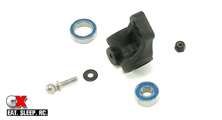
Press the aluminum hub link nut and plastic link insert into the rear hub with the 3-holes to the top (it has 5 holes in it). Slide the 3×8 washer over the 10mm ballstud and feed it through the hub using the top/center hole. Secure it with the M3 locknut. Now press a 6×13 and 10×15 bearing into each hub.
Step 5:
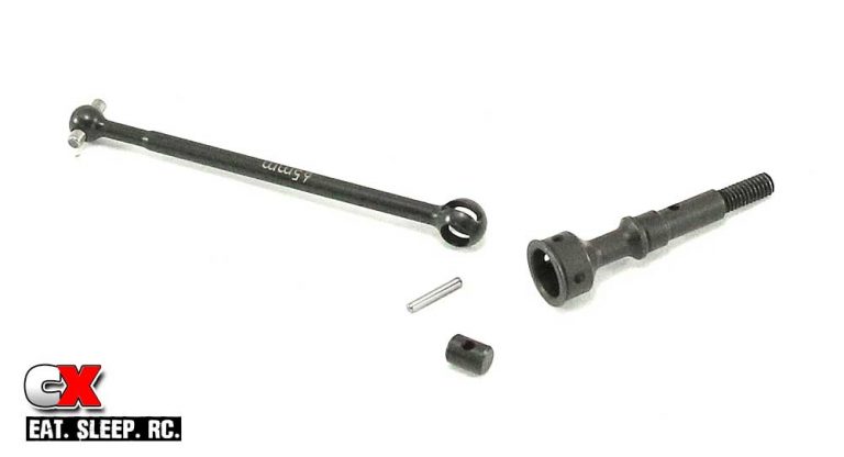
Assemble two CVA drive bones. Slide the coupler into the ball at the end of the bone, then slide that assembly into the CVA axle. Line up the holes and insert the hex pin through the axle and coupler.
Step 6:
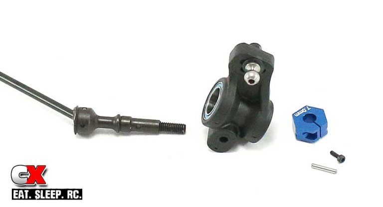
Feed the axle assembly through the rear hub assembly, making sure the pin stays centered in the CVA. Once through, slide another hex pin through the axle, then slide the 7.0mm aluminum wheel hex over the hex pin. Use the 1.6x5mm pin to clamp the hex.
Step 7:
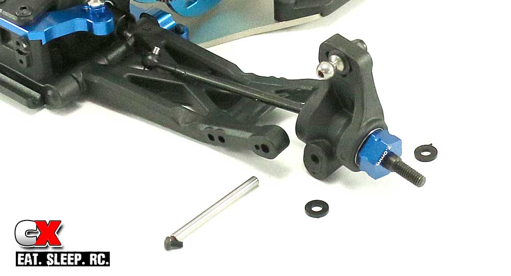
Slide the outer hinge pin though the rear suspension arm, though one rear hub spacer, the assembly rear hub and the second hub spacer. Secure the hinge pin with the M2x4mm screw. Complete both sides.
Rear suspension is now done … time to build the turnbuckles and shocks!
Team Associated RC10B6D Online Build – Part 6
The Team Associated B6D has been upgraded to carbon fiber status, giving us both front and rear woven shock towers. These really look great and certainly give the buggy a more racer look!
Build Notes:
• The upside of the carbon fiber shock towers is they look awesome and are super rigid – the downside is that they are exposed to crashes that could delaminate them. I sealed the edges of my towers with super glue to help protect them – you can see our carbon fiber prepping article here: How to Prep Your Carbon Fiber Parts.
Step 1:
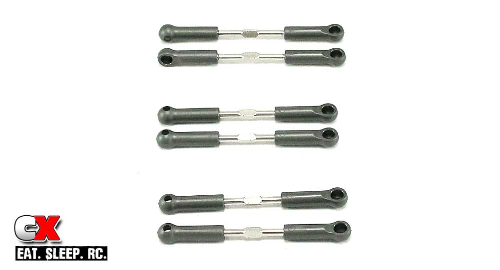
Build the three sets of turnbuckles per the manual; the lengths are all about spot on. Yes, my turnbuckles aren’t quite built correctly but they are correct on the car. Shush.
Step 2:
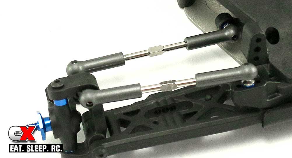
Attach the left and right steering and camber turnbuckles, making sure the little ‘notch’ is facing the same way. This makes adjustment side-to-side much easier.
Step 3:
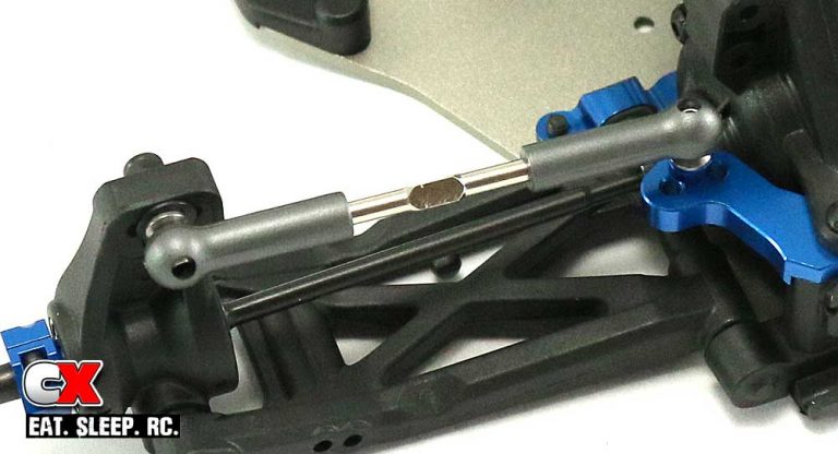
Same with the rear camber links. Make sure you insert the CVA bone into the outdrive before popping the links on.
Step 4:
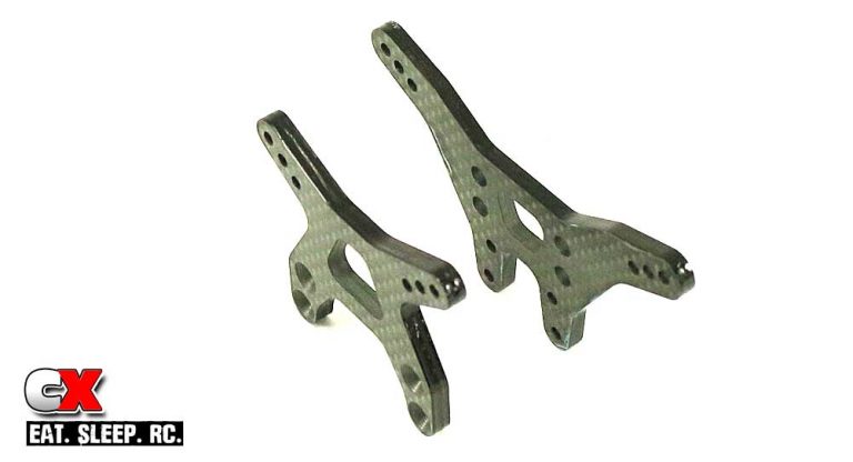
I sealed both the front and rear shock towers prior to installation. It only takes about 5 minutes and the final result looks much better.
Step 5:
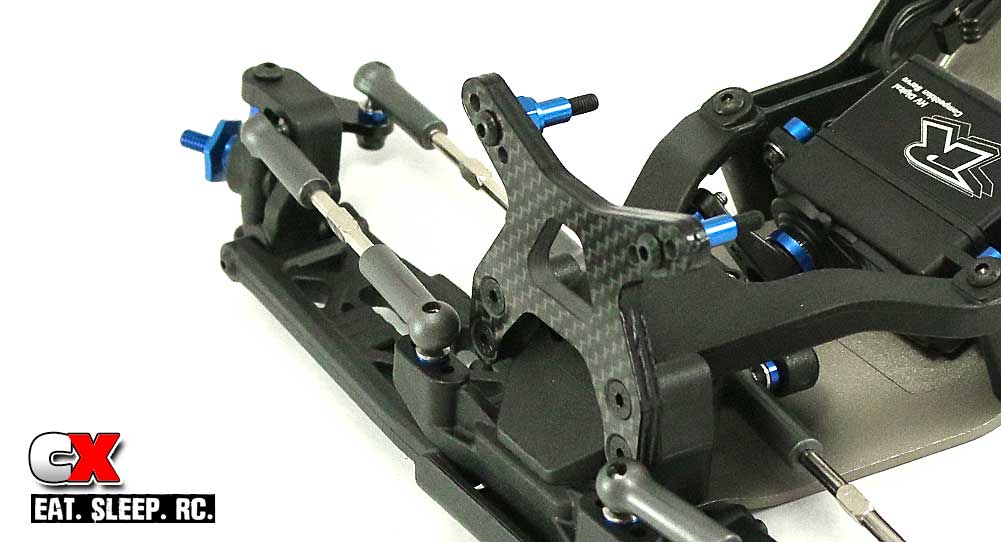
Install the shock mounting hardware in the middle hole of the tower (note orientation), then attach the tower to the front bulkhead.
Step 6:
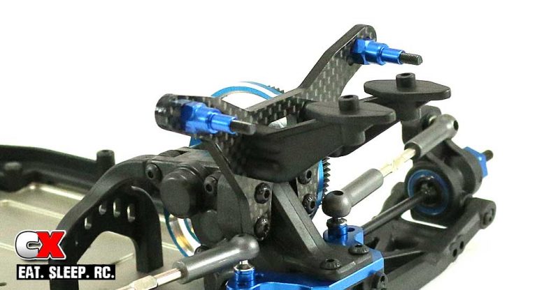
Install the shock mounting hardware and wing mounts to the rear tower, then attach the tower to the gearbox.
Six easy steps, now it’s on to the shocks.
Team Associated RC10B6D Online Build – Part 7
The V2 12mm Big Bore shocks are used on the Team Associated B6D. These have always been some of my favorite shocks both in build and smooth operation. Time to get building!
Build Notes:
• Building shocks can be a messy experience, so I suggest having a clean space with some sort of covering in case things get chaotic. I would also suggest having some sort of shock stand available to set them aside during building.
Step 1:
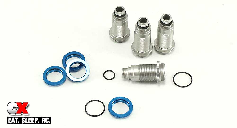
When it comes time to build shocks, I always assemble the o-rings first. If you wait further down the road, you can sometimes get oil on the o-rings which makes them 100x harder to install, especially in the collars. Dry is better, trust me on this. With that, install a large o-ring in the threaded collar and top of the shock; install the smaller o-ring over the bottom of the shock.
Step 2:
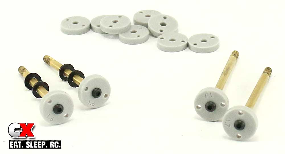
Well would you look at that, non-white shock pistons. It’s the little things, but this has to be one of my favorite upgrades – I can actually read the numbers on the pistons without having to Sharpie them! Ok, back to the build. Attach the 1.6 pistons to the front (short) shock shafts, and the 1.7 pistons to the rear (long) shock shafts. Add two .030 spacers to each front shaft.
Step 3:
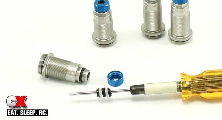
Assemble the lower shock cartridges in this order: V2 shock hat bushing, clear X-ring, V2 shock spacer, clear X-ring and another V2 shock hat bushing. Make sure the hat bushings are assembled as shown. A drop of shock oil will help the parts slide into the shock body easier. Screw on a blue shock bottom cap.
Step 4:
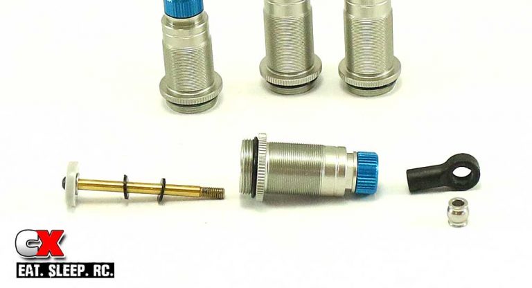
Take your shock shafts and insert them into the shock bodies; short shafts – short bodies, long shafts – long bodies. A drop of shock oil on the threads will help the shaft slide through the body easier. Press the pivot balls into four long shock eyelets and then screw the eyelets onto the shock shaft.
Step 5:
Fill all four shock with oil to the top. Slowly slide the shaft up and down to release any air from under the piston, then refill to the top again. Let them sit until there are no more air bubbles in the oil.
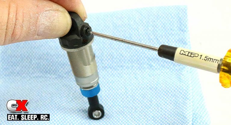
Using the M2x4mm screw, pre-drill the bleeder hole in all four shock caps. Place a drop of oil in the cap and screw it onto the shock. Slowly compress the shock, allowing any overflow oil to seep out of the bleeder hole. Once fully compressed, insert the M2x4mm screw. Wipe any excess oil off the shocks.
Step 6:
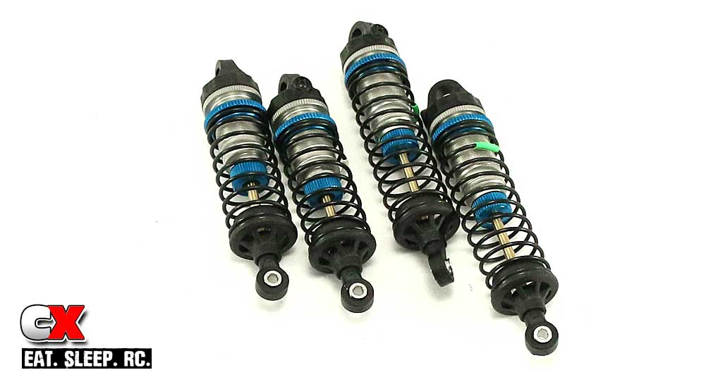
Screw the threaded collars onto the shocks, setting them at the kit specified 4mm (front) and 2mm (rear). Slide the springs on (white-front, green-rear) followed by the 5mm spring cups to the bottom of the shocks.
Step 7:
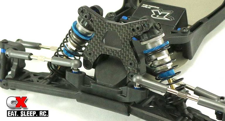
Attach the front shocks, outside hole on the arm.
Step 8:
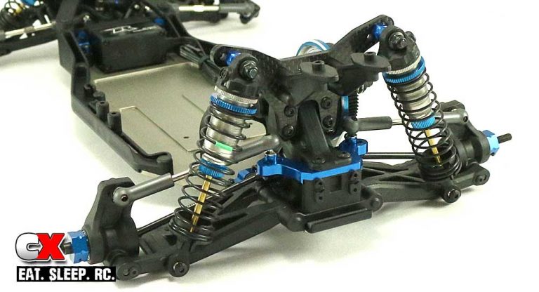
Attach the rear shocks, inside hole on the arm.
The V2 Big Bores have now been installed. On to the final step – the electronics.
Team Associated RC10B6D Online Build – Part 8
The final part of our Team Associated B6D build is installing the electronics. The B6D doesn’t have a sectioned chassis area anymore, so installing the ESC and receiver is much easier than it was before. We’ll be equipping our B6D with a full compliment of Reedy products!
Build Notes:
• There is still a channel that runs down the middle of the chassis for the brushless sensor wire, but to help keep it in place, I added a small strip of double-sided tape. This isn’t needed if you set your ESC right in the middle of the chassis, but seeing as I swapped the location of the ESC and receiver (per the manual), I needed a way to keep the wire in place.
Step 1:
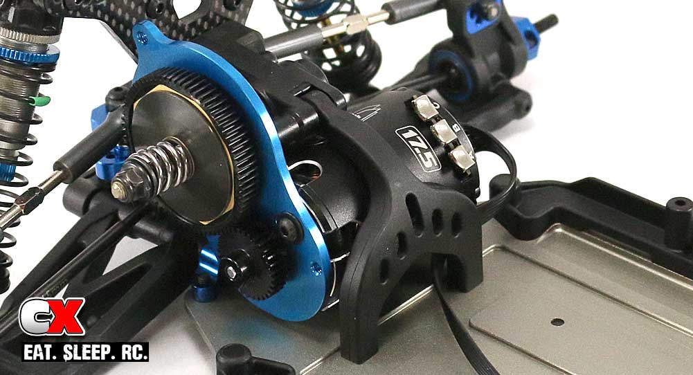
Install the motor. I would suggest attaching the sensor wire at this time as well and feeding in down the center of the chassis. Go ahead and install the pinion gear too.
Step 2:
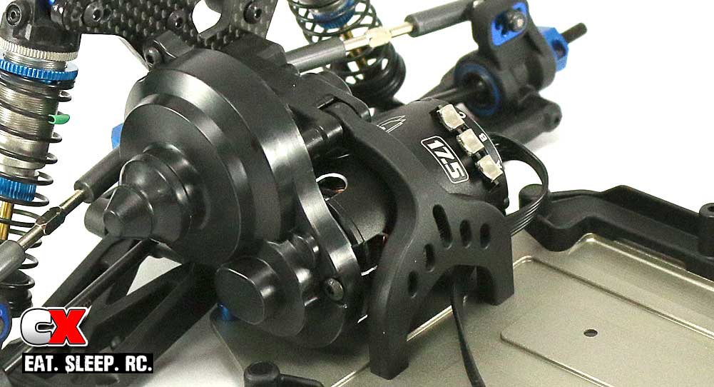
Attach the gear cover and ‘belt cover cap’. Belt cover cap … interesting.
Step 3:
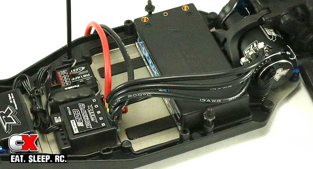
Install the receiver and ESC and tidy up any wiring you have. I opted to swap the location of the ESC and receiver (per the manual) for a couple reasons, the biggest was to keep the ESC motor wires off to the side.
Attach the foam battery pads to the chassis, then place your battery in the chassis. Install the battery strap screws until the shoulder is level with the top of the battery.
Step 4:
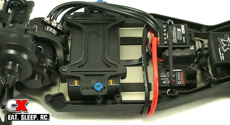
Set the battery strap in place (using the manual-specified second hole, then shift the battery forward until it is centered in the strap. Remove the strap and attach the rear battery stops. Re-install the battery strap and secure with the baby-thumbscrews.
I did leave out the body, wing and wheels/tires installation – those should be easy enough to figure out. I wanted to get the meat of the car done.
And with that, we’ve completed the build of the Team Associated B6D.

