
Team Associated TC7 Online Build
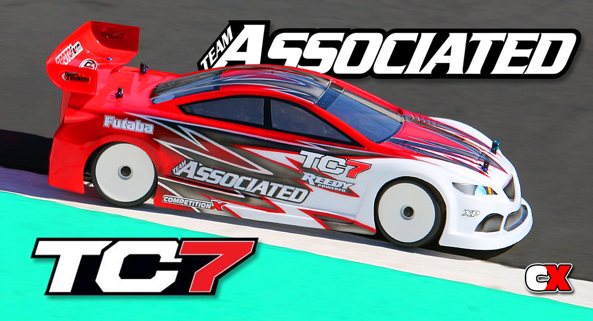
The TC7 is Team Associated’s latest asphalt blazer, and we got our hands on one to do a full online build. Included in this build will be a full set of Reedy electronics, a Futaba radio system and LRP tires … yes, I said LRP. Topping off the build is a Protoform Mazda6 GX body painted by the World-famous Larry Genova.
Aside from a few bumps, the build went together great. I got a few inside tips from the TC7’s designer and good friend, Bob Stellflue, so you’ll want to check out the build to see these tweaks.
Team Associated TC7 Online Build – Part 1
I’m going to kick off our TC7 build with the shocks. Team Associated has included a set of FOX shocks with the Genuine Kashima Coating, so you know they’re going to be silky smooth and super consistent! I’m not a fan of shock building so I’m always glad to get this out of the way when I’m pumped about building a kit. Let’s get started.
Build Notes:
• Building shocks can be a bit messy. Make sure you have a clean work area and some towels handy to clean up any spilled fluids.
• I’ll be filling up the shocks with the included fluid in Step 7 and it’s recommended that you have some sort of shock building station, or at least something suitable to hold them up while the bubbles rise from the oil. I’ve listed a few shock stations at the end of the post that will work just fine.
Step 1:
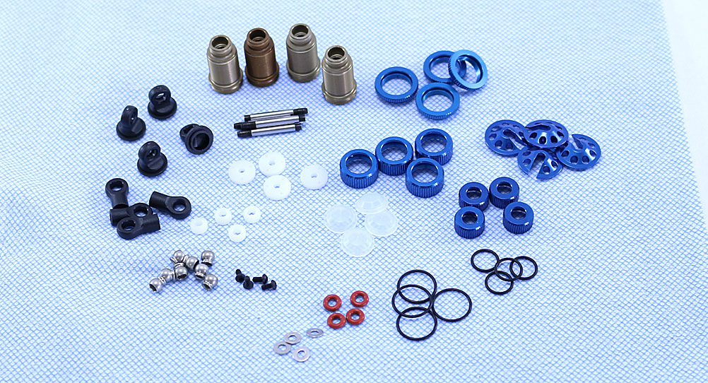
Before building, I like to lay out all my parts to make sure I have everything. It also makes it easier to build when all the plastic parts are cut off the trees and parts like the pistons have been trimmed and cleane up. The blue paper towel makes it a little easier to see the white and clear parts in the photo.
Step 2:
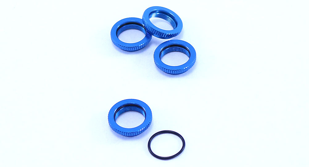
I also like to install the o-rings into the shock collars first. This makes the o-rings easier to handle, especially if you have shock fluid on your fingers. Go ahead and build all 4.
Step 3:
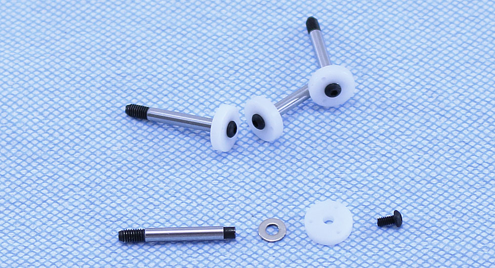
Per the instructions, I’ll be using the 3-hole pistons. Assemble as shown, making sure to use a tiny bit of blue threadlocker on the button head screw to ensure it doesn’t back out.
Step 4:
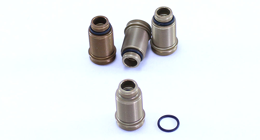
Slip the smaller o-ring over the bottom of the Kashima Coated FOX shocks.
Step 5:
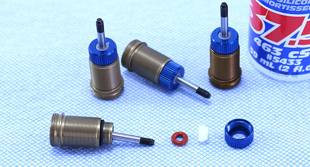
Insert the shock shaft assembly into the shock body, apply a small drop of shock oil to the threads on the shaft and install the lower seal parts. Make sure the lower shaft bushing has the lip pointing away from the shock body. Screw on the lower cap and tighten down. Move the shaft up and down and be amazed at how buttery these shocks are.
Step 6:
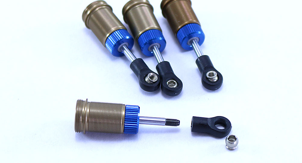
Install the shock eyelet and pivot ball on the end of each shock.
Step 7:
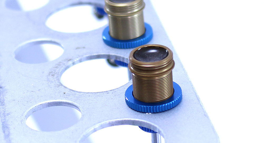
Screw on the shock collar about half way up on each shock. Fill each shock up to the top with fluid, then slowly move the shaft up and down to release any bubbles from under the piston. Set the filled shock into your shock station (you do have some sort of shock-building station, don’t you?) and let sit for a few minutes until all the bubbles have disappeared. You can see the fine bubbles still floating to the top in the picture.
Step 8:
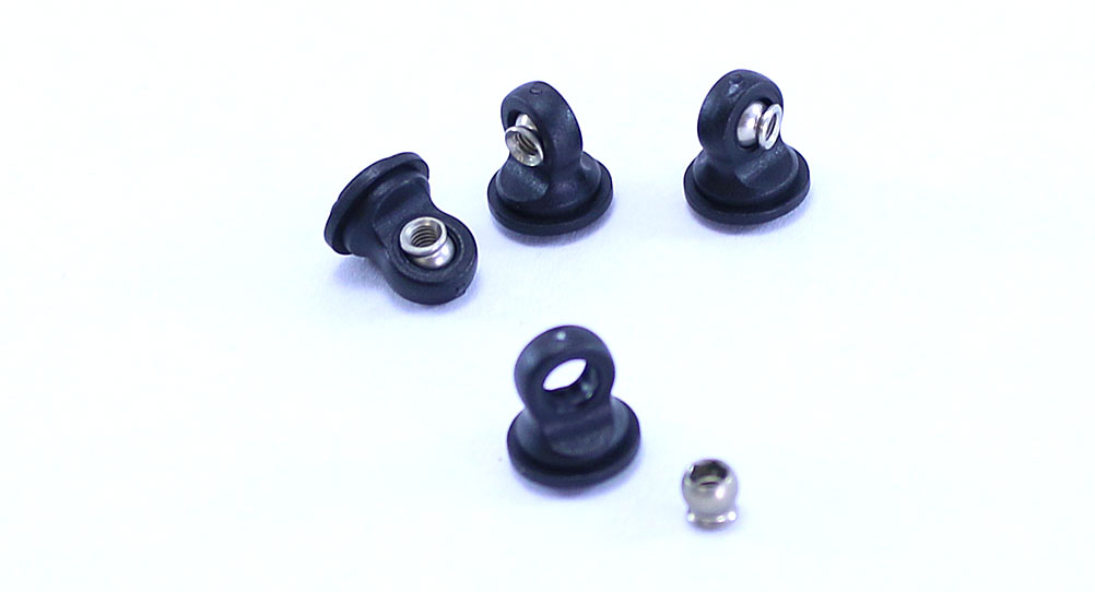
Pop a pivot ball into each of the plastic shock caps.
Step 9:
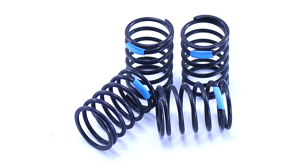
The TC7 uses blue springs on all four corners. Slide the blue shrink wrap onto the springs and use a heat source to shrink them in place. Funny, every touring car since the TC3 has come with blue springs.
Step 10:
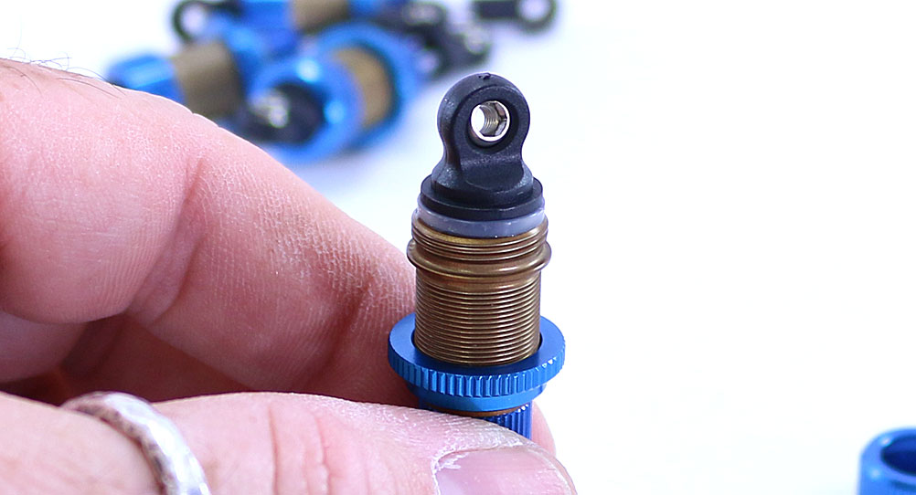
Place the clear bladder onto the top of the shock – if done right, this should displace a little oil and sit neatly on top of the shock just like the picture. Set the shock cap assembly on top of the bladder and then screw on the aluminum shock cap retainer. Do this slowly so you don’t dislodge the bladder. Tighten all the way down.
To make sure you’ve built them correctly, slowly move the shock shaft up into the body – it should bottom out on (or be close) to the lower shock cap. If it stops early, you have too much oil in the shock and will need to redo this step.
Step 11:
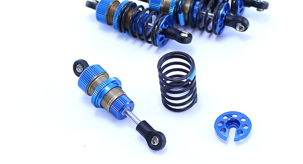
Slide the spring on followed by the lower spring retainer.
Step 12:
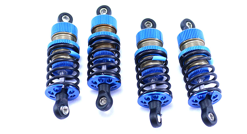
There you have it – 4 beautiful Kashima coated FOX shocks, all ready to install on your TC7. We’re not quite ready for them yet, so set them aside and let’s move on to the differentials.
Team Associated TC7 Online Build – Part 2
Part 2 of the Team Associated TC7 build revolves around the differentials. The front end uses a locked diff, or spool, while the rear uses a fluid-filled gear diff. This is pretty much the standard in touring car racing now, so let’s quit talking and get right to it!
Build Notes:
• Pay special attention to the cam settings when you build both diffs. They need to match up on the left and right.
Step 1:
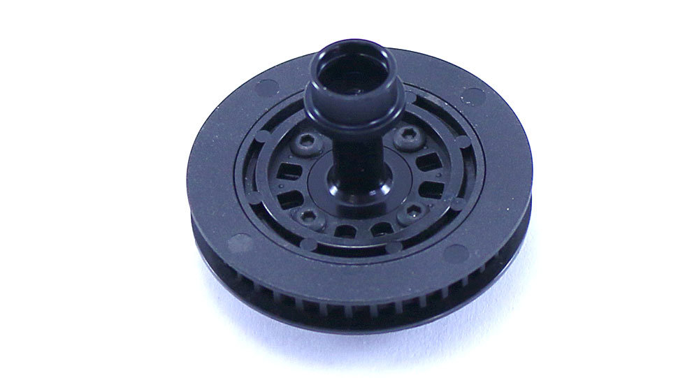
Per the manual, I’m going to work on the front spool first. Start off by gluing the outer ring to the front pulley, then attach the spool hub. I would suggest a small dab of blue threadlocker to make sure those screws stay in place.
Step 2:
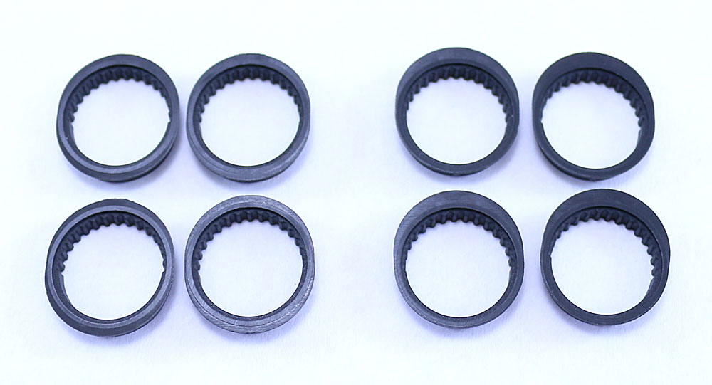
I’ve lined the 8 cam holders out so you can see them a little better. The 4 on the left are for the Mid-Low and Mid-High settings; the 4 on the right are for the Low and High settings. I’ll be using the 4 Mid-Low ones.
Step 3:
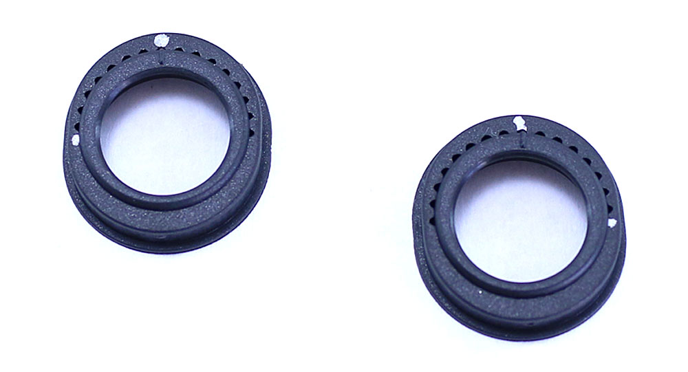
The manual suggests the cam position at location 8, so I’ve counted out 8 spots and pressed the two pieces together. To keep things straight, I put a small silver Sharpie mark at my starting point as well as location 8. This helps me orientate the sides when it’s time to install.
Step 4:
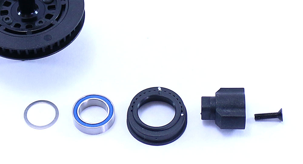
The next step is to install the shim, bearing, cam/bearing holder assembly and plastic outdrive. Slide them onto the spool assembly and capture with the M2.5x10mm screw. Don’t forget your small dab of threadlocker. An added tip is to orientate both outdrives the same prior to installation. This helps when it comes time to key the driveshafts to them.
Step 5:
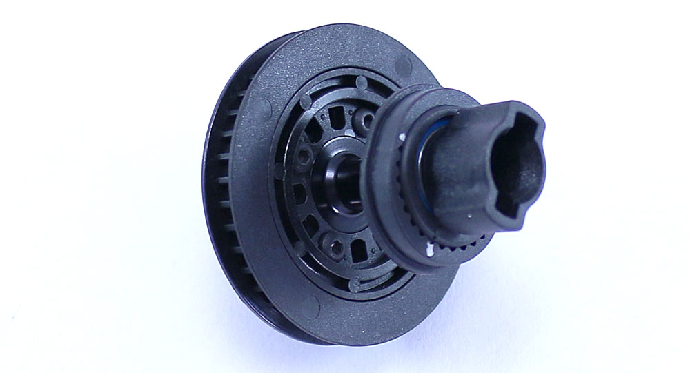
Here’s a picture of the completed install from Step 4. Set the spool aside.
Step 6:
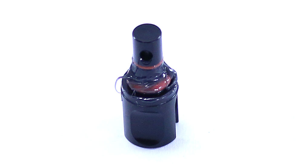
Moving on to the rear diff, let’s start by sliding both the larger o-ring onto the outdrive followed by the smaller o-ring. Note that the smaller o-ring fits into the groove just below the pin hole in the outdrive. Apply a liberal amount of black grease to the area as shown.
Step 7:
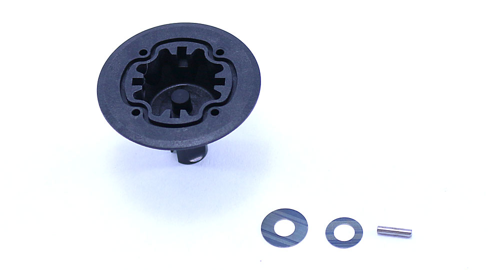
Slide the outdrive assembly into the gear case, making sure the outdrive slips all the way in. Insert one large and one small shim, then feed the diff pin into the hole of the outdrive shaft. Make sure the diff pin is centered in the opening.
Step 8:
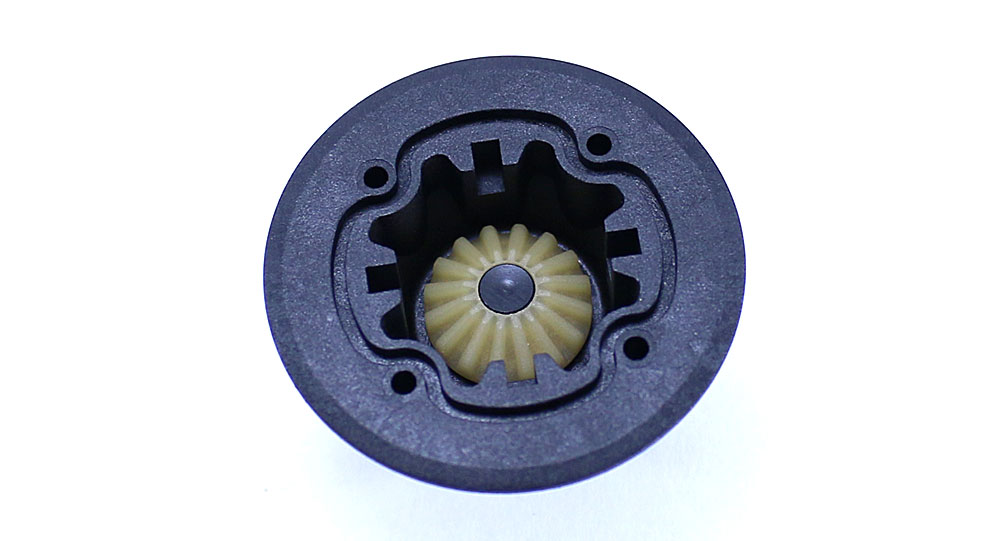
Install the sun gear, keying the backside of the gear to the pin. Note the outdrive is flush with the top of the sun gear.
Step 9:
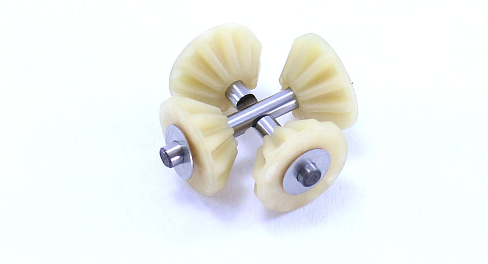
Build a pair of planetary gears assemblies as shown, keying the notches in the diff pins to each other.
Step 10:
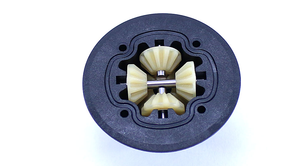
Slide the planetary gear assemblies into the diff housing as shown, spinning the outdrive to make sure all the gears seat correctly. This is also a good time to install the diff gasket as well.
Step 11:
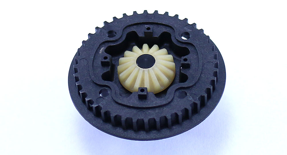
Using Steps 6-8, assemble the pulley side of the diff.
Step 12:
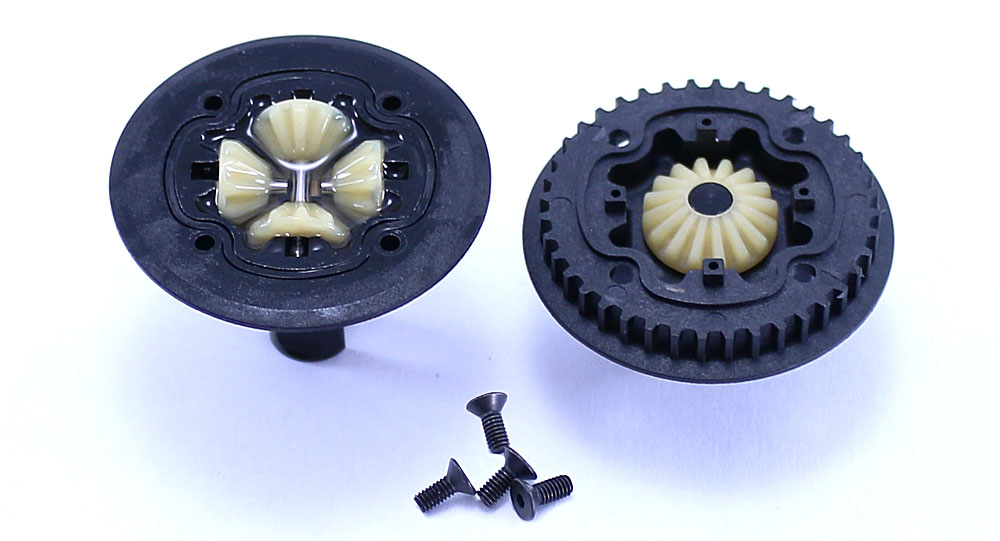
Fill the diff housing up with the 3000wt diff fluid until it’s just above the cross pins. Carefully flip and mate the two diff halves and screw together using the 2.5x6mm screws. Do not overtighten these screws; you just want them snug. Spin the outdrives to make sure everything feels silky smooth in the diff.
Step 13:

Like the front, install the diff shim, bearing and cam assembly. Note the assembly and it’s #7 position – you’ll see I marked it with the silver Sharpie for reference.
Step 14:
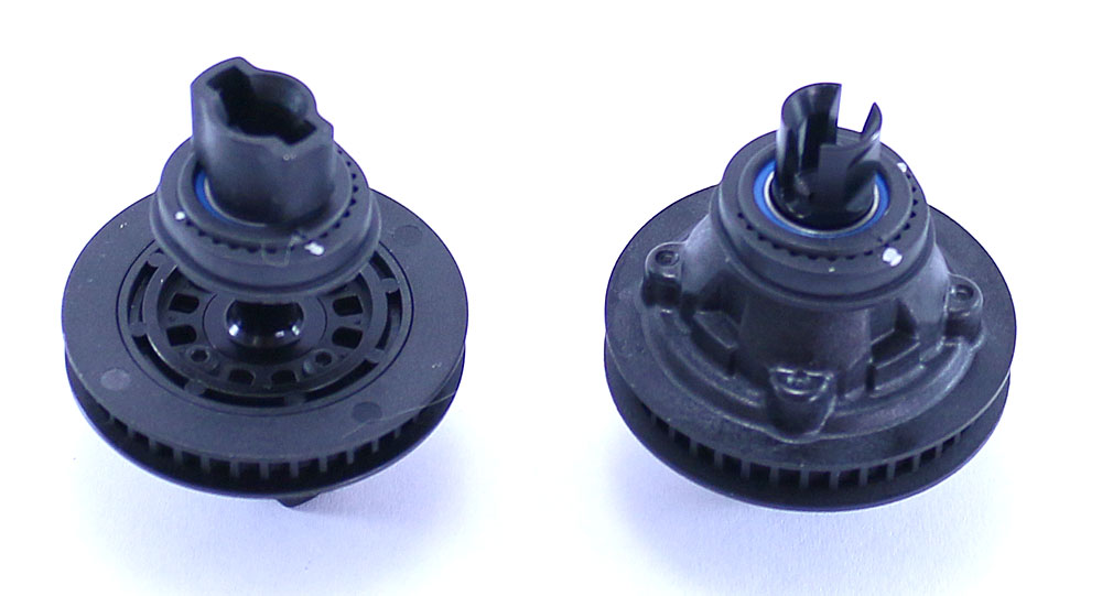
And there you go – an assembled front spool and rear gear differential ready to be installed. Set them aside. Great job!
Team Associated TC7 Online Build – Part 3
The next step in our Team Associated TC7 build is the suspension. This suspension is similar to the TC6.2, using separate hinge pin blocks and inserts to control things like anti-squat and toe. It also uses a unique shock mounting system that makes removing the shocks quick and easy. Ok, on to the suspension build.
Build Notes:
• My manual states to use a #3 and #1 insert on both the front and the rear suspension blocks. This put the hinge pins at a wierd angle so, after making a call over to Team Associated, I was informed that the manual was incorrect. The front should use #3 inserts front and back while the rear uses #1 inserts front and back. I’ll reiterate this in the steps below. I’m sure this will be fixed in future manuals so yours may already be correct.
• The manual also has building the turnbuckles incorrectly. The front and rear camber links should have matching, flat eyelets on both ends while the steering links should have opposite eyelets. Check Step 1 to see the proper building of the turnbuckles.
Step 1:
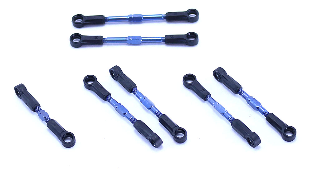
The first step is to build the turnbuckles. Shown are the drag link, the front and rear camber links and steering links. You should note that, as I stated in the Build Notes, both the camber and steering links are shown incorrect in the manual. Use the picture above and the build notes to make sure you get them right. After building them, I suggest keeping the front and rear camber links separate so you don’t mix them up.
Step 2:
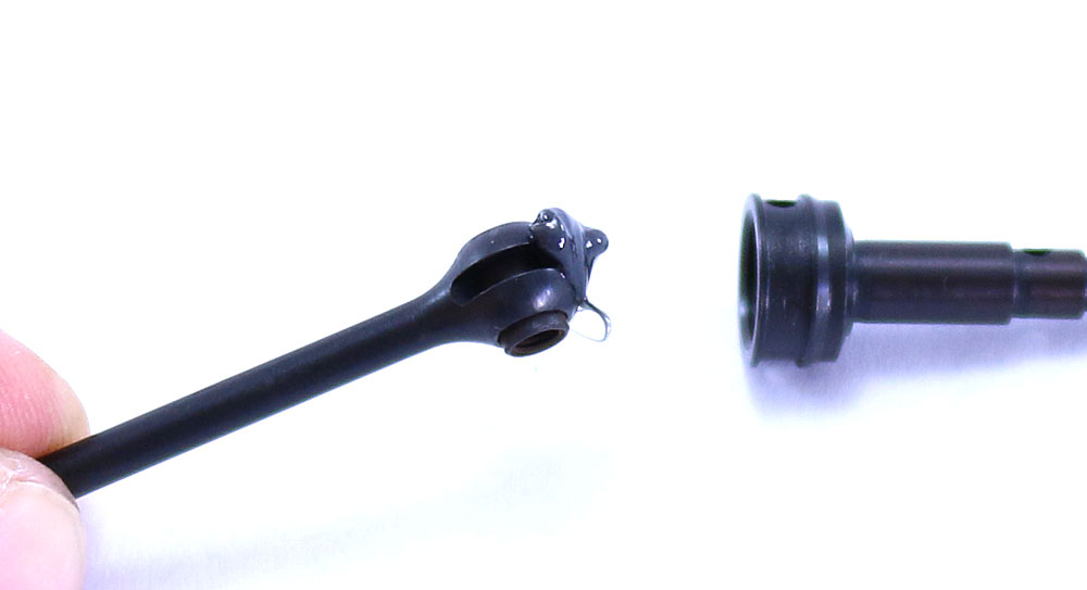
The CVAs are next. Insert the CVA barrel into the bone as shown and liberally coat the end with black grease. Insert it into the CVA axle and slide the cross pin though to connect everything.
Step 3:
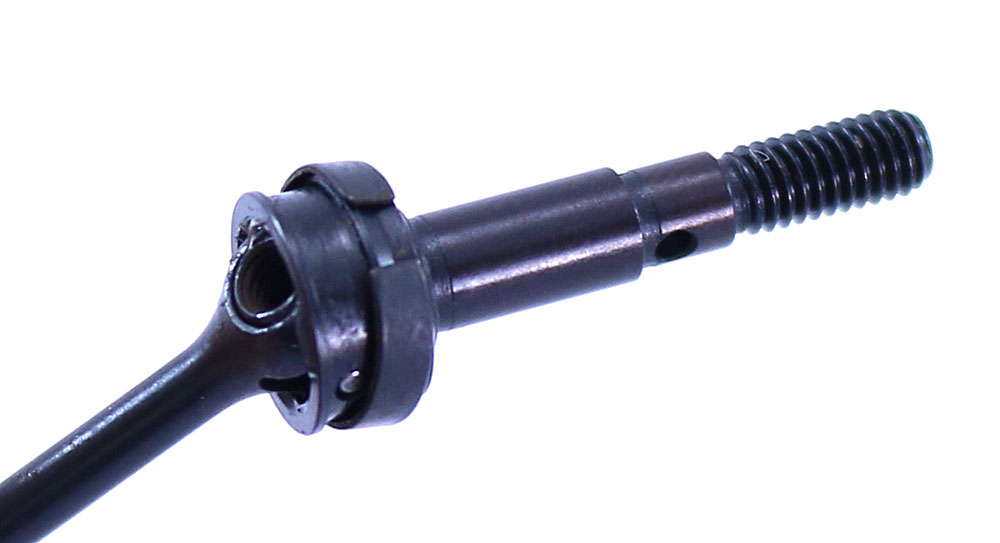
Slide the retaining clip up and into the groove in the axle as shown. Make sure the ‘gap’ in the clip is not located where the cross pin is.
Step 4:
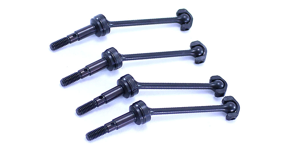
Slide the CVA blade onto the ‘bone’ end of the axle. Your 4 axles should look like this.
Step 5:
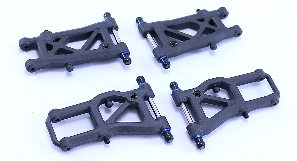
Before attaching the arm mounts, lets jump ahead and build the suspension arms first. Insert the drop screws and shock mounting set screws as shown followed by the hinge pin, spacers and hinge pin balls. A little dab of black grease will help keep the hinge pin balls in place. Pay attention to the orientation of the left and right suspension arms.
Step 6:
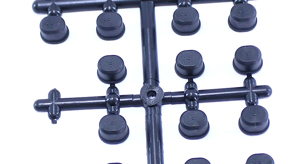
Now find the tree of arm mount inserts and remove four 1-dot inserts and four 3-dot inserts. For clarification (as stated in the Build Notes), we’ll be using the 3-dot inserts up front and the 1-dot inserts in the rear.
Step 7:
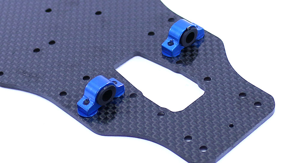
Press the 3-dot inserts into the ‘B’ arm mounts, making sure the 3-dots are facing in towards the center of the chassis. Now attach the arm mount assemblies to the chassis, using a pair of .5mm shims under each mount (1 per screw).
Step 8:
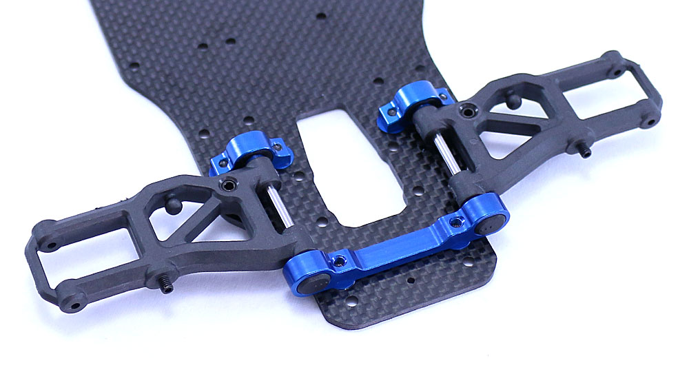
Press the other two 3-dot inserts into the ‘A’ arm mount, making sure the 3-dots are facing towards the center of the chassis. Slip your assembled front suspension arms into place and capture with the ‘A’ arm mount. When attaching, make sure you use a pair of .5mm shims under the ‘A’ arm mount (1 per screw). Move the suspension arms a bit to make sure they swing freely.
Step 9:
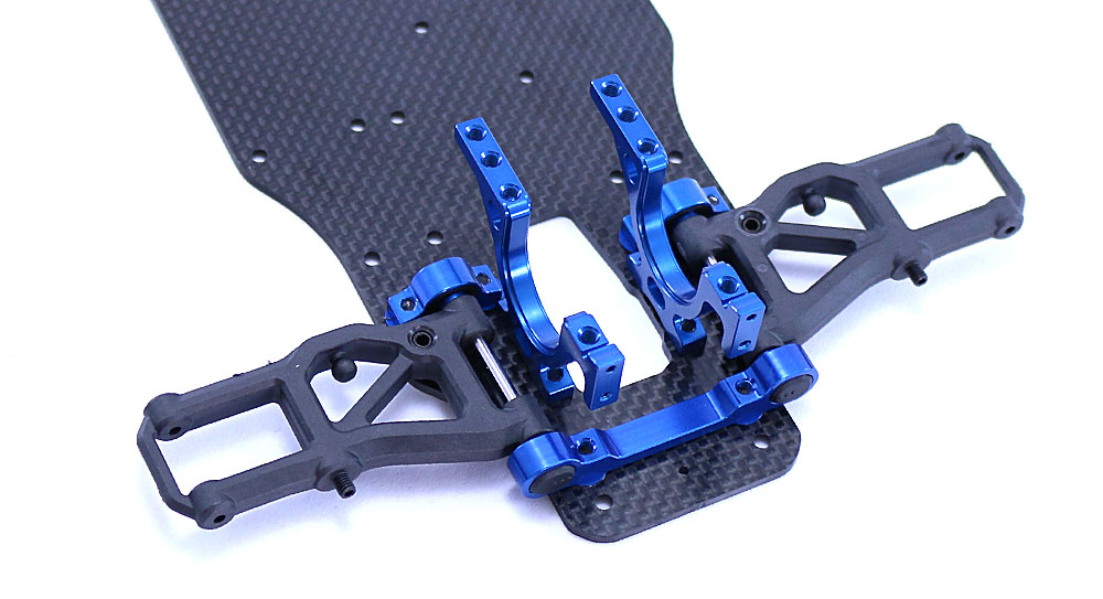
Attach the bulkheads to the chassis. These will work on the left or right as well as the front or back, just make sure you have them orientated correctly as shown. A dab of blue threadlocker is suggested here.
Step 10:
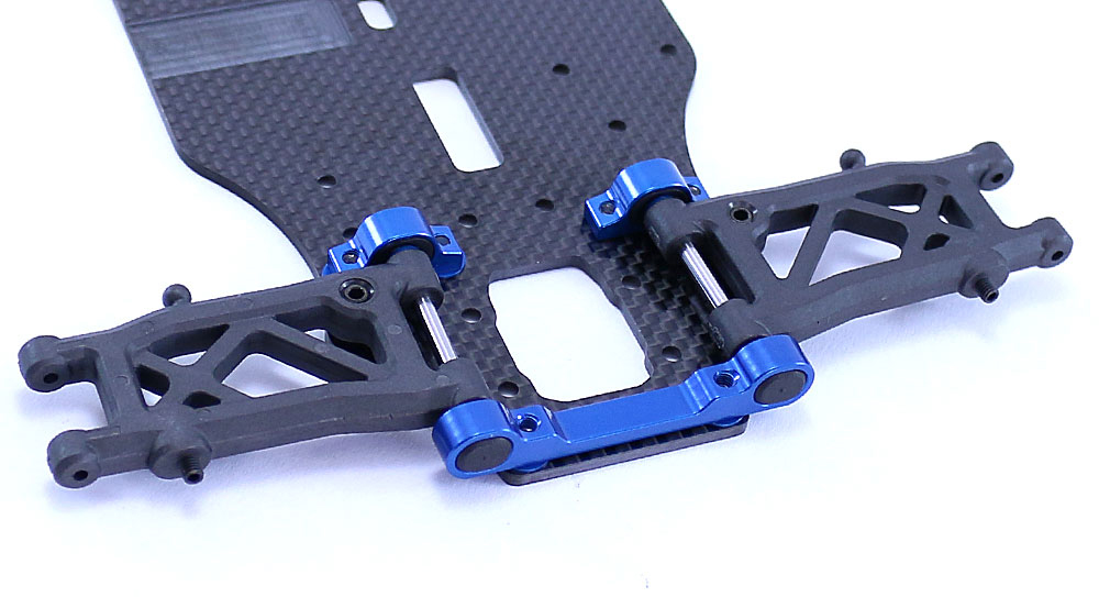
Use the same steps to attach the rear suspension arms. Note that the only difference will be that we will be using the 1-dot inserts on BOTH the ‘C’ and ‘D’ arm mounts. Don’t forget the .5mm shims. Once attached, move the suspension arms a bit to make sure they move freely.
Step 11:
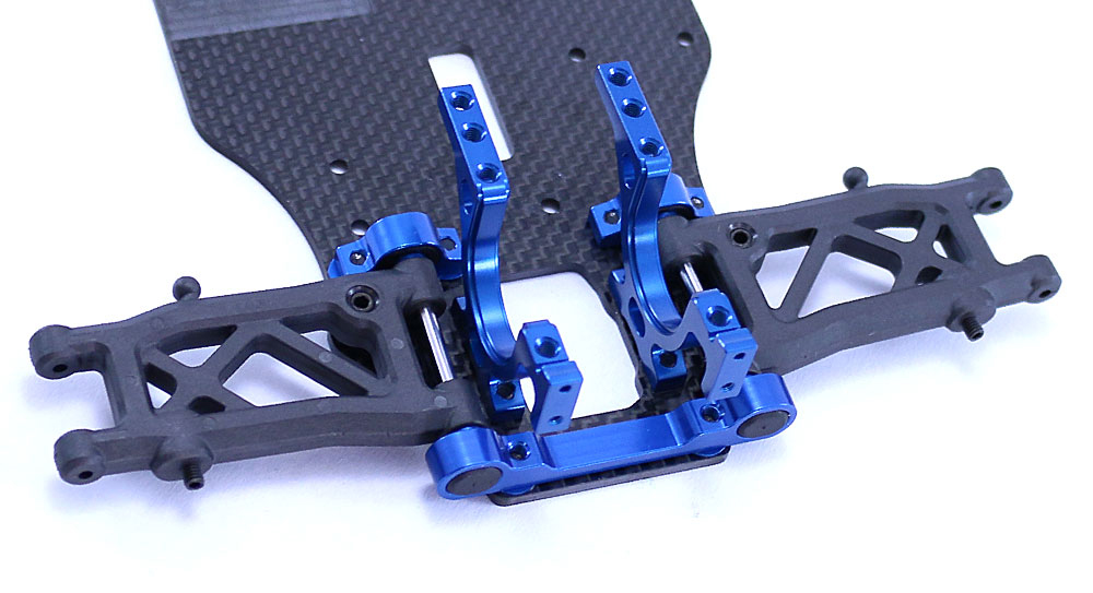
Attach the rear bulkhead in a similar fashion as you did the fronts.
Great job! Next up will be the Top Deck and Center Bulkhead.
Team Associated TC7 Online Build – Part 4
In this step I’ll be installing the one-piece center bulkhead, spur gear and belts. I’ll also be installing the front and rear differentials as well as the shock towers. A lot of steps coming up, but everything goes together quite easily.
Build Notes:
• Everything goes together well with this step. No special notes to share.
Step 1:
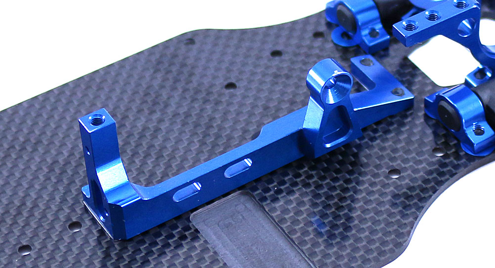
The first order of business is to attach the one-piece center bulkhead. Blue threadlocker suggested here.
Step 2:
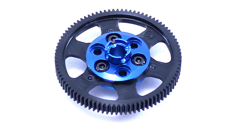
Next, assemble the spur gear. Use a small dab of blue threadlocker to ensure the screws stay put.
Step 3:
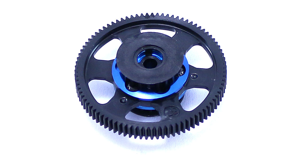
Slip a 20T pulley on each side of the spur gear assembly. Press until you feel them ‘lock’ into place.
Step 4:
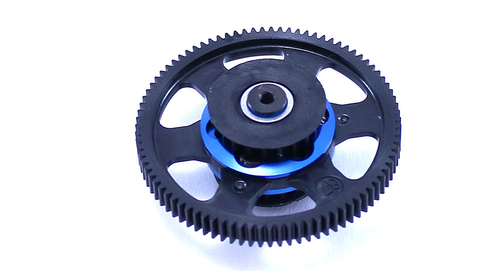
Press a 4×8 bearing into each diff pulley, then slide the gear shaft through and secure with the 6mm screw. A light dab of blue threadlocker is suggested here.
Step 5:
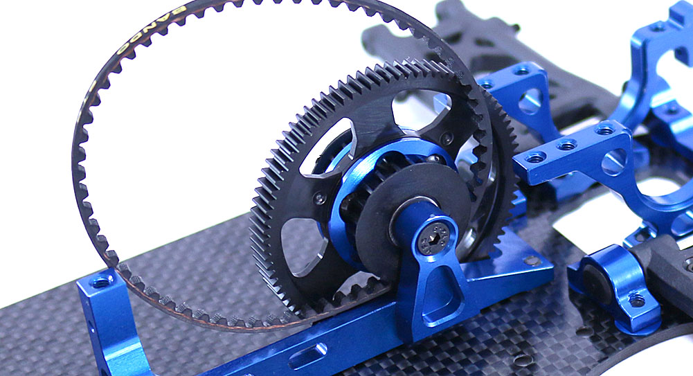
Ring the rear belt round the spur gear assembly and attach to the center bulkhead. Yes, only one screw (10mm) on one side holds this pulley in place, so I suggest some blue threadlocker to keep this baby in place.
Step 6:
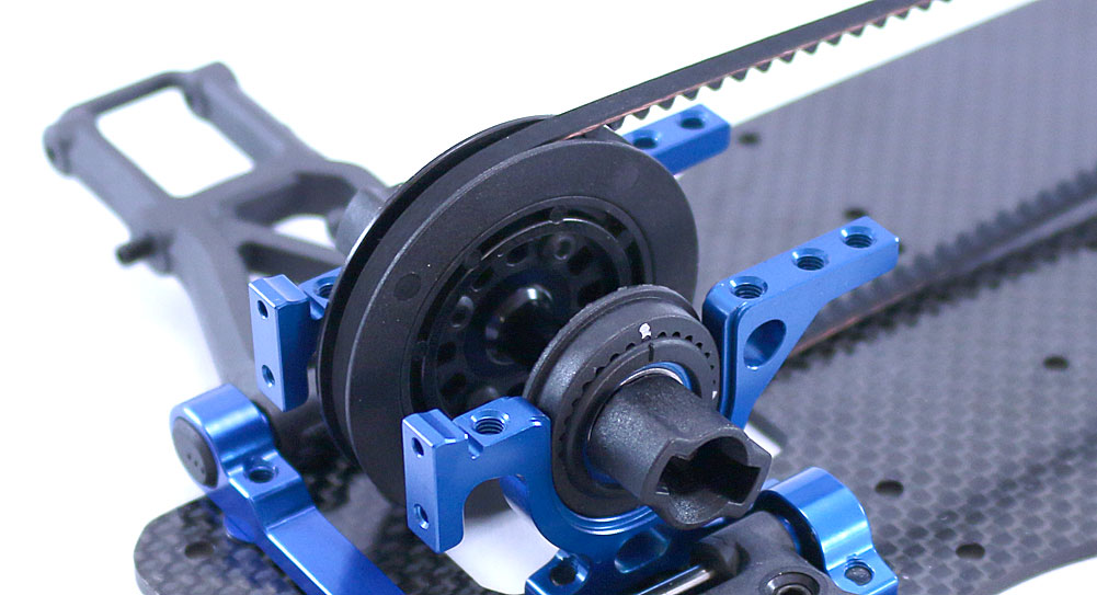
Ring the front drive belt around the spur gear assembly (opposite side of the rear belt pulley) and feed it to the front. Wrap it around front spool and insert the spool into the bulkhead. Make sure the flange on the cam rests inside the groove on the bulkhead. Press firmly into place.
Step 7:
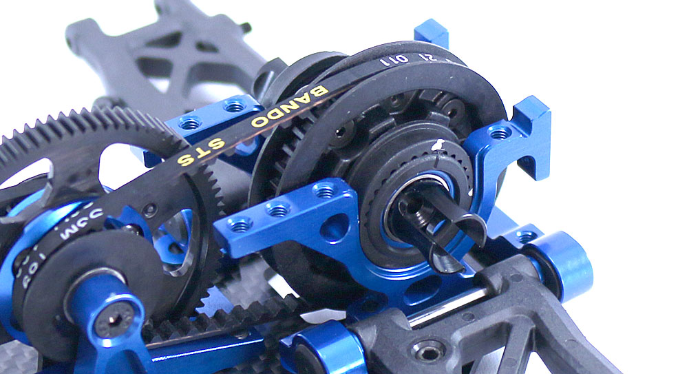
Now wrap the rear belt around the rear diff and insert into the rear bulkhead. Same deal with the cam flange and bulkhead groove applies here. Note the orientation of the cam – Hole #7 towards the back.
Step 8:
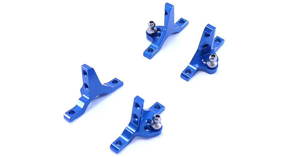
Assemble the four bearing caps as shown, making sure to include the 1mm shim under each ballstud. Note the orientation of the flat spot on the bearing cap; they should be facing foward.
Step 9:
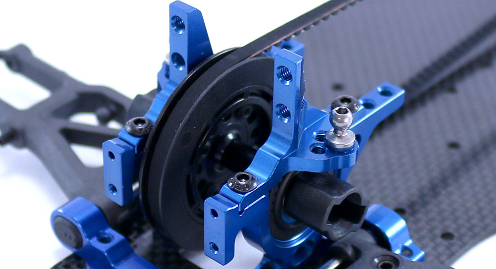
Attach a pair of bearing caps to the front bulkhead. A light dab of blue threadlocker is suggested.
Step 10:
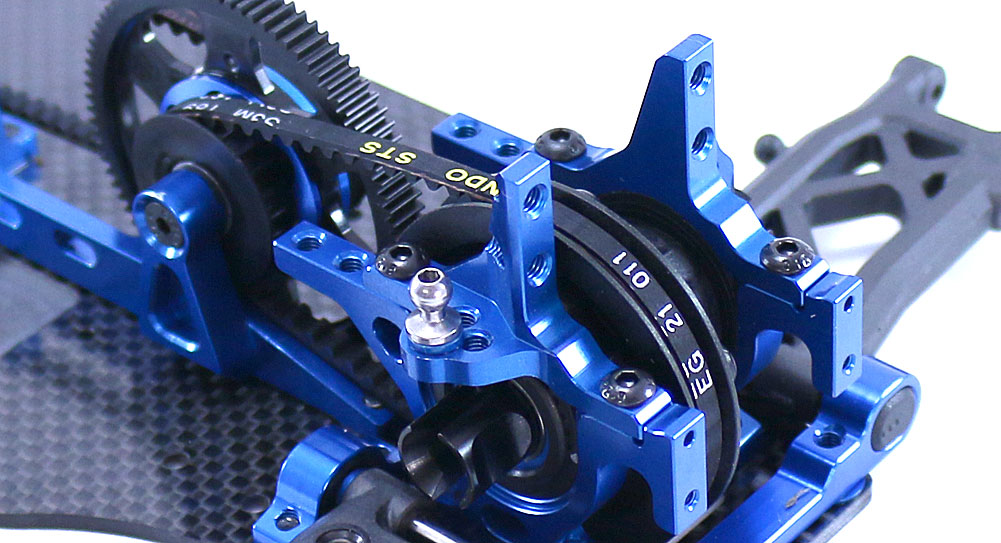
Attach a pair of bearing caps to the rear bulkhead. A light dab of blue threadlocker is suggested here as well.
Step 11:
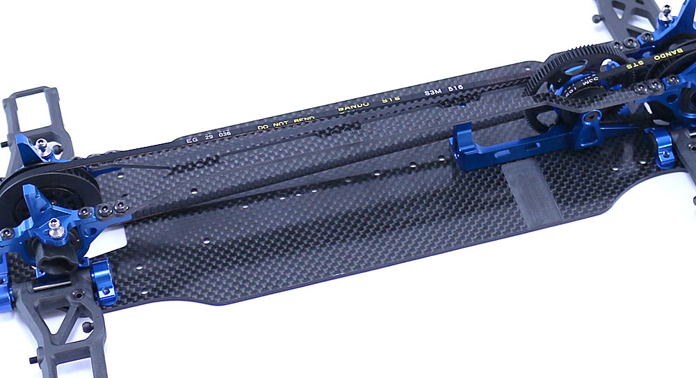
Feed the carbon fiber top deck between the front belt and attach to the front and rear bulkheads. Insert the screws only a little way, then tighten down in a criss-cross pattern. Again, a light dab of blue threadlocker is suggested.
Step 12:
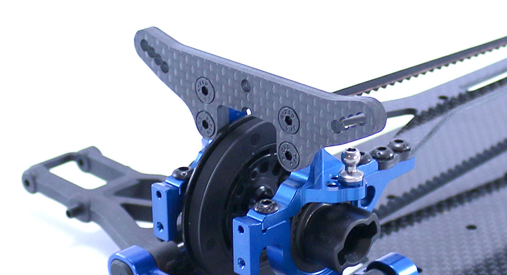
Attach the front shock tower to the front bearing caps.
Step 13:
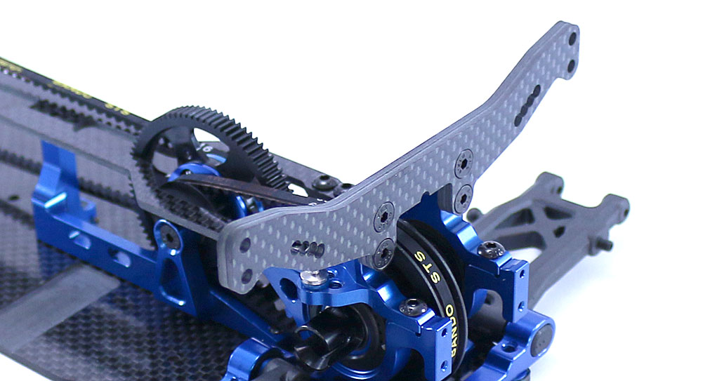
Attach the rear shock tower to the rear bearing caps.
Step 14:
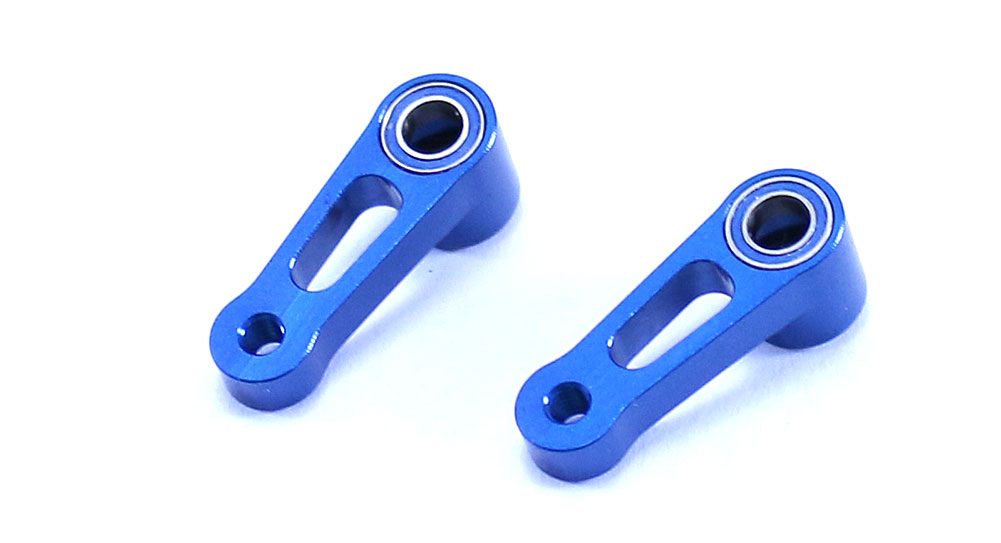
Press the 4x7mm bearings into the aluminum steering bellcranks.
Step 15:
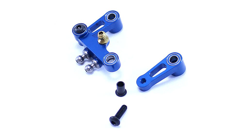
Assemble the steering rack as shown – ballstuds (with 1mm washers), 4x7mm bearings and the TIN 3.25mm ballstud. Slip the steering rack bushings up through the assembled rack and attach the two bellcranks. Blue threadlocker is suggested here.
Step 16:
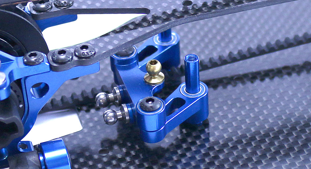
Slide the assembled steering rack over the aluminum steering posts and attach to the chassis with the 3x6mm screws (yes, blue threadlocker here as well). The instructions mention slipping the steering post spacers onto the steering posts at this point, but let’s leave them off for now. Unless you use a screw to keep them in place, they’re going to fall off every time you attach a new piece to the chassis (and that’s alot!). We’ll add them later.
Starting to look like a car now, isn’t it? Next up: the drivetrain!
Team Associated TC7 Online Build – Part 5
Part 5 of the Team Associated TC7 build has us assembling the drivetrain; installation of the steering and rear hubs. We’ll also be using the turnbuckles we built earlier.
Build Notes:
• While not really a build note, I would like to bring attention to the new king pin bushings Team Associated has elected to use. Prior, you were required to feed a bushing into the top and bottom caster block holes from the inside, hold them in place and, using a third hand, carefully slide the assembled steering block into place. That system has been scrapped in place of slightly longer, unflanged bushings that insert from the top. Is it better in the long run, who knows … but it makes me happy now so that’s really what counts.
• When attaching the links (steering and camber), make sure the notches on them are all facing the same way. This will make it easier when it comes to making adjustments on the car.
Step 1:
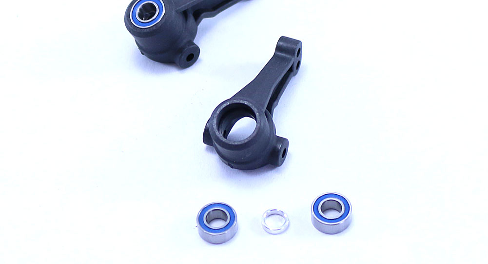
Let’s start by pressing the 5x10mm bearings into the front steering blocks with the chrome crush tube in between them.
Step 2:
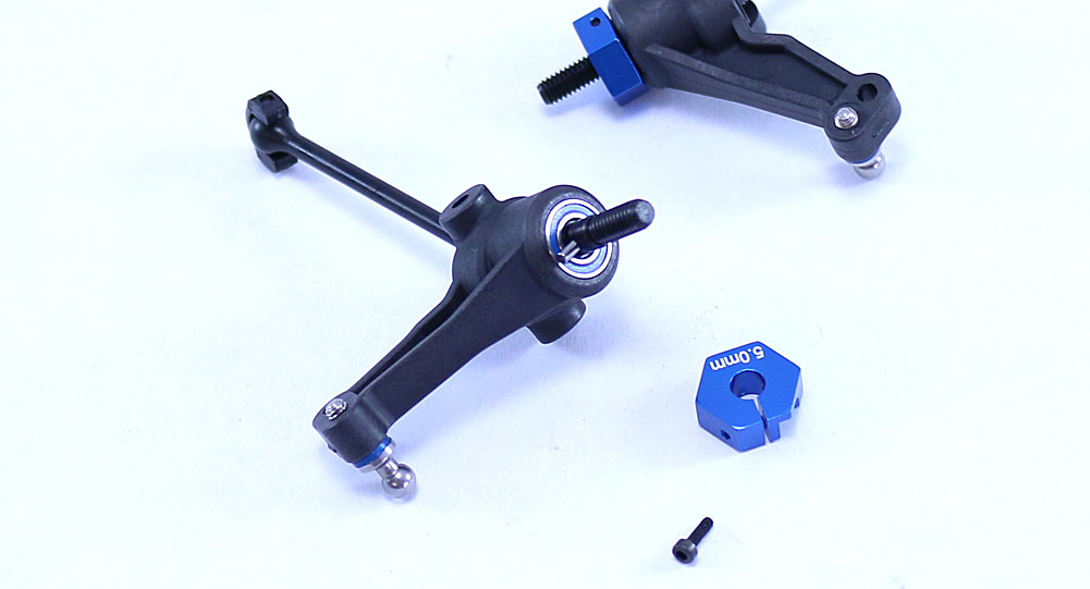
Slip one of the assembled CVA axles through the steering block and insert the 1/16″ pin. Slide the wheel hex onto the axle and key it to the pin, using the 1.6x5mm screw to clamp the hex into place. Attach the 5mm ballstud and 1mm shim to the outside hole (see photo). Build a left and right side version.
Step 3:
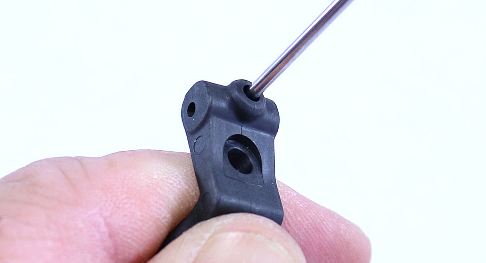
I’ll be attaching the steering blocks to the caster blocks, however before I do I have to poke a hole in the ‘web’ that forms over the set screw hole. A solid push with the tip of your driver will clear the webbing out.
Step 4:
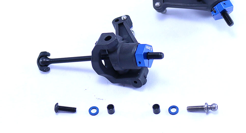
Slide the CVA through the caster block, then line up the upper and lower holes in the caster and steering blocks. Drop one of the new (and WAY easier to use) king pin bushings into the hole and use the 10mm ballstud up top and the 3x10mm BHCS on the bottom to complete the assembly. Don’t forget to include the 1mm shim under both.
Step 5:
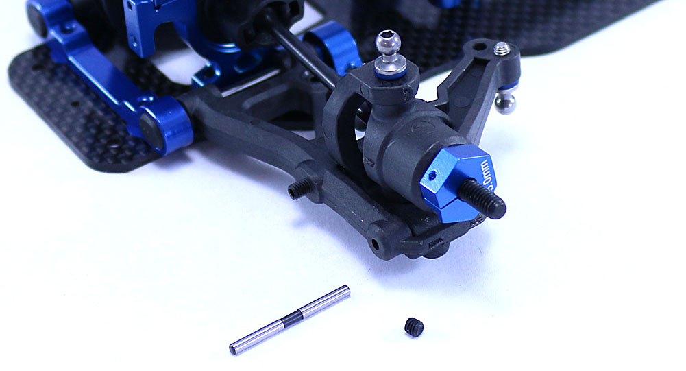
Slip the steering/caster block into the front suspension arm and slide the outer hinge pin through to secure. The 3x3mm set screw is inserted into the bottom of the caster block and holds the hinge pin in place. It should be snug; do not overtighten.
Step 6:
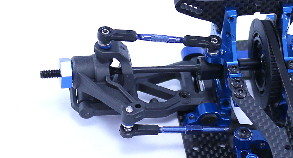
Key the CVA to the spool and snap both the front camber link and steering link into place (on both sides). Note the notches in the turnbuckles are pointed the same directions; make sure they are this way on both the right and left sides.
Step 7:
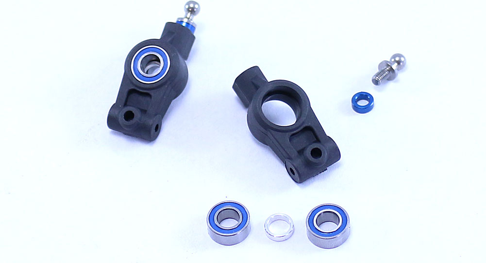
Build the rear hubs – two 5x10mm bearings, crush tubes, 8mm ballstud and 2mm shim. Install in the innermost hole.
Step 8:
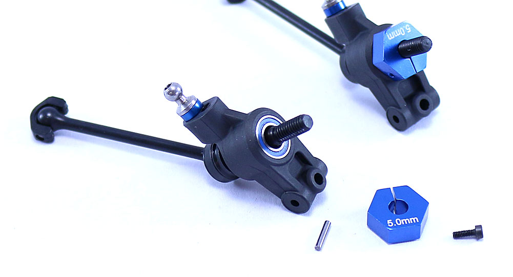
Slide a CVA through the rear hub and insert the 1/16″ pin. Key the wheel hex to the pin and clamp it on.
Step 9:
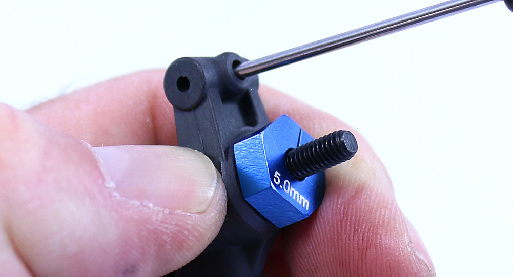
Like we did in Step 3, use the tip of your driver to poke a hole through the webbing in the set screw hole.
Step 10:
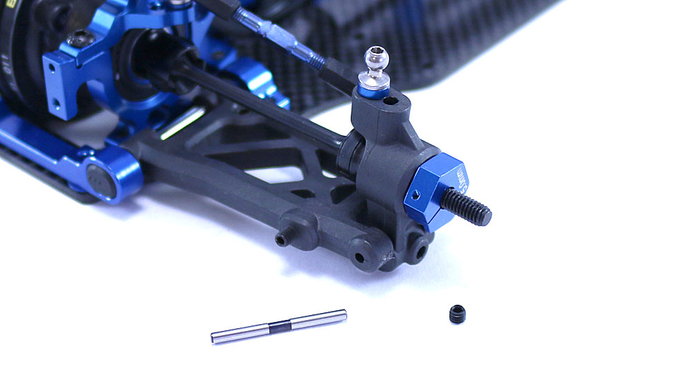
Set the rear hub in place and slide the outer hinge pin through. Use the set screw to secure. Key the CVA to the rear diff and pop the rear camber links on. Make sure the notch in the rear link matches the direction of the notches in the front links.
Look at that … one step closer. On to the installing the shocks, bumper and body mounts!
Team Associated TC7 Online Build – Part 6
In Part 6, I will be attaching the shocks, front bumper and battery mounting parts. Easy peasy.
Build Notes:
• There was a rumor floating around that any body used on the TC6.2 would be a direct fit on the TC7, however Team Associated has updated their body mounts, making them slightly thicker than before. This is great, but when I tried to fit my TC6.2 body on, I had to flex the body to make it fit. If you really want to make your TC6.2 body fit the TC7, the easiest solution is to swap out the body posts. Otherwise you’ll need to hog out the holes in the body. No bueno.
Step 1:
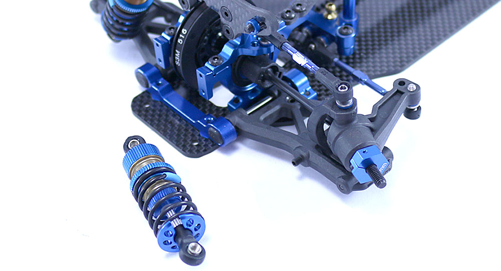
Attaching the front shocks is a pretty simple process; insert the 3x8mm screw into the tower (stock hole is the 3rd hole in), add the 2mm shim and screw into the shock. I suggest using a 3.0mm wrench to ‘hold’ the opposite side of the shock to make sure it’s nice and tight. You’ll need to use that same 3.0mm wrench to attach the lower part of the shock to the suspension arm.
Step 2:
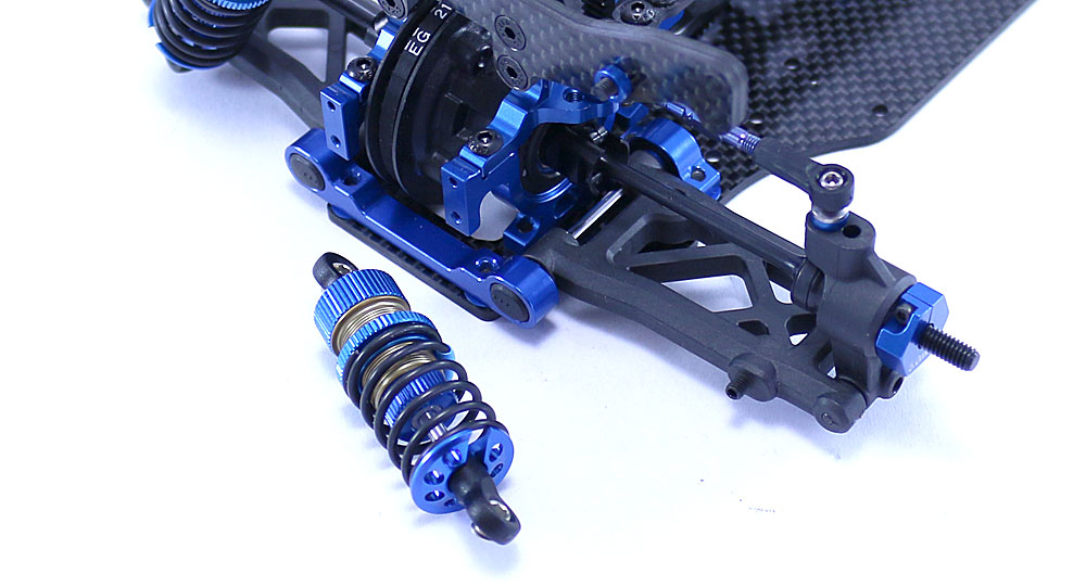
Use the same method to attach the rear shocks, using the 3rd hole in on the tower as well.
Step 3:
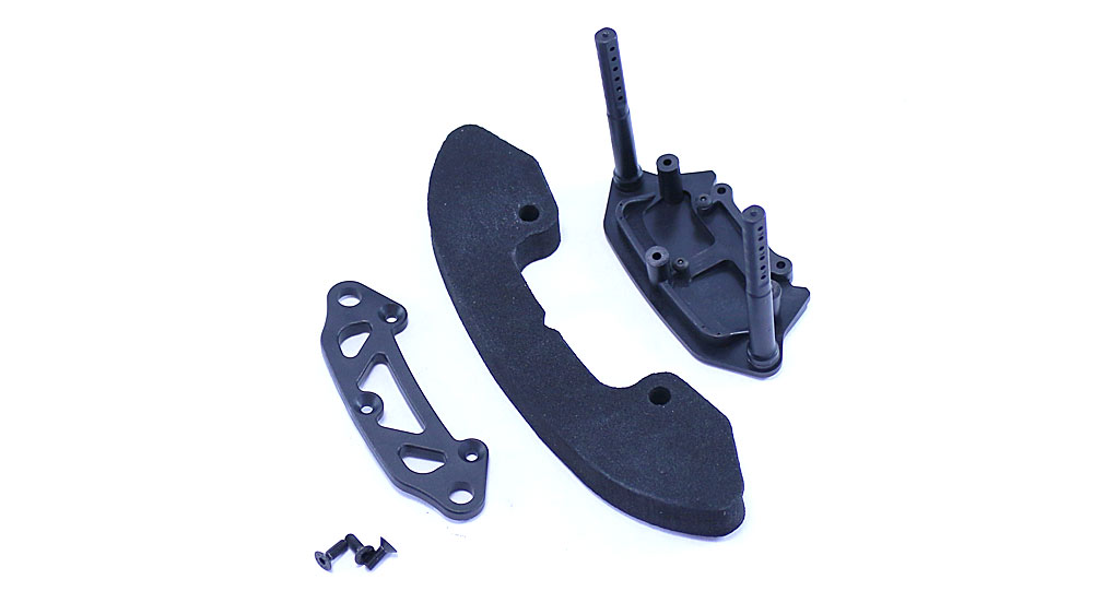
Assemble the front bumper as shown…
Step 4:
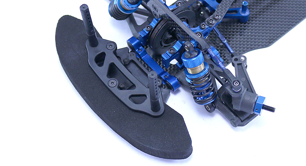
…and attach it to the front of the TC7.
Step 5:
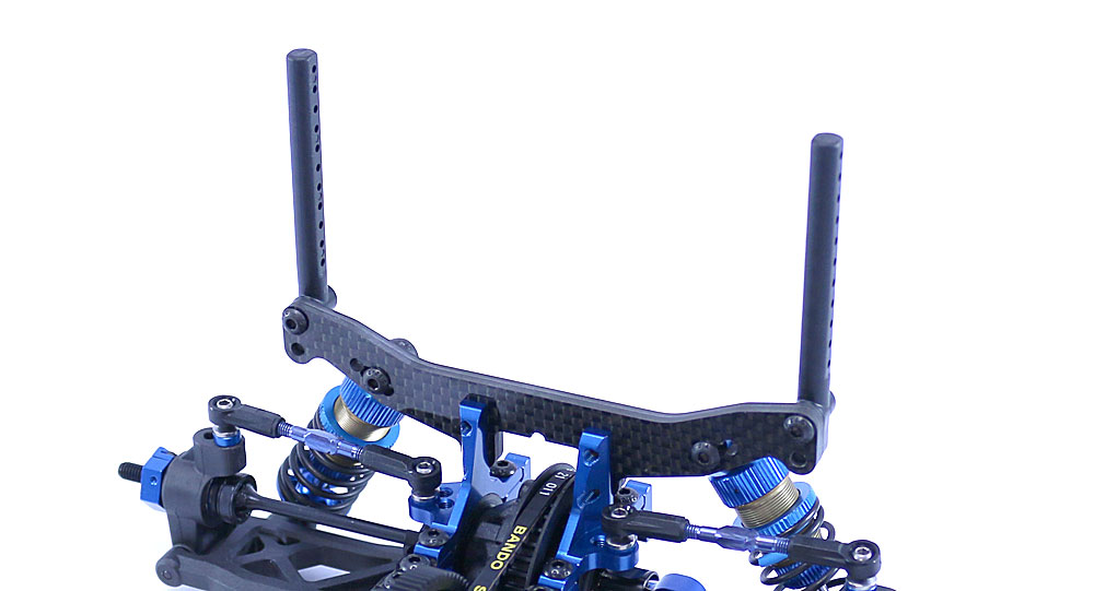
Attach the rear body mounts to the rear shock tower.
Step 6:
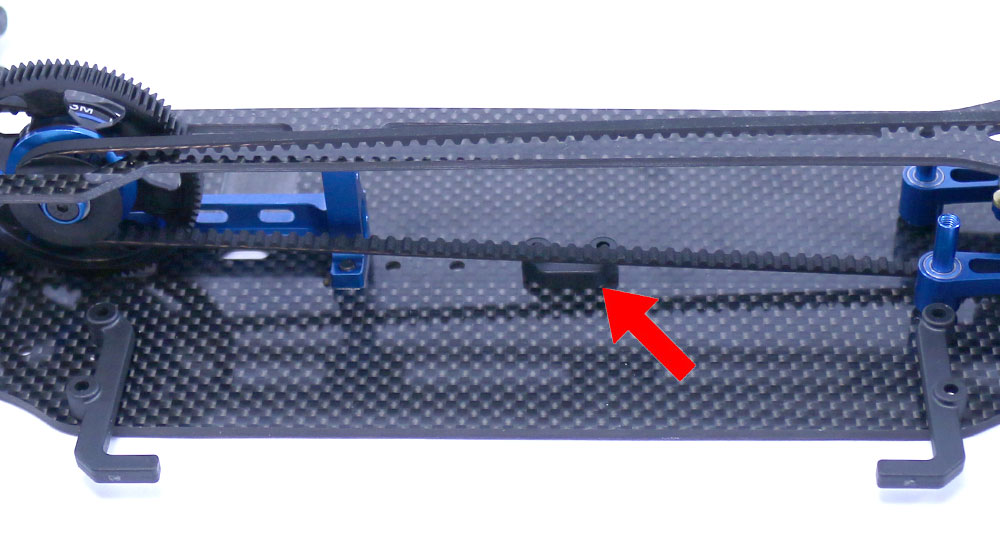
Finally, install the battery tray components. The front and back ‘braces’ are different – the rear one has a slight offset to it for clearance. The red arrow shows the installation of the inner LiPo bumper.
Quick and easy, right? Getting closer – just two more steps to go!
Team Associated TC7 Online Build – Part 7
The Team Associated TC7 comes with front and rear anti-roll bars, both of which are very easy to assemble and install. Follow along.
Build Notes:
• Simple procedure, just make sure you put the 1.4mm bar (blue) on the front and the 1.2mm bar (white) on the rear.
Step 1:
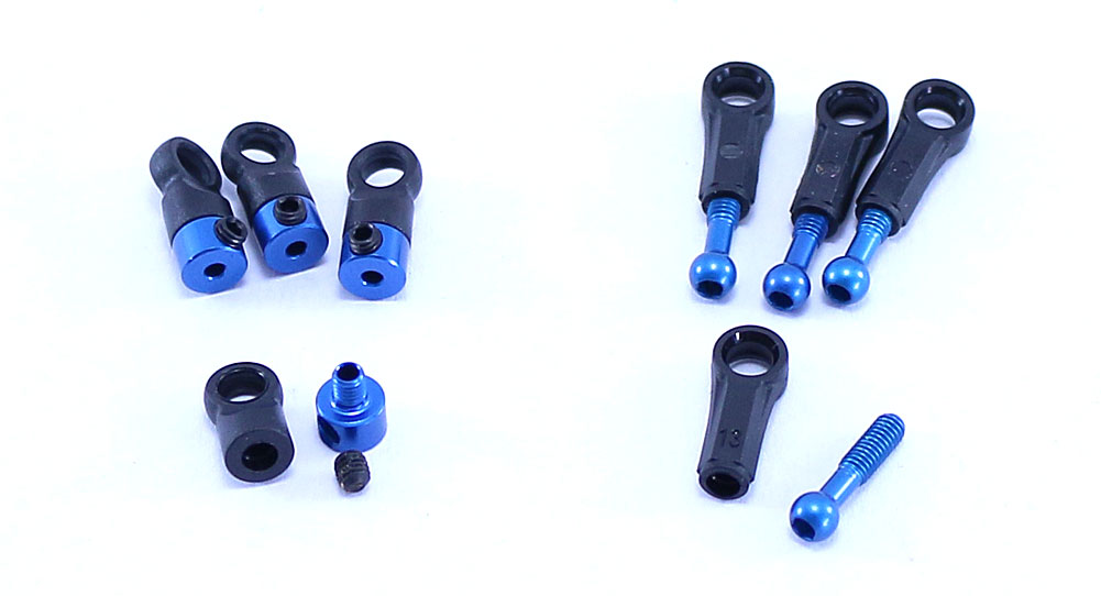
The first thing is to build the anti-roll bar links; screw the couplers and ballstuds into the eyelets. Partially insert the set screws into the couplers; I’ll tighten them in a bit.
Step 2:
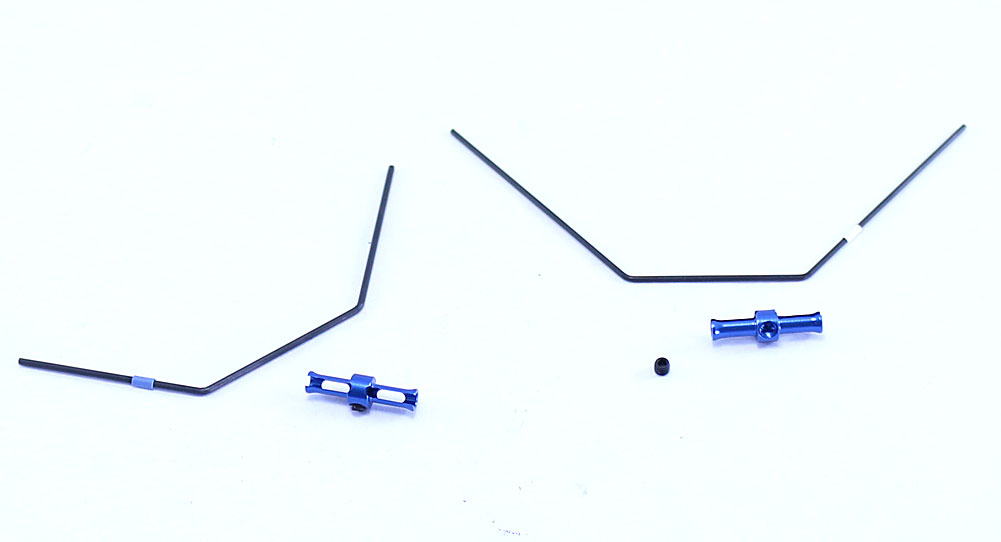
Shinking the colored wrap to the bars is optional, but I like to have it to help identify what bars I’m using. Once you’ve decided how to handle that major delimma, slip the bar through the retainer, center it and insert the set screw.
Step 3:
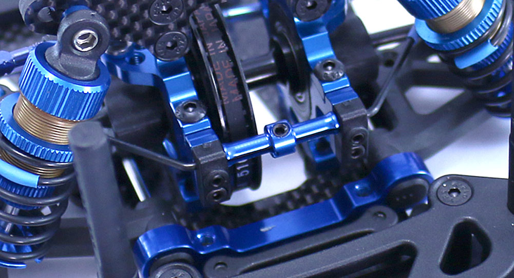
Set the anti-roll bar in place and secure with the pair of plastic mounts. Screw the 3x3mm set screws into the mounts until they JUST comes in contact with the bar. The bar should move freely; if it doesn’t, back the set screws off slightly.
Step 4:
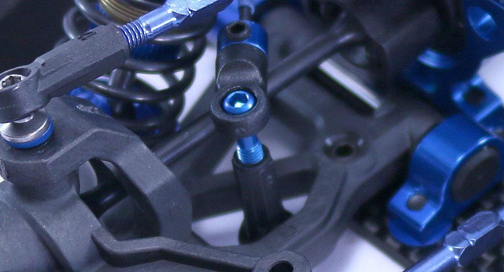
Pop the anti-roll bar mounts onto the balls on the suspension arms, then slide the end of the anti-roll bar into the coupler. Tighten the ‘partially inserted’ set screw to lock the anti-roll bar in place.
Step 5:
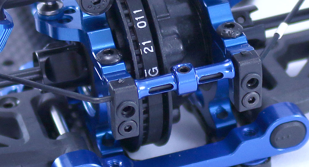
Follow the same procedure to attach the rear anti-roll bar.
Step 6:
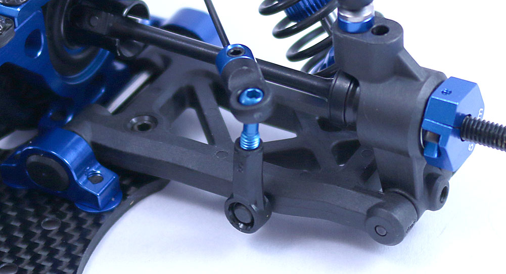
Team Associated TC7 Build – Anti-Roll Bar – Step 6[/caption]
While the mounting point is slightly different, use the same method as we did in Step 4 to attach the links.
Roll controlled. One more step – the electronics. See ya there!
Team Associated TC7 Online Build – Part 8
I am lucky enough to not only get one of Team Associated’s TC7s, I’m also able to load it up with a full set of Reedy electronics! In addition, I’ll be installing an XP servo and Futaba radio system. Oh so good…
Build Notes:
• You might notice that my build started off with 48P gears but towards the end swapped over to 64P. I did this for the simple reason that, with a 13.5T motor, trying to get to the ‘suggested’ 4.1-4.5 gear ratio was becoming quite the chore. I have WAY more 64P gears than I do 48P, so I figured I’d switch to make life easier.
Step 1:
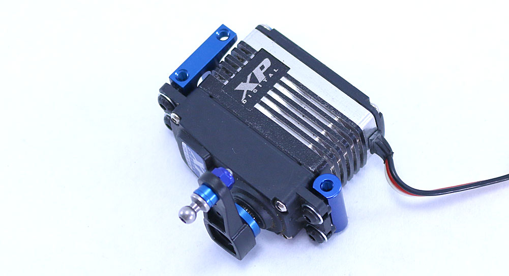
The first order on the bench is to get the XP DS1313 servo connected and installed. Assemble and attach the servo horn as well as the pair of servo mounts. Leave the screws slightly loose on the mounts for now, and leave off the antenna mount for the time being.
Step 2:
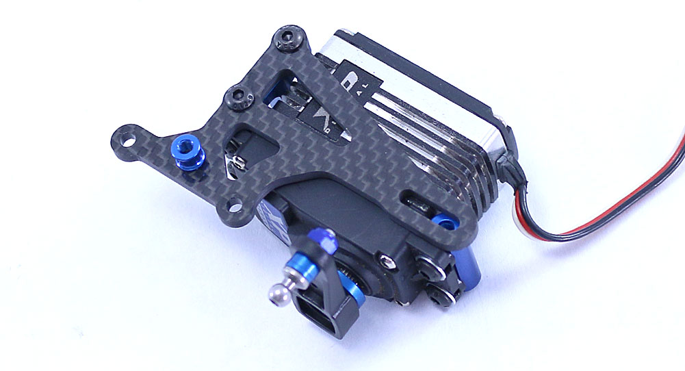
The manual shows the carbon fiber floating servo mount going on later, but that poses a problem unless you want to remove the top deck. I didn’t, so I assembled and installed it now. Once the mount is attached, you can tighten up the servo mount screws from the last step.
Step 3:
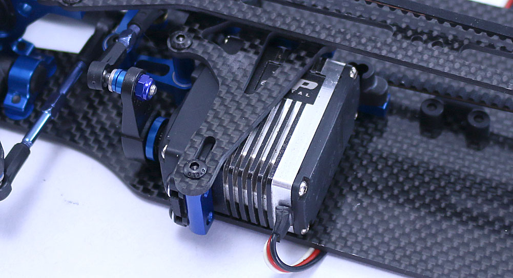
Before sliding the servo onto the chassis, install the aluminum servo spacers over the servo posts now. Slide the servo assembly into place and attach to the chassis. Two screws are used to attach the floating servo mount to the servo posts, capturing the spacers. Don’t forget the screw that attaches this assembly to the top deck. It’s also time to attach the antenna mount. Note that the opening for the antenna is extremely close to the servo, so you might want to leave this screw loose until you’ve fed the antenna through the opening.
Step 4:
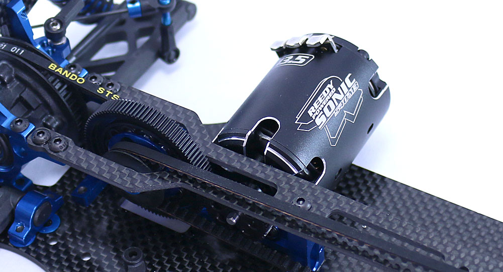
Attach the motor. You might also notice the 64P gears instead of the kit supplied 48P. Read the above notes for more info on that.
Step 5:
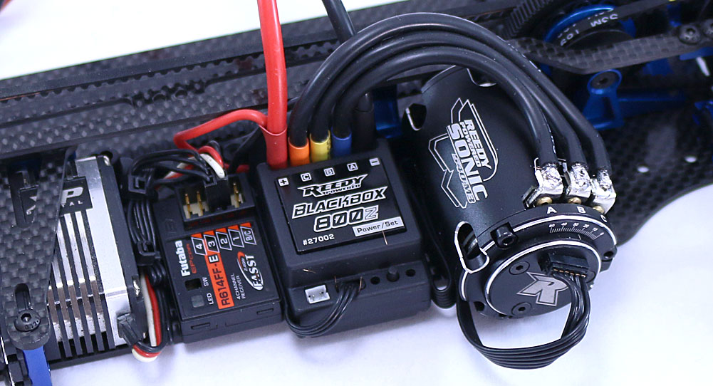
Install the receiver and ESC and wire everything up. It’s a bit compact on the chassis but as you can see there’s room for a clean install.
Step 6:
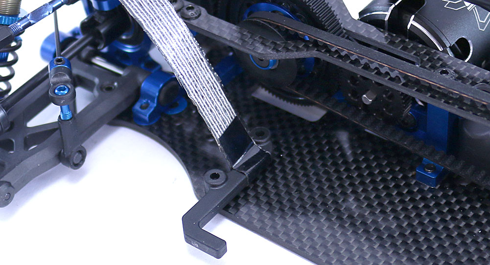
The TC7 requires tape to hold the battery in place. To use, simply form a hoop around the mount and attach the tape to itself. I use MuchMore’s reinforced tape to keep my battery firmly planted.
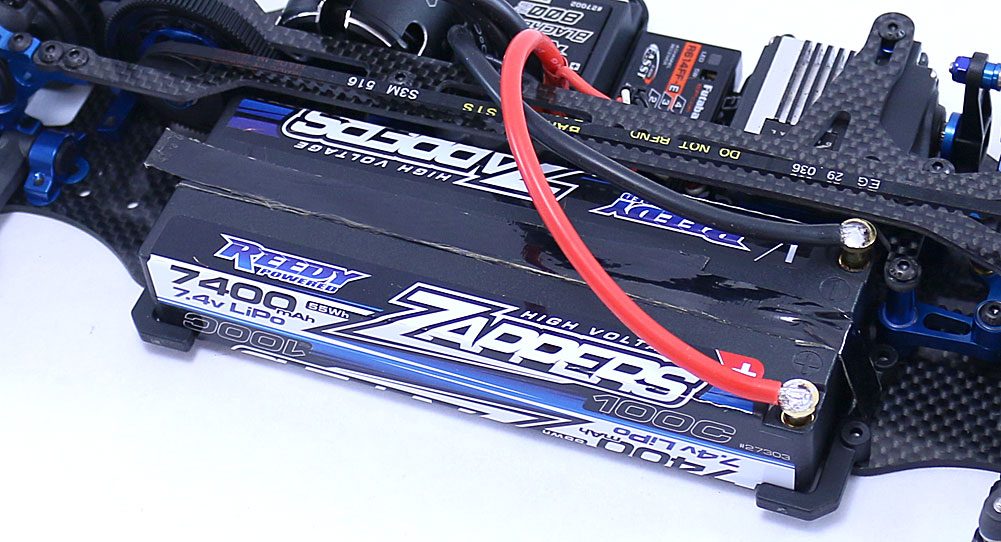
Step 7:
Drop your battery in, wire up the power plugs and boom … you’re ready to rock!
Congratulations! You’ve wrapped up your brand new Team Associated TC7!
Now, if you’re like me, you can’t wait to get this baby out on the track. I would install some tires and do a bench test to make sure everything is working and there are no problems prior to putting it out on the track!

