
Axial Yeti XL Online Build
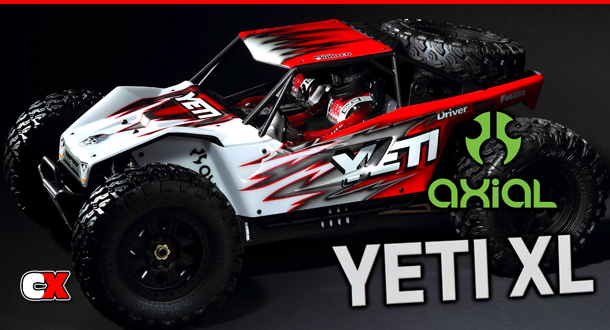
Axial has done a great job at focusing their efforts towards scale releases. Their line of scale trail trucks has been hugely popular, so it was a nice change to see them venture off and build a rock racer like the Yeti.
However, Axial’s forward thinking not only gave us a 1/10 scale Yeti, the also bumped that business up and surprised everyone with the 1/8 Yeti XL! This is a beast of a vehicle and thankfully we got a chance to build the kit version you see here. It’s a pretty big box with a lot of parts, so let’s get right down to it.
Axial Yeti XL Online Build – Part 1
The first thing Axial has you doing is building the front differential. It’s like any standard fluid-filled diff, however it’s massively over-built to withstand the monster power you can run through this truck.
Build Notes:
• This part of the build requires us to use diff fluid. It’s a good idea to have a clean working surface that is covered with a towel (or something similar) and some clean-up rags.
Step 1:
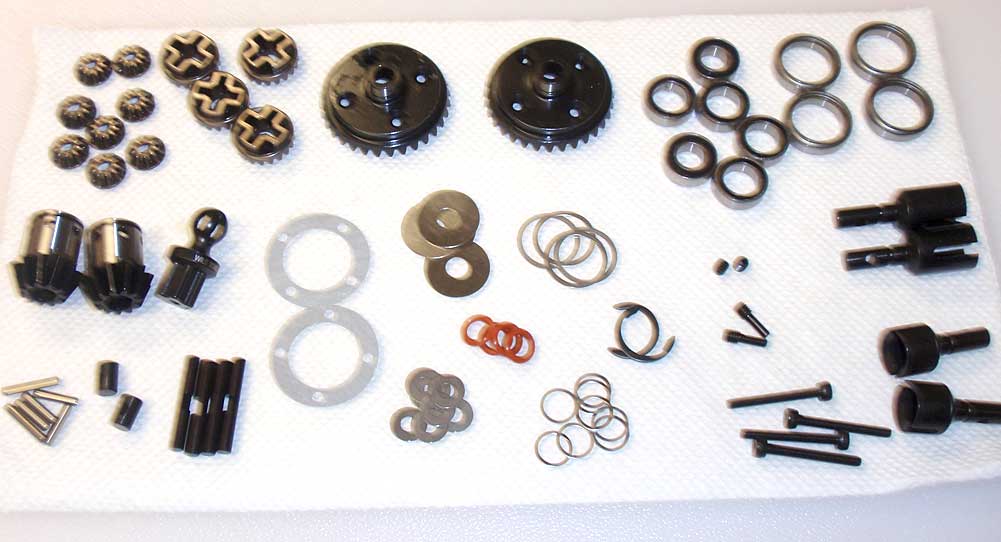
Since both the front and rear diffs are essentially the same (other than the drive cups), I started this part of the build by separating all of the parts to make it easier to recognize what I needed. Sorry for the blurry picture; not sure what happened there.
Step 2:
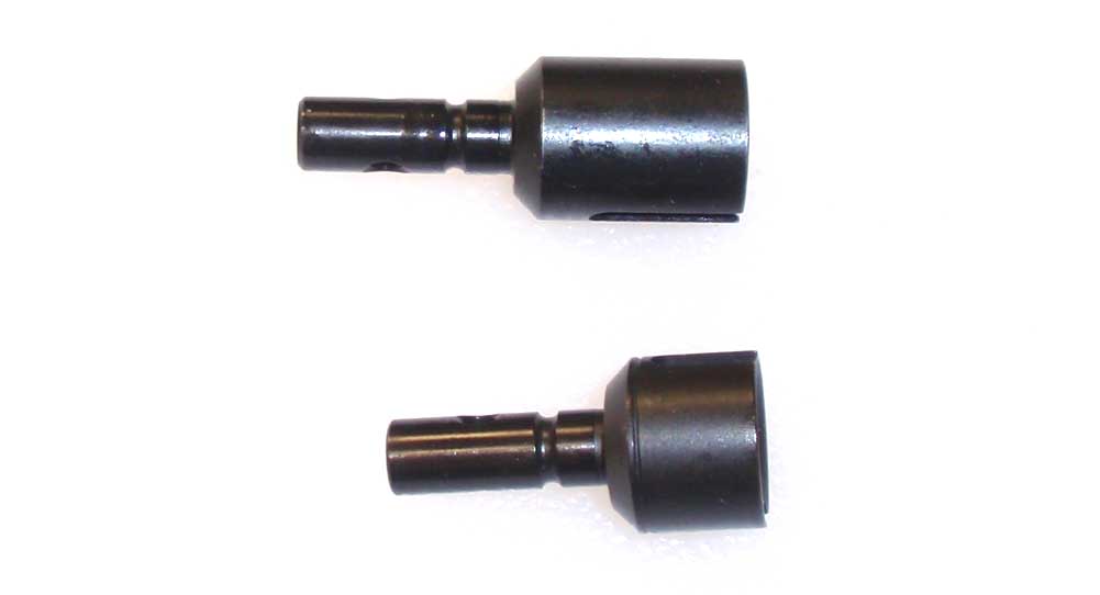
Speaking of the drive cups, I’ve shown both here for reference. The top one is for the front (this build step), the lower one is for the rear.
Step 3:
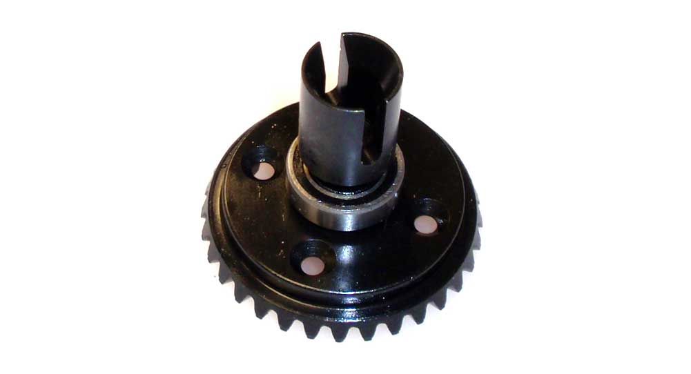
Slip one of the 8×16 bearings over the diff gear and slide the front drive cup through.
Step 4:
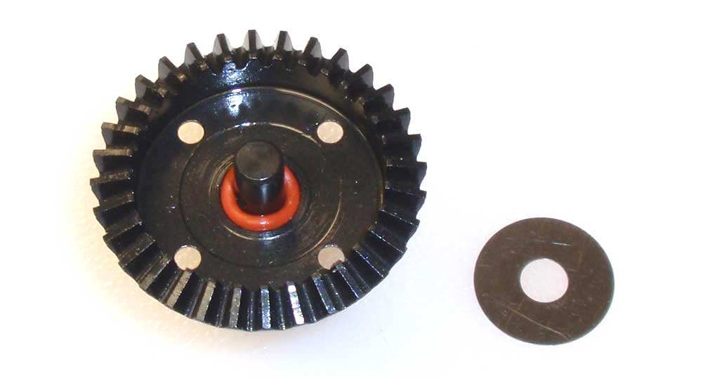
Flip the assembly over and slide a red o-ring over the drive cup shaft followed by a 6×19 shim. Press the shim down firmly to seat the o-ring.
Step 5:
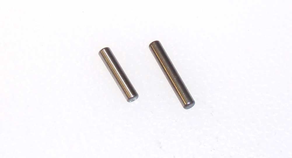
There are two lengths of drive pins as well. The short ones will be used during the diff build; the longer ones for the CVD build.
Step 6:
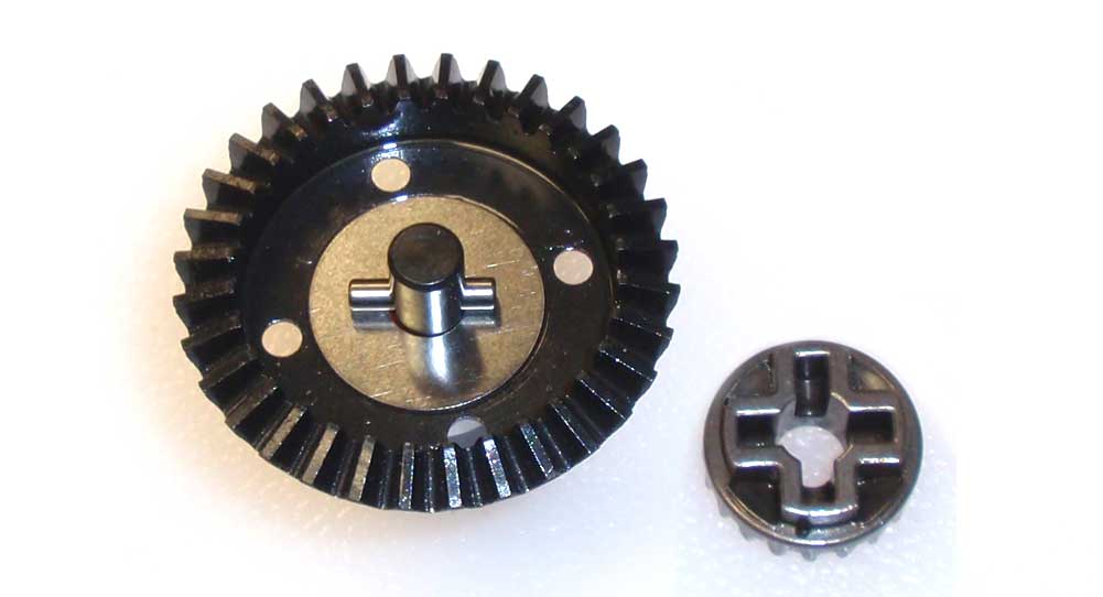
Slide one of the shorter pins through the drive cup shaft as shown. Take one of the metal sun gears, slide it onto the shaft and key it to the pin. Set this assembly aside.
Step 7:
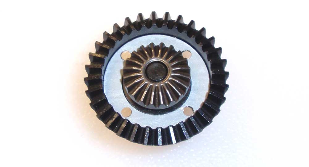
Carefully set the diff gasket into place, lining the holes up with the holes in the gear.
Step 8:
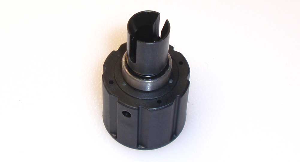
Slide one of the 8×16 bearings onto the diff housing as shown. Take the other front drive cup and slide it into place.
Step 9:
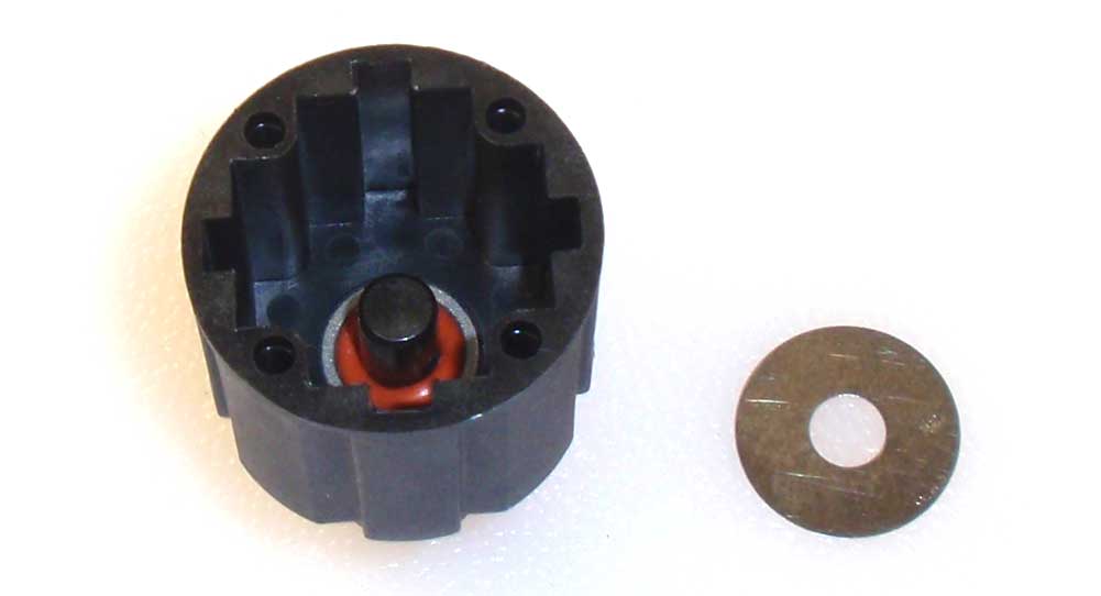
Flip the assembly over and slide a red o-ring over the drive cup shaft followed by a 6×19 shim. Press the shim down firmly to seat the o-ring.
Step 10:
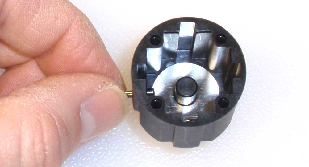
Line up the hole in the outer housing with the hole in the drive cup shaft. Slide one of the shorter pins through the housing and into the drive cup shaft.
Step 11:
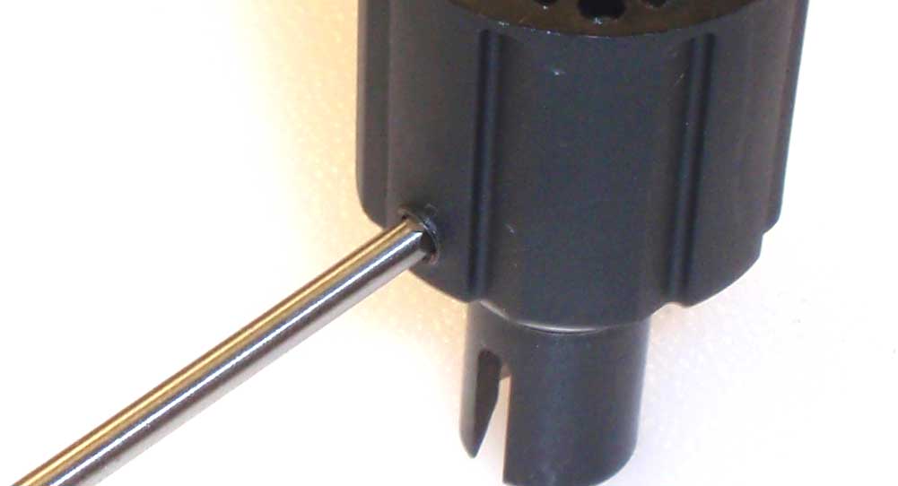
Once the pin is installed, screw a M4 setscrew into the hole and make it flush with the outside of the diff housing. This will seal the diff and keep any fluid from leaking out.
Step 12:
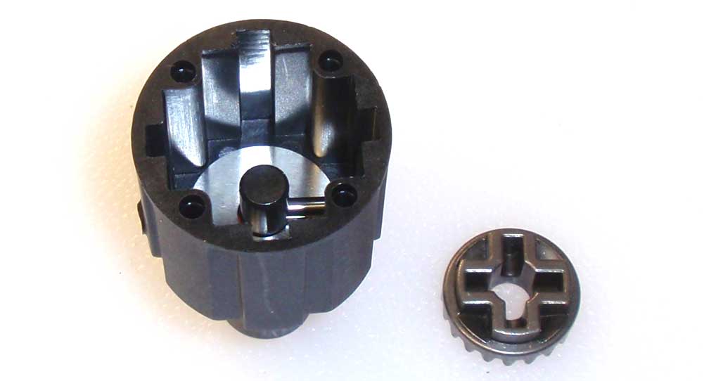
Flip the diff housing over and slide the sun gear over the drive cup shaft, keying it to the pin.
Step 13:
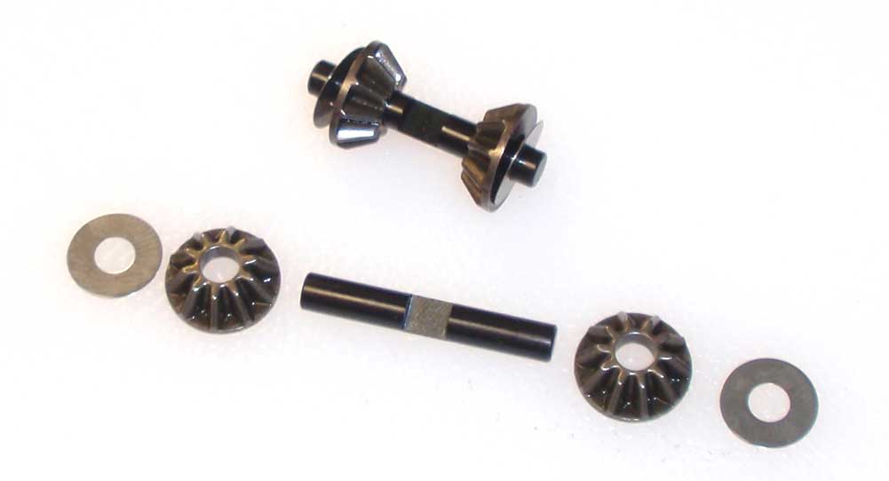
Build two sun gear assemblies.
Step 14:
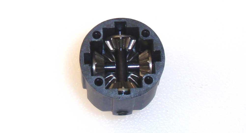
Lining the sun gear assembly shaft up with the notches in the housing, place one assembly into the diff, making sure the flat spot on the shaft is facing up. Place the second sun gear assembly into the diff, making sure the flat spot on the shaft is facing down. They two flat spots should key together. While holding the assemblies in place, slowly turn the drive cup to make sure both sun gear assemblies are completely seated.
Step 15:
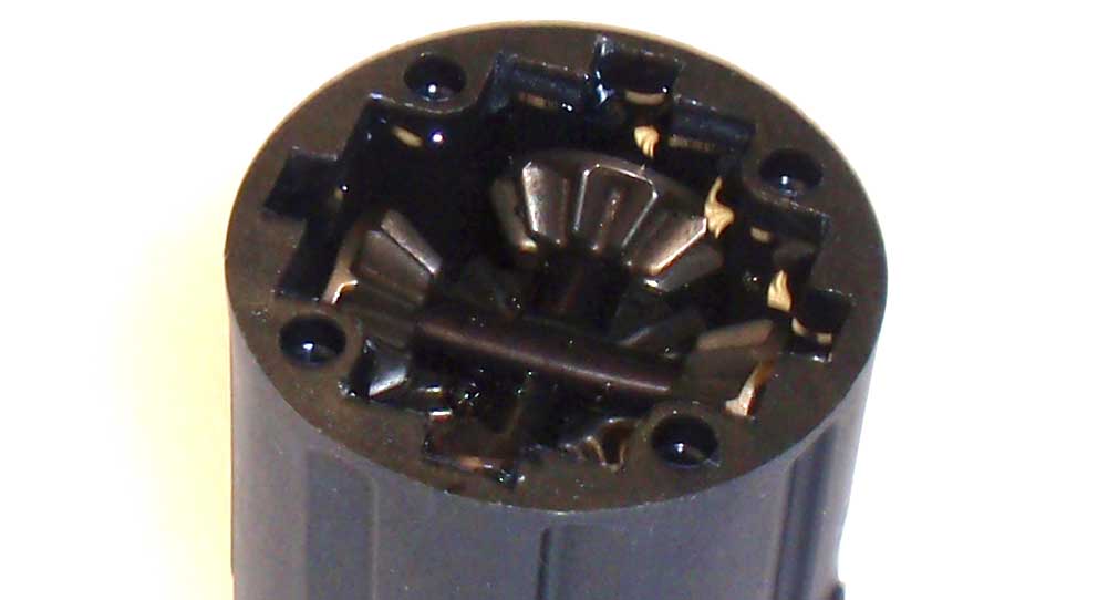
Fill the diff housing up with the included 20000CST fluid. Put just enough that it covers the top of the gears.
Step 16:
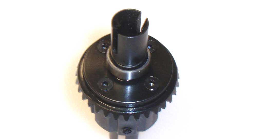
Take your gear-side assembly and flip it over onto the housing side, making sure you line up the holes in the gear to the holes in the housing. Screw together slowly, rotating the drive cups once or twice to make sure they are meshing correctly.
Step 17:
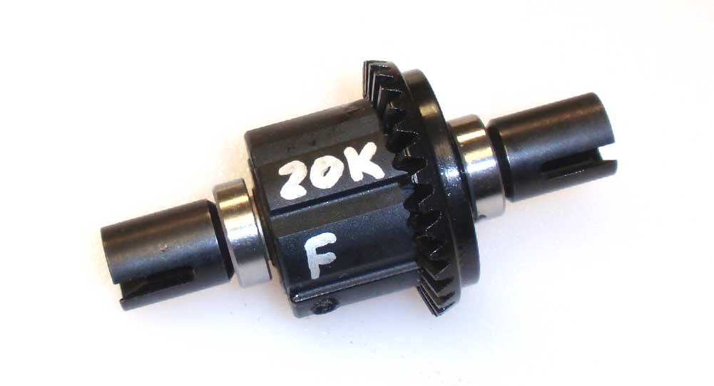
I like to write on the diff what fluid is in it as well as which end of the car it goes. Of course this is completely optional, but it is a good idea to help you keep track.
Front differential done!
Axial Yeti XL Online Build – Part 2
The second part of the Axial Yeti XL build has us installing the front differential into the front gearbox.
Build Notes:
• Check and double check to make sure that you install the front diff in the right direction.
• Be VERY careful when you’re using the M2.6 screws to capture the axle assembly into the gearbox. You need to seat the assembly completely before screwing them in. They’re not very long so if you try to use them to seat the axle you could strip out the plastic.
Step 1:
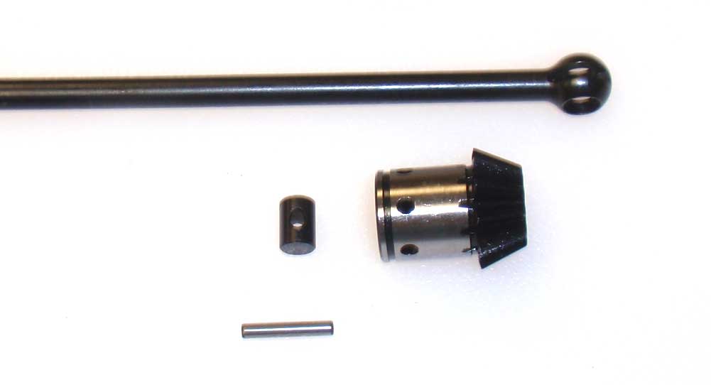
We start off the front gearbox build by assembling the front drive axle. Slide the barrel into the axle ball, then insert that into the 11T diff gear. Insert the pin through the assembly, making sure to line up the holes. Use a little bit of black grease on the ball to lube everything up.
Step 2:
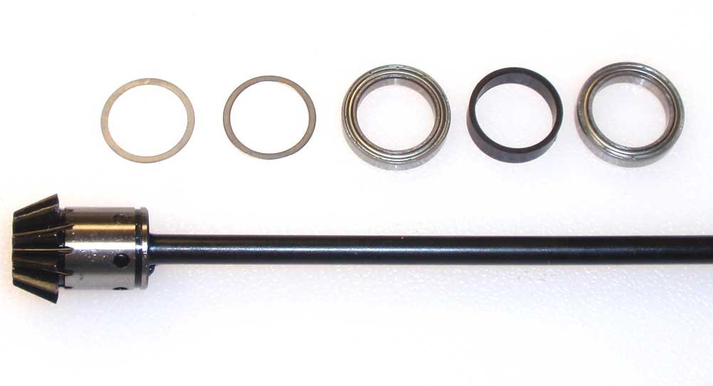
This drive axle doesn’t use a set screw to capture the pin. Instead, we’ll be using a pair of bearings and a spacer to capture it. Start by sliding a pair of 15×18 washers onto the assembly followed by a 15×21 bearing, the plastic spacer and then another 15×21 bearing.
Step 3:
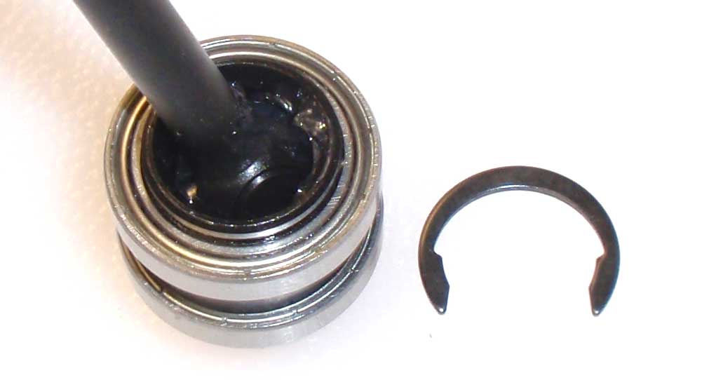
This next part is a little tricky; we’ll be installing the C-clip. The easiest way I found was to stand the axle assembly up, press the bearings/spacer/shims firmly down onto the gear and then insert the C-clip. There is a notch on the gear that the C-clip has to snap into, so make sure you get it in there. Now, with a pair of pliers, carefully snap the clip into the groove.
Step 4:
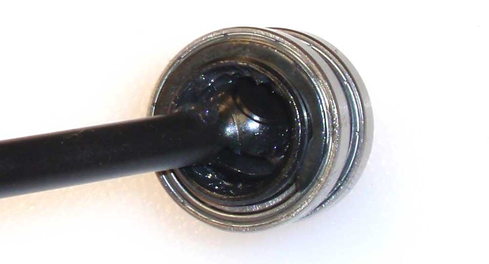
Here’s what the clip should look like.
Step 5:
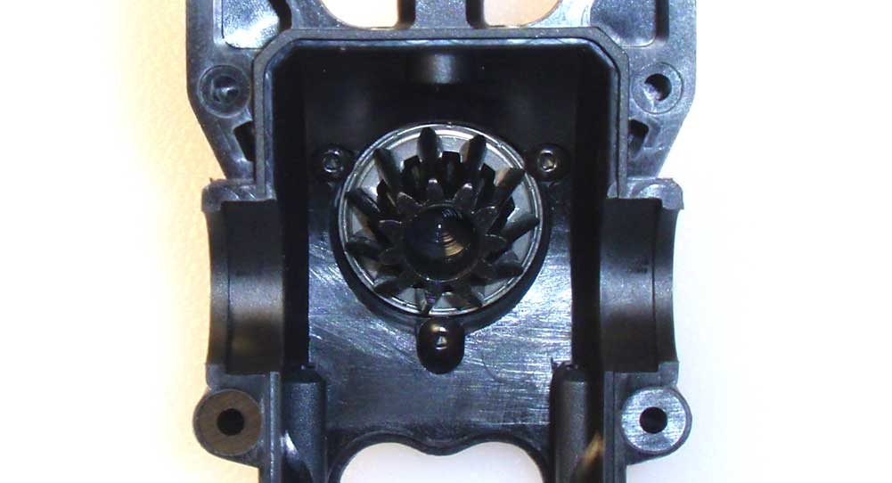
Slide the axle assembly into the rear half of the gearbox. Press the bearings into recess; press them firmly into place. Once fully seated, secure it into place with the 3 M2.6 screws. DO NOT use the screws to fully seat the axle assembly. You could strip out the plastic. This is a pretty crucial assembly step.
Step 6:
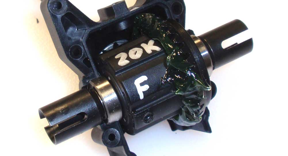
Apply a pretty liberal amount of the supplied grease to the front differential and slide it into place. More is better here.
Step 7:
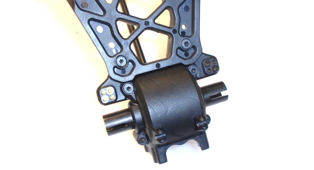
Mate the front half of the gear case to the assembly. Before pressing together, slide the front shock tower between the two halves and screw together. Do not overtighten; snug is good enough.
Step 8:
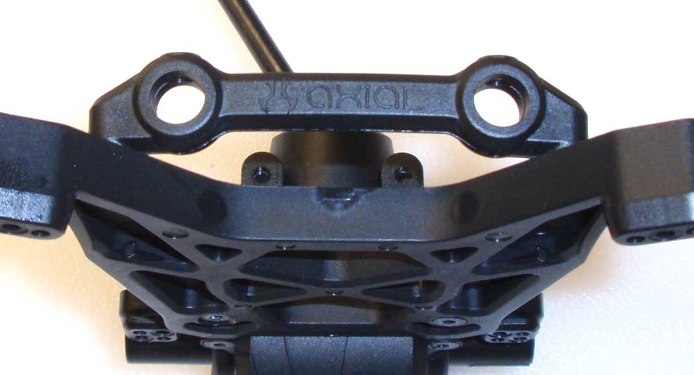
Attach the body mount brace to the backside of the shock tower.
Step 9:
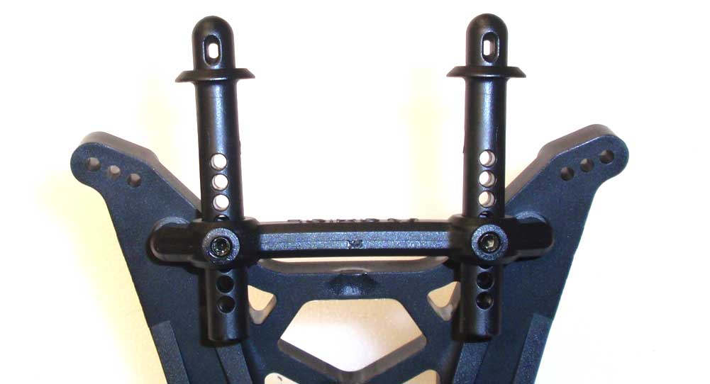
Slide the two body mounts into place and secure with the M4 shouldered setscrews. I used the kit settings for the height adjustments.
Great job. Set the front gearbox assembly off to the side and let’s get crackin’ on the rear.
Axial Yeti XL Online Build – Part 3
Time to build the rear differential. Other than the outdrives, the rear diff build is exactly like the front. You should breeze through this step.
Build Notes:
• We’ll be filling the rear diff with fluid. It’s a good idea to have a clean working surface that is covered with a towel (or something similar) and some clean-up rags.
Step 1:
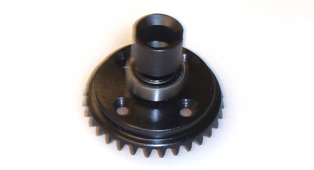
Press one of the 8×16 bearings onto the diff gear. Slide the drive cup into place as shown. Hopefully you’re seeing the short cups like the ones in the picture.
Step 2:
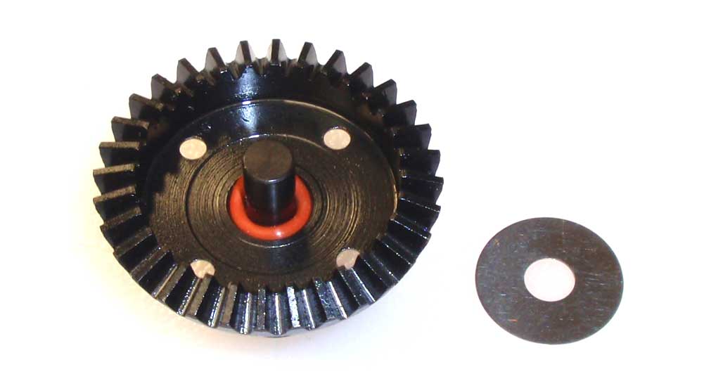
Flip the assembly over and slide the red o-ring onto the outdrive. Place the 6×19 shim into place and press down to seat the o-ring.
Step 3:
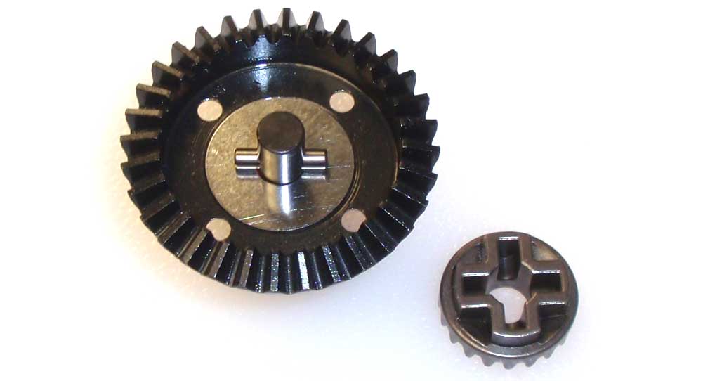
Slide the short pin through the hole in the outdrive. Flip the sun gear over and press it into place, keying it to the pin.
Step 4:
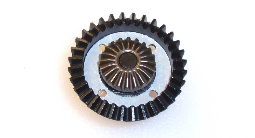
Set the diff gasket onto the gear as shown. Make sure you line up the holes.
Step 5:
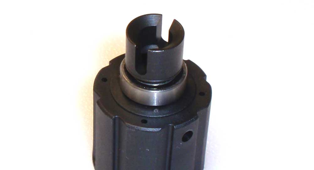
Press the other 8×16 bearing onto the diff housing followed by the short drive cup.
Step 6:
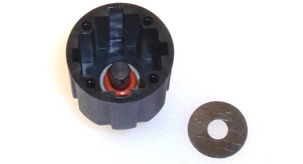
Flip the assembly over and slide another red o-ring onto the shaft. Slip the 6×19 shim onto the shaft and press it down to seat the o-ring.
Step 7:
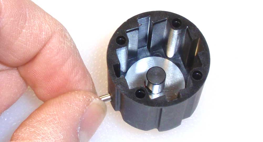
Like the front, you’ll want to rotate the housing to line the holes up. Slide the pin through the housing and into the drive cup.
Step 8:
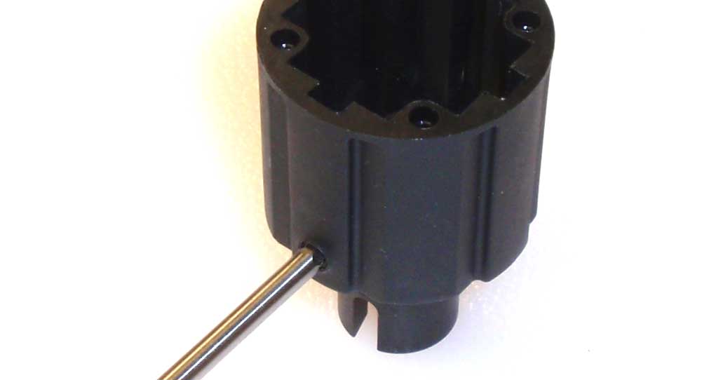
Once installed, seal up the hole with the M4 set screw. Screw it in until it’s flush with the outside of the housing.
Step 9:
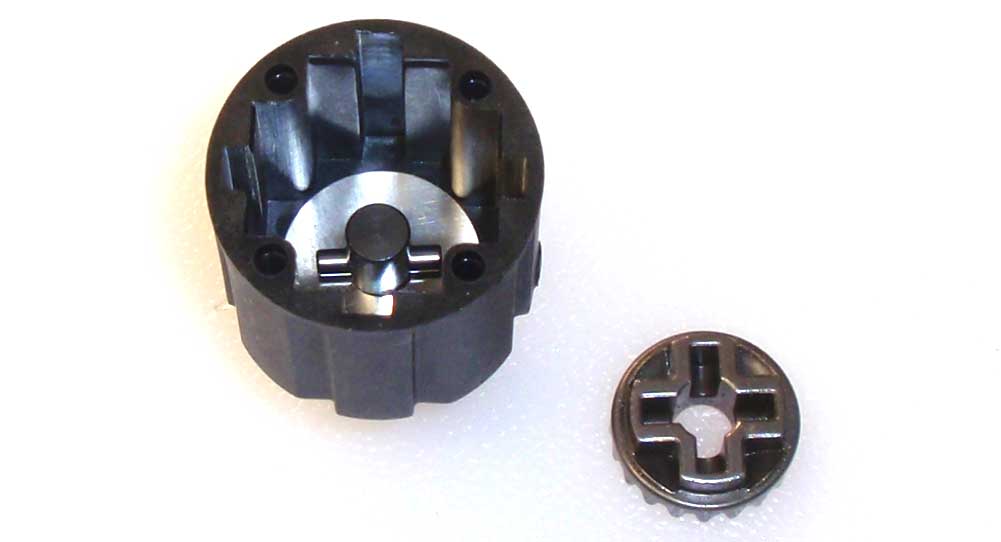
Center the pin and drop the sun gear into place.
Step 10:
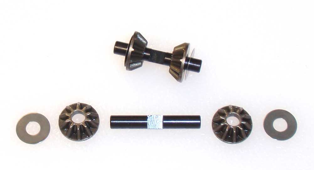
Make two sun gear assemblies.
Step 11:
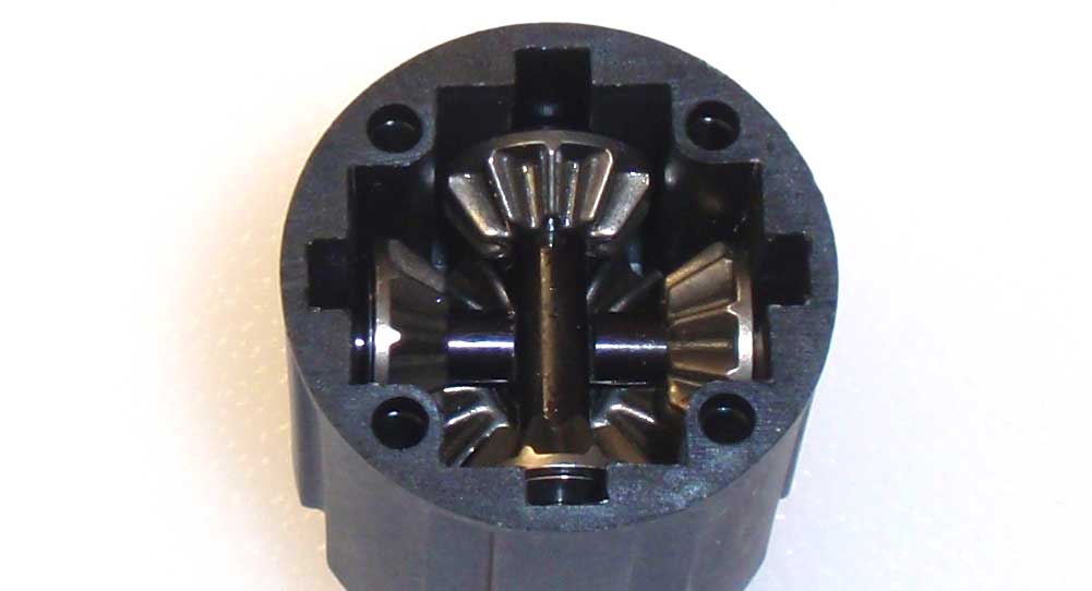
Key one sun gear assembly to the notches in the housing and drop into place. Key the other and drop it into place. Like the front, you’ll want to make sure the flat spots mate when the sun gear assemblies are installed. Rotate the drive cup to make sure all the gears have seated correctly.
Step 12:
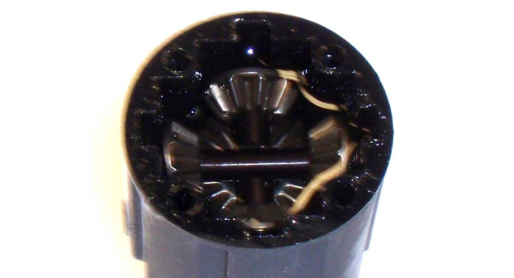
Fill the housing up with the 20000CST fluid up just past the top of the gears. Let it set for a few seconds to make sure the fluid has seeped into all the nooks and crannies. Refill if necessary.
Step 13:
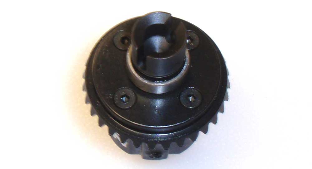
While lining up the holes, set the gear-side assembly on top of the housing side and screw together. Rotate the drive cup a few times during assembly to make sure the gears are meshing correctly.
Step 14:
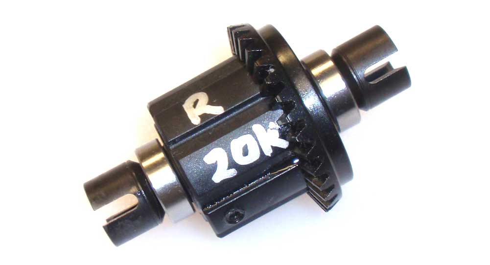
Like the front, I used a silver Sharpie to write the weight and which end of the car the diff goes.
Simple, right? Clean up your area, if needed, and we’ll get the diff installed in the rear axle.
Axial Yeti XL Online Build – Part 4
The Axial Yeti XL uses a little different rear axle than most vehicles. We’ll be building a solid rear axle that includes the diff from our previous step.
Build Notes:
• Pay close attention to the installation of the outer carrier. These are directional and do need to be installed a certain way.
Step 1:
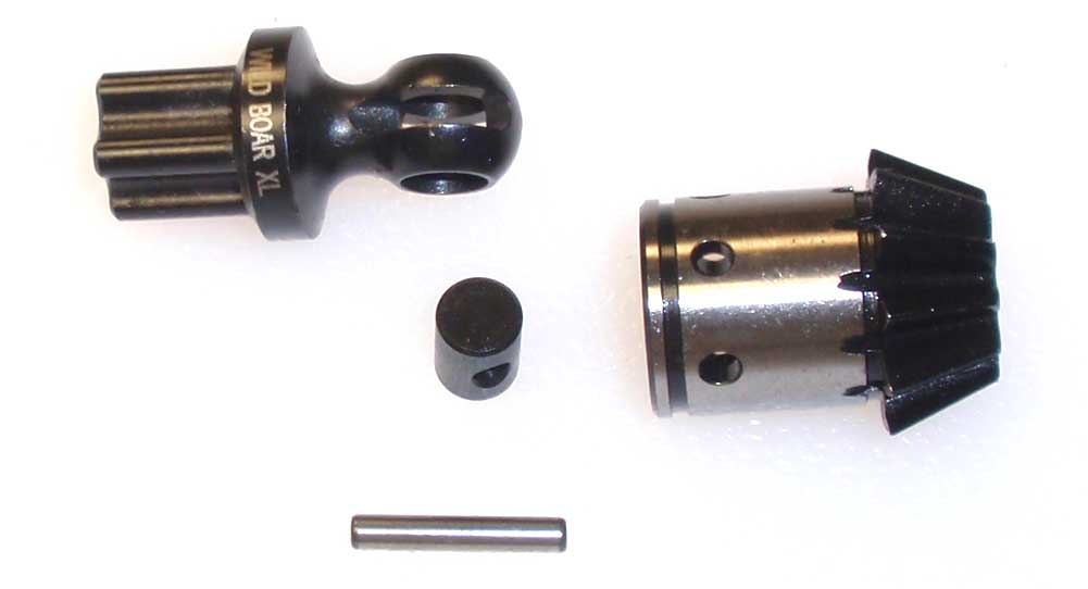
Let’s start the rear axle by assembling the rear input shaft. Like the front, insert the CVD barrel into the joint and slide it into the 11T gear. Slide the pin through the holes in the gear and input barrel. Make sure to use a good amount of black grease to keep things lubricated.
Step 2:
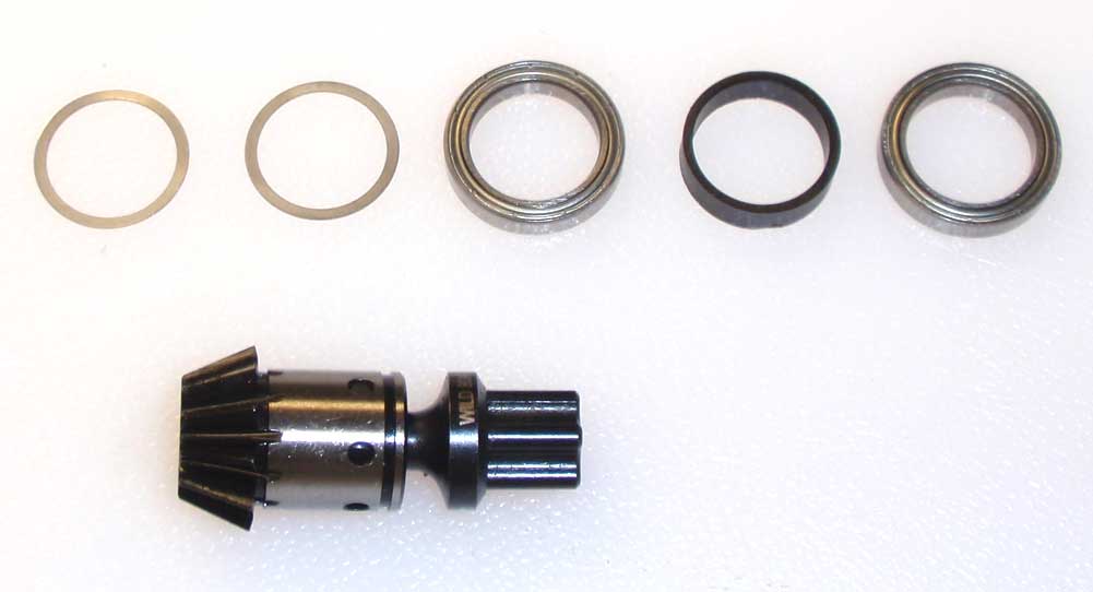
Slide a pair of 15×18 washers followed by a 15×21 bearing, plastic spacer and second 15×21 bearing. These parts capture the CVD pin and prevent it from falling out.
Step 3:
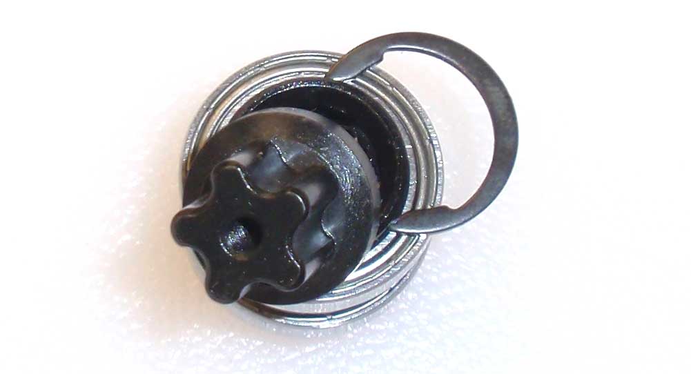
Set the gear assembly up on it’s side and slide the C-clip into place. Press the bearings/spacer/shims down firmly to seat them and, using needlenose pliers, carefully snap it into the groove, just like the front assembly.
Step 4:
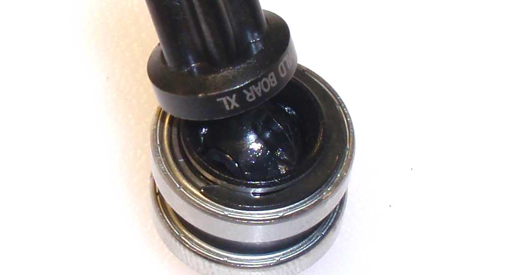
Here is what the assembly should look like. Just make sure the clip is completely seated in the groove.
Step 5:
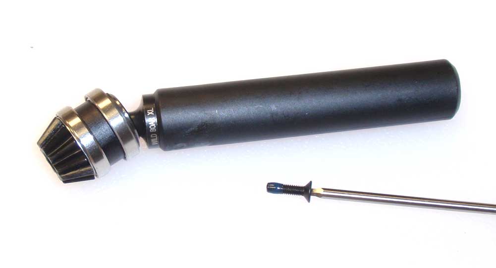
Mate the splined CVD to the splined end of the slider shaft. Press together firmly to make sure it’s completely seated and secure with the M3 flathead screw. A drop of threadlocking compound will help prevent this screw from backing out.
Step 6:
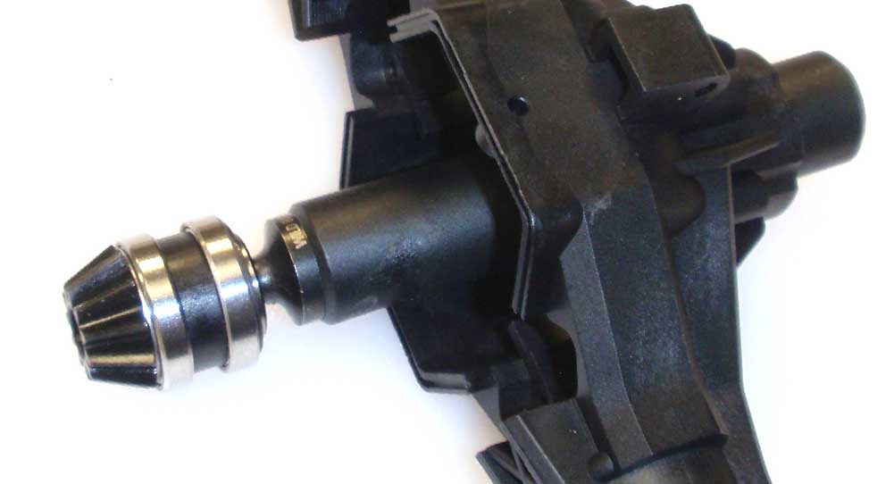
Slide the slider assembly through the rear axle housing as shown and firmly press to completely seat the bearings into the recess.
Step 7:
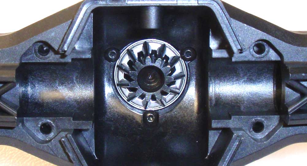
Secure the slider assembly with the 3 M2.6 screws. Like the front, make sure that the slider assembly is completely seated.
Step 8:
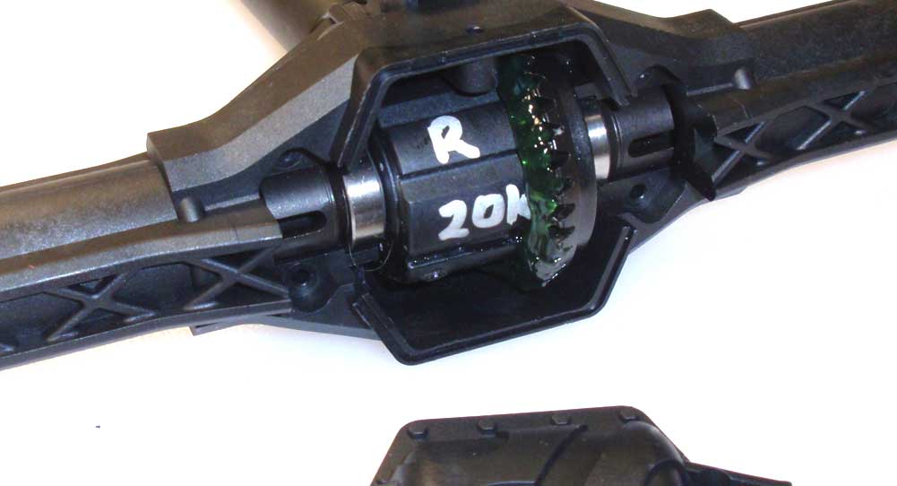
Grab your differential and apply a good amount of the supplied grease to the gears. Press the diff into the housing and screw the rear axle cap into place.
Step 9:
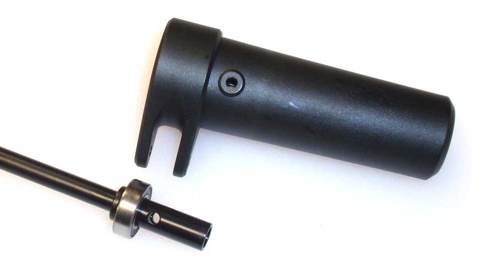
The instructions have you inserting both drive axles into the rear housing, but I actually found it easier to build them a little different. Start by sliding a 8×16 bearing onto each axle and then firmly pressing it into the outer carrier to square it up and completely seat it.
Step 10:
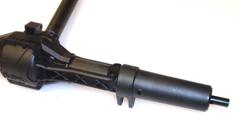
Now slide that assembly into the rear axle housing. While pressing, rotate the drive axle to key the dogbone to the diff inside. Note the orientation of the link pickups to the rear axle; they should be pointing down.
Step 11:
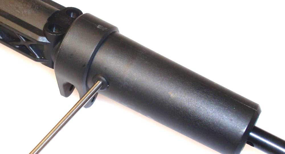
Secure the outer carriers with the M3 screws. I used a small driver to align the holes prior to installation.
Step 12:
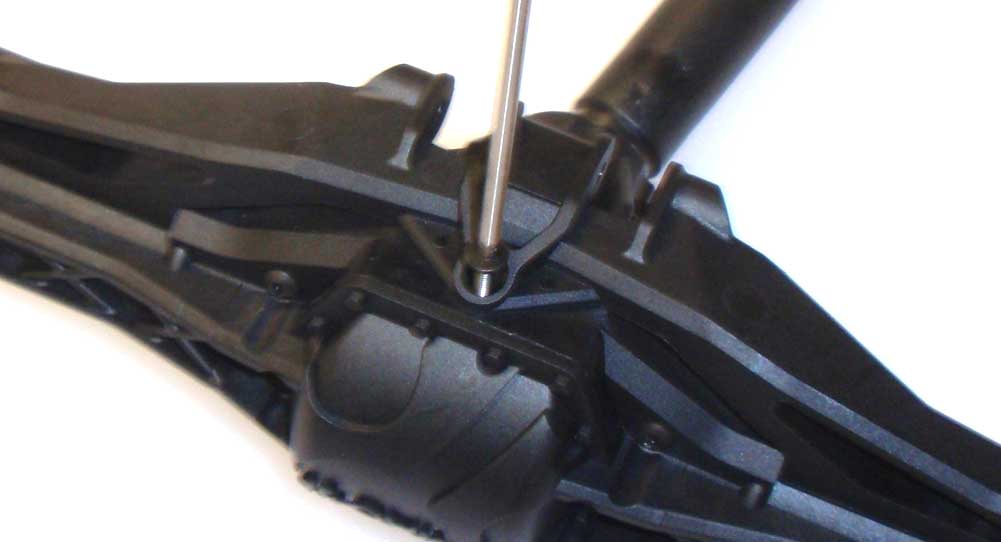
Attach the rear axle brace. Getting this piece to snap into place was a major pain. I found it easiest to install one end, secure with the two M3x25mm (only engage them about 5 or 6 threads in) and then flex the piece to pop the other end in. You can then insert the other M3x25mm screws and tighten down. Install the M3x10mm screw last.
Step 13:
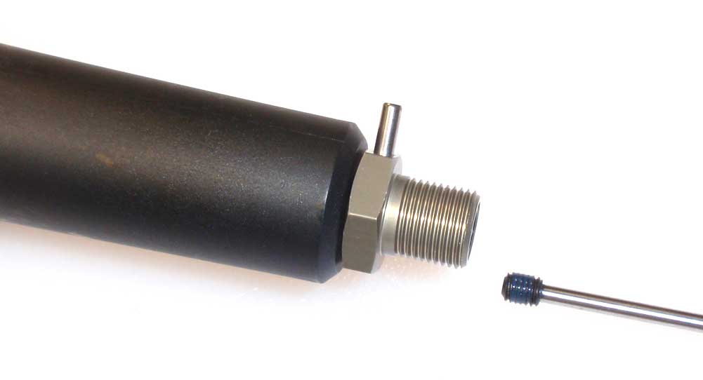
Slide the aluminum hexes onto the axles, insert the drive pin and secure with the M5 setscrew. Threadlocking compound is highly recommended here.
Once complete, rotate the slider axle a few times to make sure everything rotates smoothly. Time to move on to the front suspension.
Axial Yeti XL Online Build – Part 5
Axial has outfitted the Yeti XL with an independent front suspension that uses some beefy parts. CVDs are also a standard item as are the metal pins to capture the steering blocks.
Build Notes:
• Pay close attention to the left and right steering parts. It’s easy to get them mixed up.
• Be extra careful not to overtighten the set screws in Step 59.
Step 1:
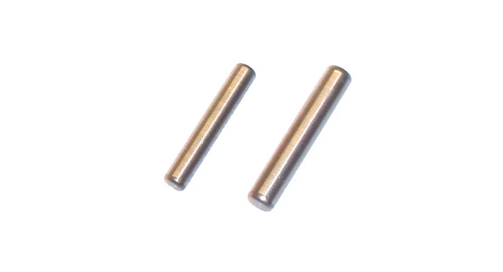
Before we start assembling, take a look at these two pins. The one one the left is used in the CVDs; the one on the right is used on the axles. Grab the smaller ones first.
Step 2:
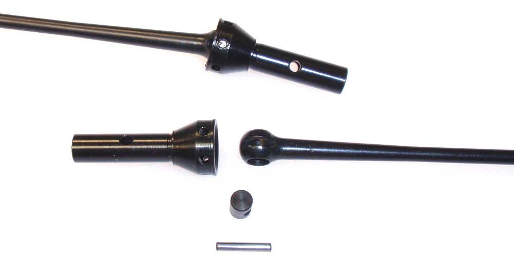
Assemble the CVDs like we’ve done so far with all the others; barrel in the ball, ball in the axle and the pin through both. Don’t forget to add the black grease for lubrication.
Step 3:
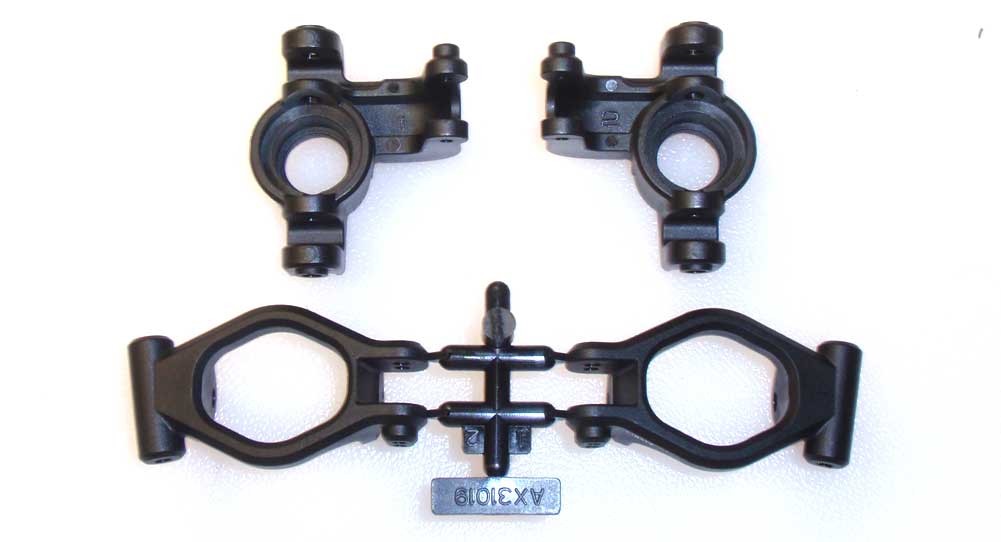
Before we move on, we also need to identify the left and right steering pieces. The steering knuckle/caster block on the left are for the left side, the steering knuckle/caster block on the right are for the right side of the Yeti. Don’t get them mixed up.
Step 4:
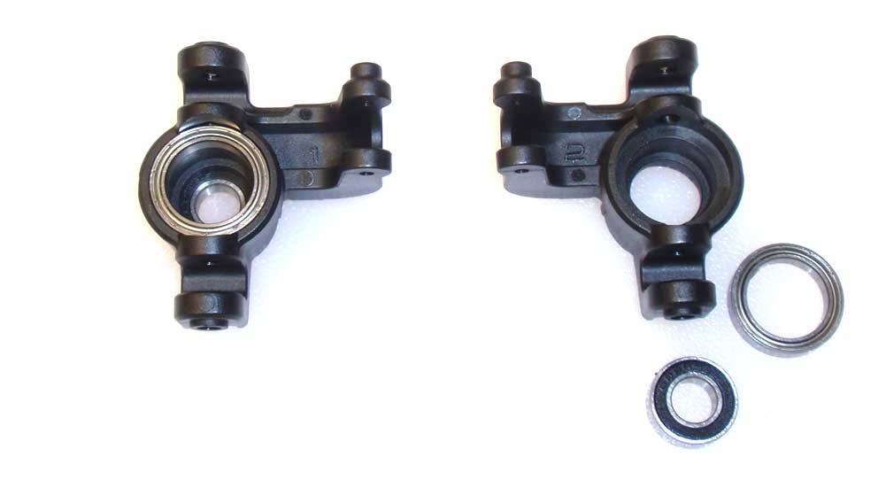
Moving on … press the bearings into the steering block.
Step 5:
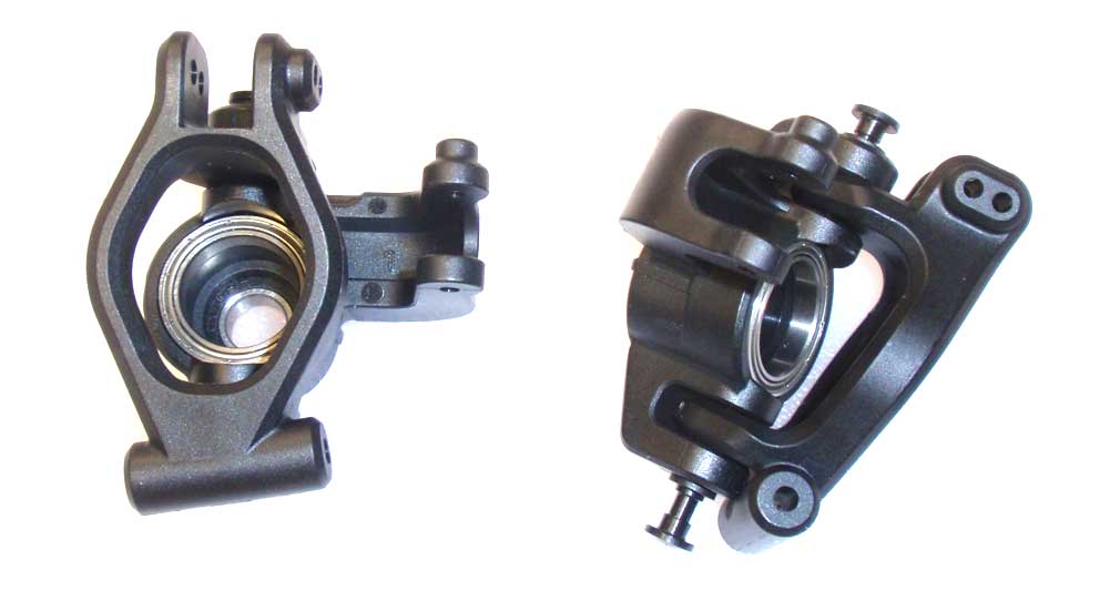
Assemble the left and right steering assemblies as shown. Slide the metal pins in place to capture the steering blocks.
Step 6:
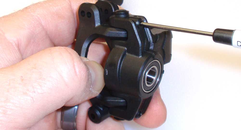
CAREFULLY screw the M3 setscrews (top and bottom) into the steering block. Tigthen SLOWLY until you feel it make contact with the metal pin, then give it another 1/4 turn. Do not overtighten or you’ll easily strip out the plastic. Give the metal pin a little tug to make sure the set screw has it secured in place.
Step 7:
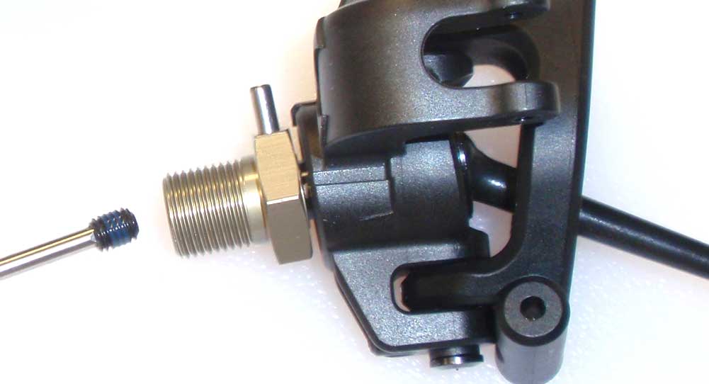
Slide the CVD into the steering assembly. Press the wheel hex into place, slide the larger pin through both and secure with the M5 setscrew. Use some threadlocking compound here.
Step 8:
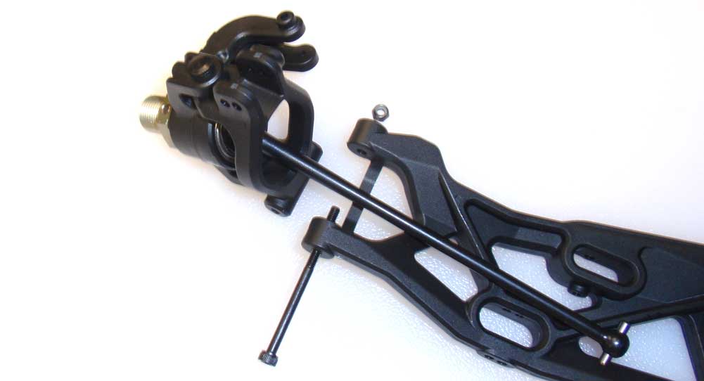
Attach the left steering assembly to the left suspension arm and the right steering assembly to the right suspension arm. Do not overtighten the long M3 screw. The picture is showing the right suspension assembly.
Step 9:
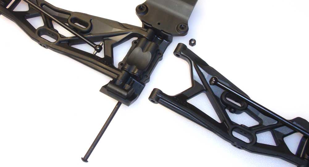
Align both front arms and attach them to the bulkhead with the hinge pins/locknuts. Do not overtighten here, either. Holding on to the locknuts is a bit tricky, so have some needlenose pliers handy to help.
Step 10:
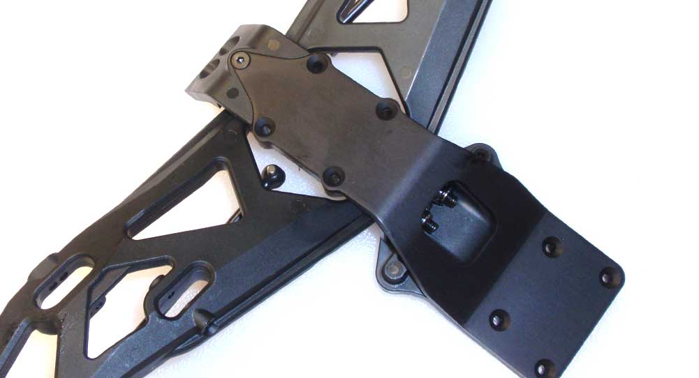
Before attaching the front gearbox, flip the bulkhead over and attach the skid plate at the front-most point. You can also see those pesky little locknuts as well.
Step 11:
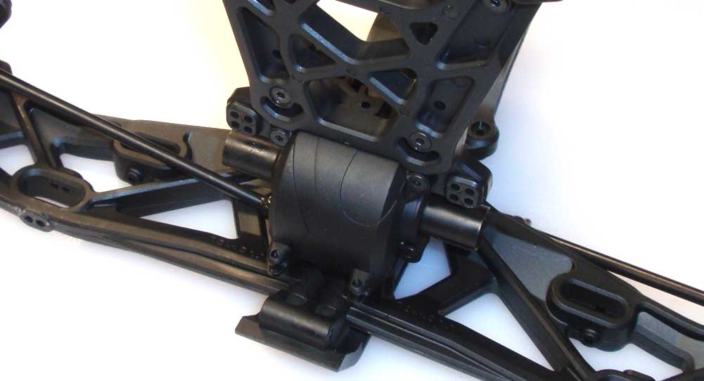
Flip the assembly back over and attach the front gearbox to the bulkhead. Don’t worry about getting the axles into the outdrives just yet.
Step 12:
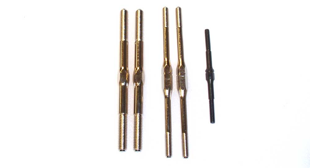
Time to work on my favorite part; turnbuckles (NOT!). The two turnbuckles on the left are for the front camber, the two in the middle for the steering and the black one is the drag link.
Step 13:
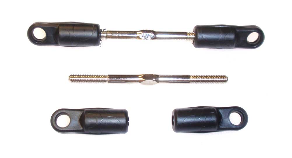
Build two camber links. The length of 45mm in the center is a good starting point.
Step 14:
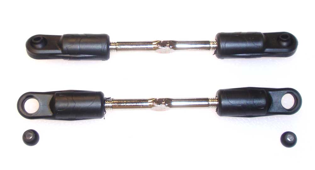
Pop the balls into the rod ends.
Step 15:
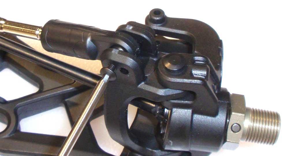
Attach the camber links to the caster blocks. My manual showed one side going into the inside hole, the other to the outside hole. Use the inside hole.
Step 16:
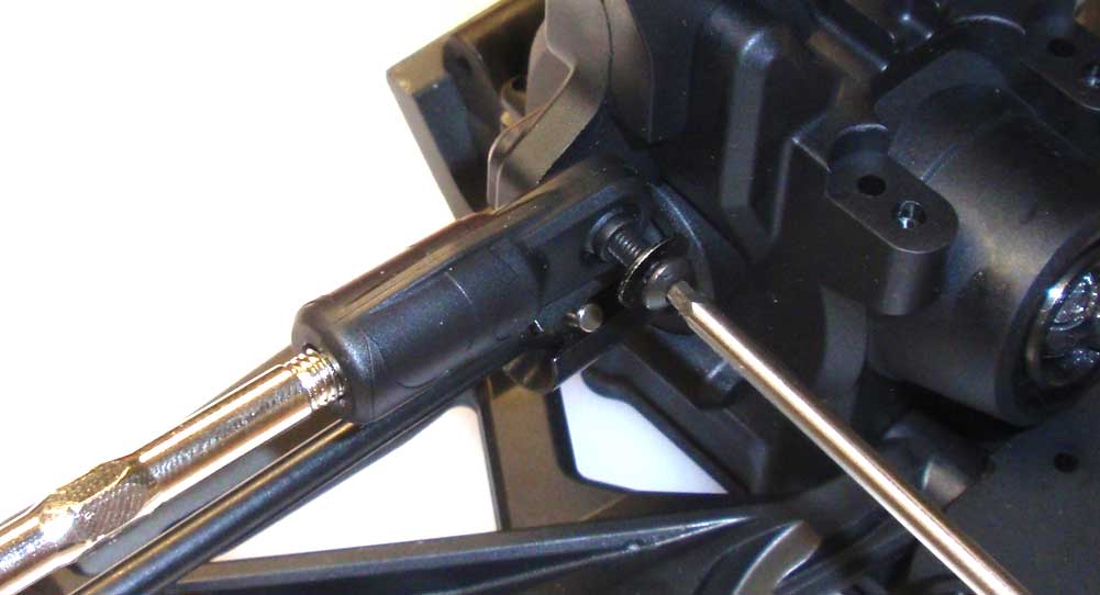
Key the CVD to the diff outdrive and then attach the other end of the turnbuckle to the upper/outside hole on the tower. Don’t forget the 5mm washer.
Step 17:
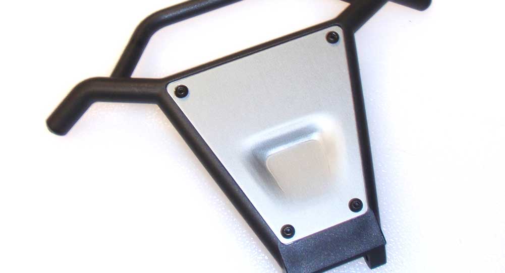
Attach the aluminum skid to the front bumper.
Step 18:
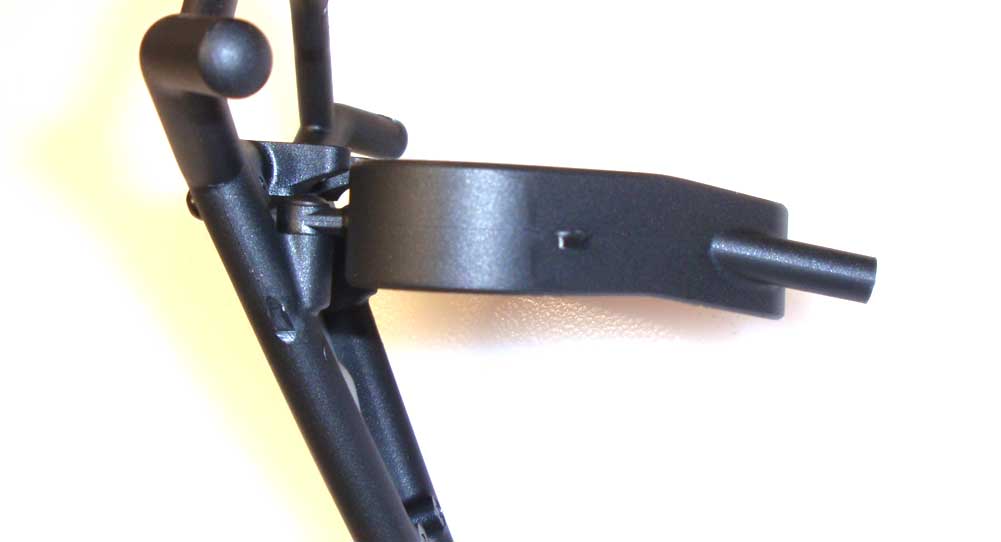
Attach the brace to the front bumper. I’ve shown a side view so you can see the orientation of the brace.
Step 19:
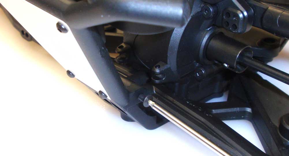
Attach the front bumper to the bulkhead…
Step 20:
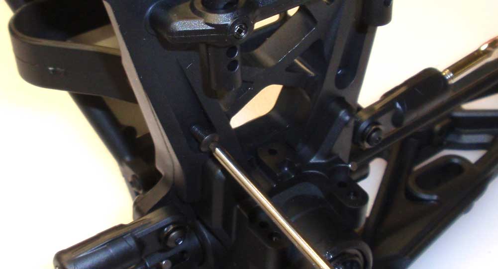
…and then to the shock tower.
There you have it; the front suspension is complete! Time to build the steering and get all of it installed to the chassis.
Axial Yeti XL Online Build – Part 6
The Yeti XL uses a dual-bellcrank steering setup that rolls on a nice set of bearings. It has an integrated servo saver as well as adjustable links for toe.
Build Notes:
• If you have an older manual, you’ll notice that the part number for the rod ends in Step 80 is AX80092[4]. You won’t find those parts on that tree. The correct part number should be AX31032.
Step 1:
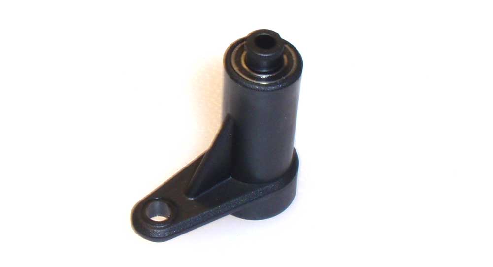
Press a 6×10 bearing into each end of the right bellcrank arm, then slide one of the steering posts into place.
Step 2:
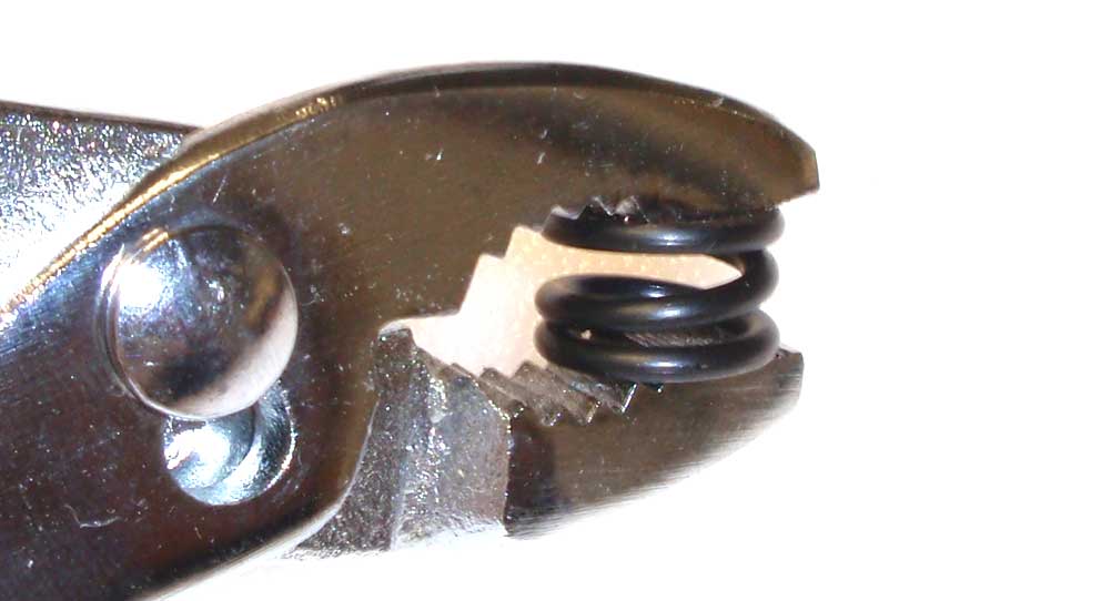
Pre-compress the servo saver spring a few times to settle it.
Step 3:
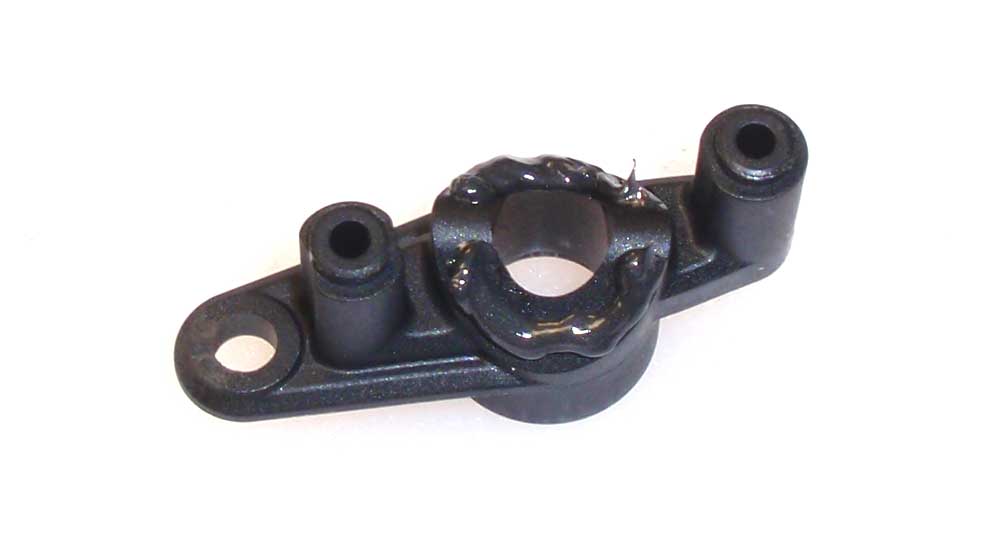
Anyone who follows my builds recognizes this little trick. Application of a little black grease on the servo saver section helps prevent the two plastic pieces from getting gritty and possibly sticking. Only a little on one side of the servo saver is necessary.
Step 4:
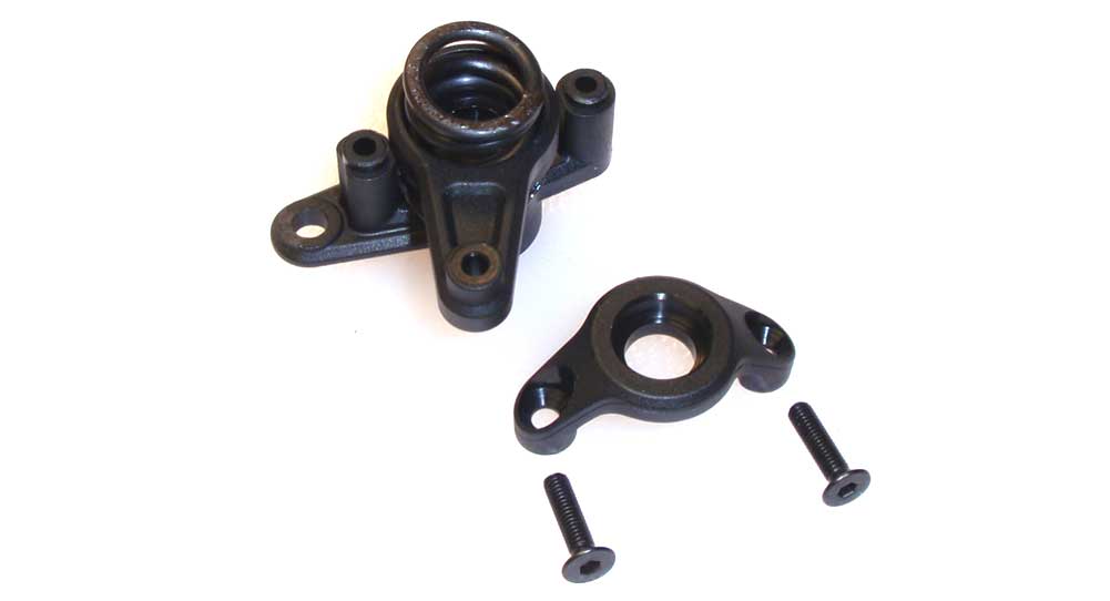
Mate the upper and lower servo saver arms together and set the spring into place. Secure the spring with the cap and screw into place. Press a 6×10 bearing into each end followed by the other steering post.
Step 5:
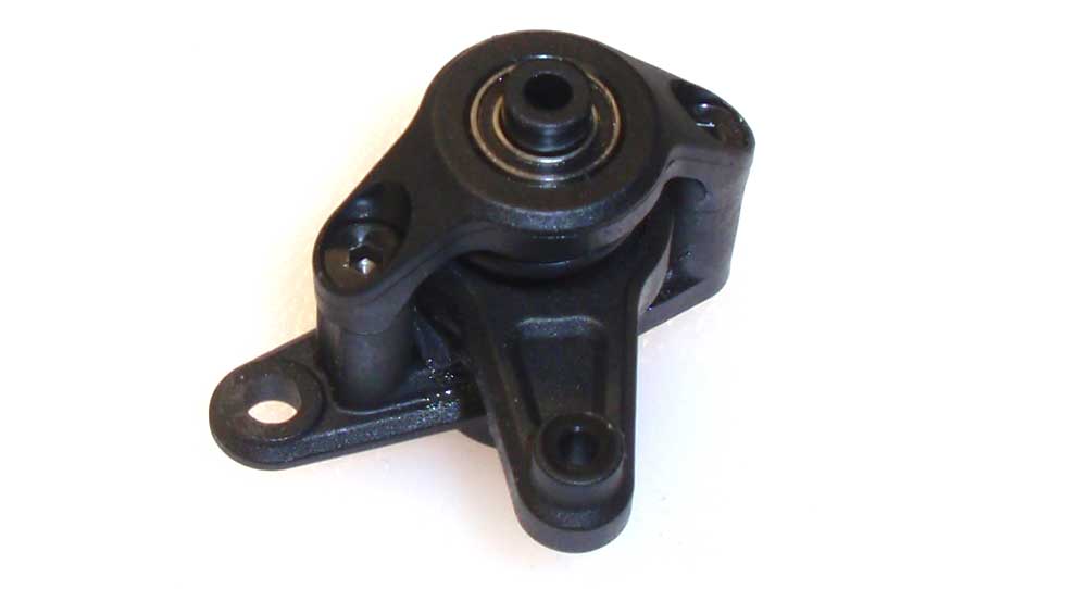
Here is what you final servo saver assembly should look like.
Step 6:
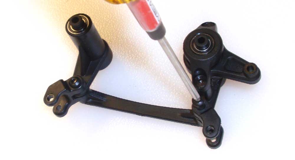
Attach the left and right steering bellcrank arms to the center drag link. Do not overtighten; make sure everything swings back and forth easily.
Step 7:
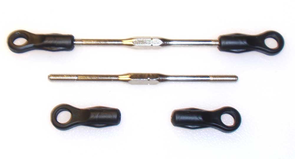
Build two steering links. The 62mm gap is a good starting point. If you can’t find the rod ends, you didn’t read the Build Notes for this build step. Scroll to the top and check them out.
Step 8:
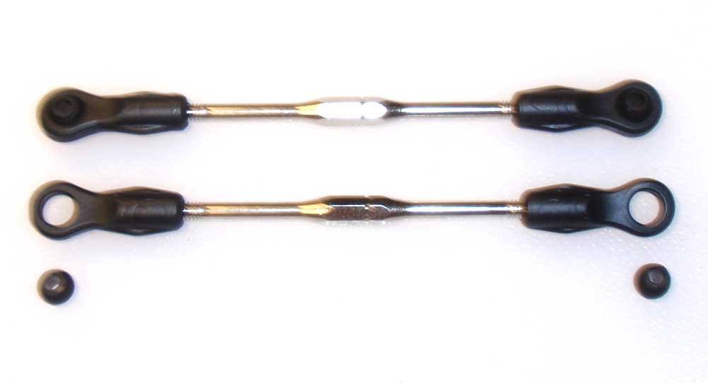
Pop the plastic balls into the rod ends.
Step 9:
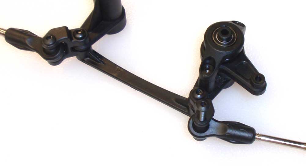
Attach the steering links to the drag link. Again, do not overtighten.
Step 10:
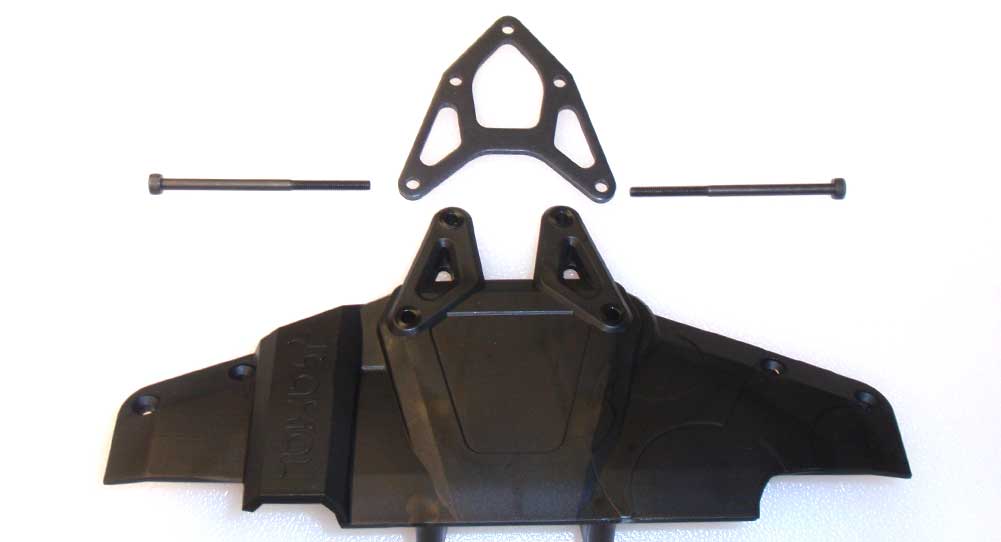
The manual shows us attaching the steering system to the chassis and the steering links to the steering knuckles, but that became quite the mess to deal with. We’re going to deviate slightly from the manual to make life a little easier. Start by sliding the two M3x50mm screws through the metal top brace, then the top deck.
Step 11:
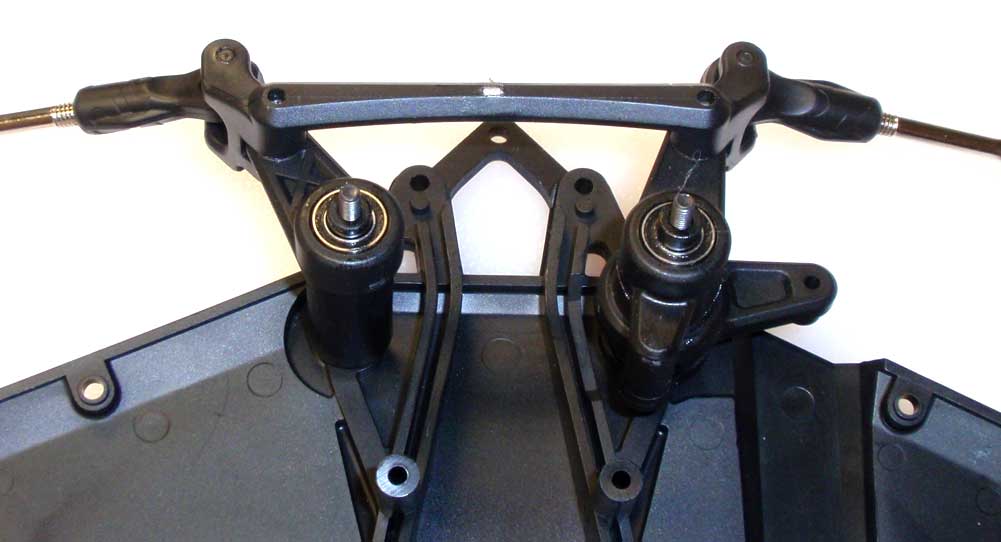
Flip that assembly over and slide the steering system into place.
Step 12:
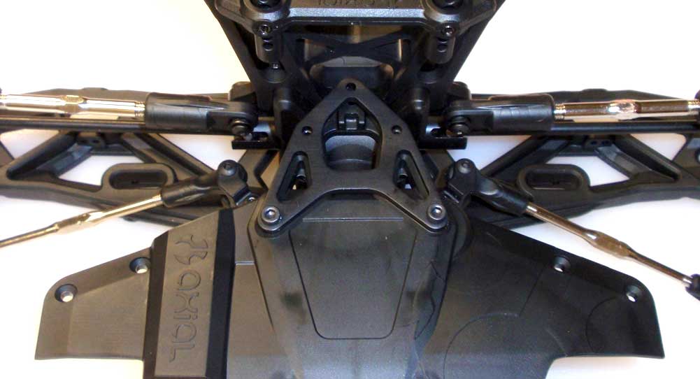
While aligning the screws in the top deck to the mounting holes in the front suspension, lower the front suspension onto the overturned steering setup. Hold together, flip over and start tightening the two 50mm screws. Do not tighten down all the way yet. You want to get them in about 1/2 way.
That steering assembly probably took alot out of you, so take a quick break before we start assembling the chassis.
Axial Yeti XL Online Build – Part 7
The chassis on the Yeti XL is a quite the marvel of molding. It’s got pockets and channels molded in all over the place. It’s also a simple slip-and-fit design, sort of.
Build Notes:
• Patience is key for the first step or two when mating the chassis to the front suspension. Take your time and it will work itself out.
Step 1:
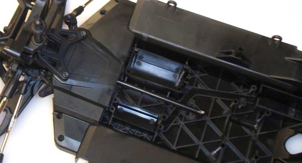
The first thing we need to do is slip the chassis tongue between the top deck and lower skid plate on the front suspension clip. In the last step, I had you only screw the long 50mm screws in a short ways … now you’ll see why. Start by slipping the front CVD through the channel in the chassis. Now pull the top deck apart, SLOWLY, from the front clip, making sure you don’t dislodge the steering system. Slide the chassis tongue into place.
Step 2:
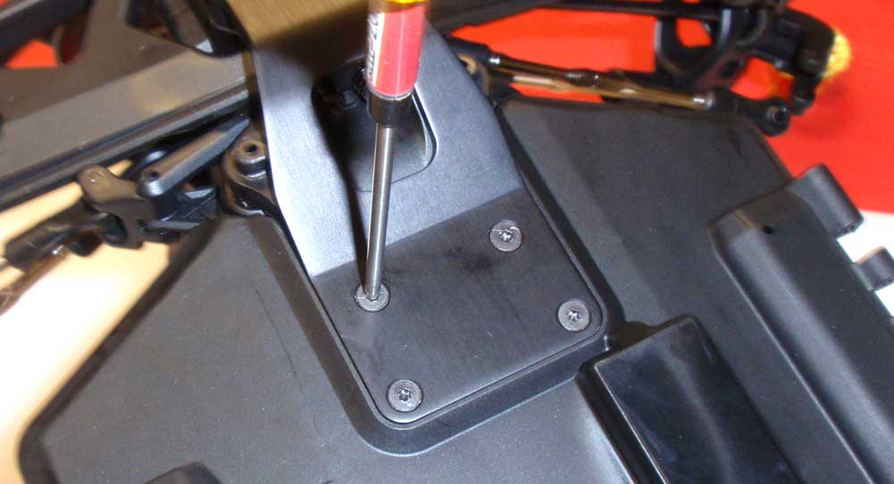
There are some alignment issues you’ll need to work around, so here’s the best way I found to do this. After you’ve squeaked the chassis into place, insert the lower skid plate screws. Don’t tighten them up all the way quite yet.
Step 3:
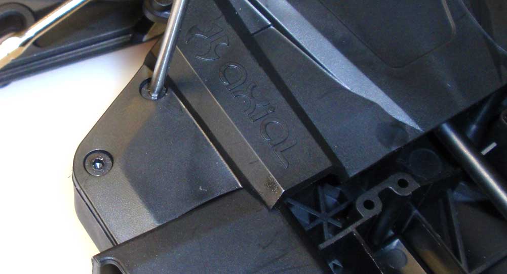
Pop the side ‘wings’ into place and insert the screws here. Don’t tighten them quite yet either.
Step 4:
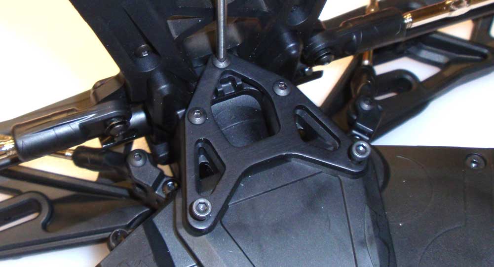
Insert the three M3x15mm screws and flex the assembly a bit to make them fit. If you’re having trouble, loosen the screw a little from Steps 87 and 88. This might seem odd but trust me, this is the easiest part of the chassis to flex. Once you get them started, go ahead and tighten down all the screws from 87, 88 and this step.
Step 5:
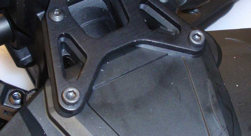
Tighten these screws last. Just make sure you haven’t dislodged the steering system.
Step 6:
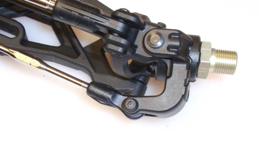
Finally, attach the turnbuckles to the steering knuckles.
Now see, that wasn’t so hard, was it? Give yourself a pat on the back … you’re about half-way through the build!
Axial Yeti XL Online Build – Part 8
Since this is a kit, I had the luxury of outfitting the Yeti XL with whatever electronics I wanted to. I’m not going to be playing nice with this rig, so I wanted gear that I knew would survive lots of full-throttle. Thanks Futaba, Castle Creations and Maxamps for your contribution to this bonzai build.
Build Notes:
• The Yeti XL isn’t for the feint of heart; it’s also not a place for puny electronics. I would suggest installing some pretty stout equipment or you’ll be doing it more than once.
• Make sure, when installing, that the waterproof rubber wire gaskets seat correctly into the receiver box. The last thing you want is this 15lb behemoth barreling away from you at 60+mph!
Step 1:
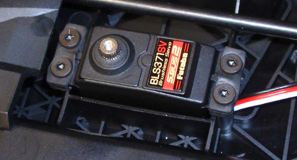
This is a beast of a rig that sports some pretty hefty tires, so I needed a servo that’s going to be able to handle a major workout. That said, nothing other than a Futaba servo would fit the bill; their BLS371SV was mounted to the chassis.
Step 2:
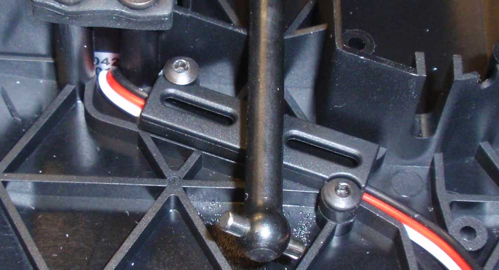
Feed the wire under the front CVD and capture it with this cool little lead cover.
Step 3:
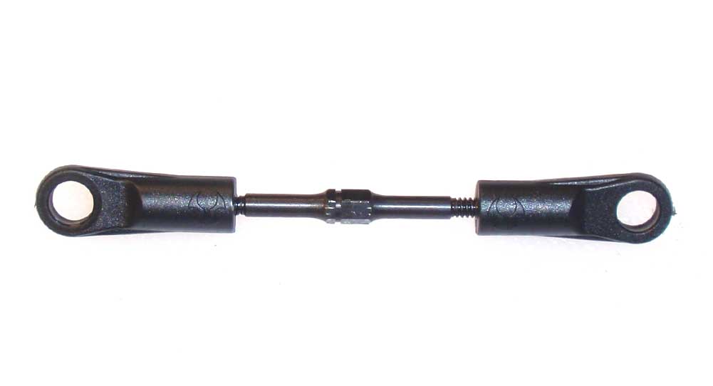
Build the drag link. 30mm is a good starting point.
Step 4:
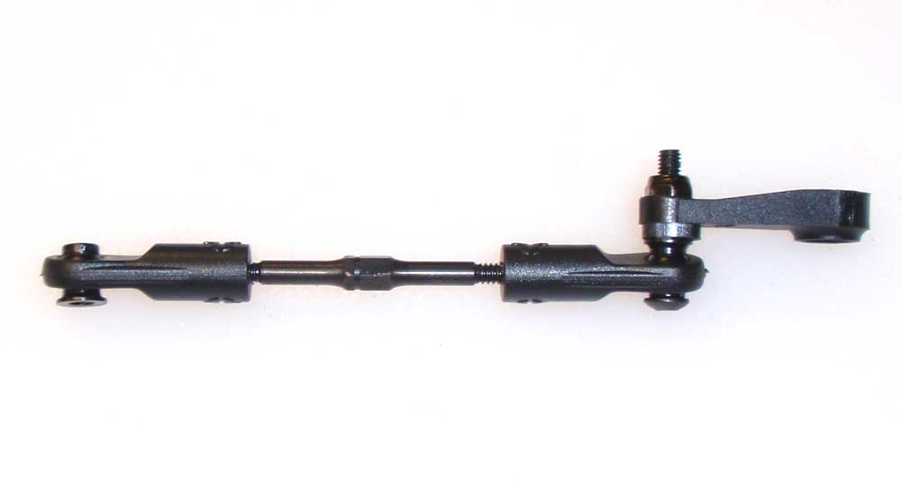
Assemble the steering link using the correct horn for your servo. Notice the direction of the ball inserts.
Step 5:
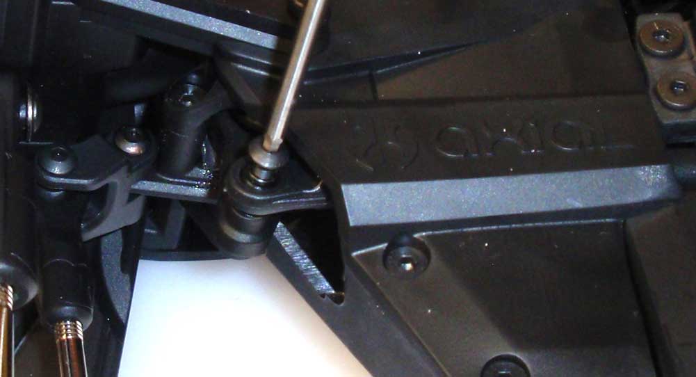
Feed the steering link through the opening and attach it to the servo saver arm.
Step 6:
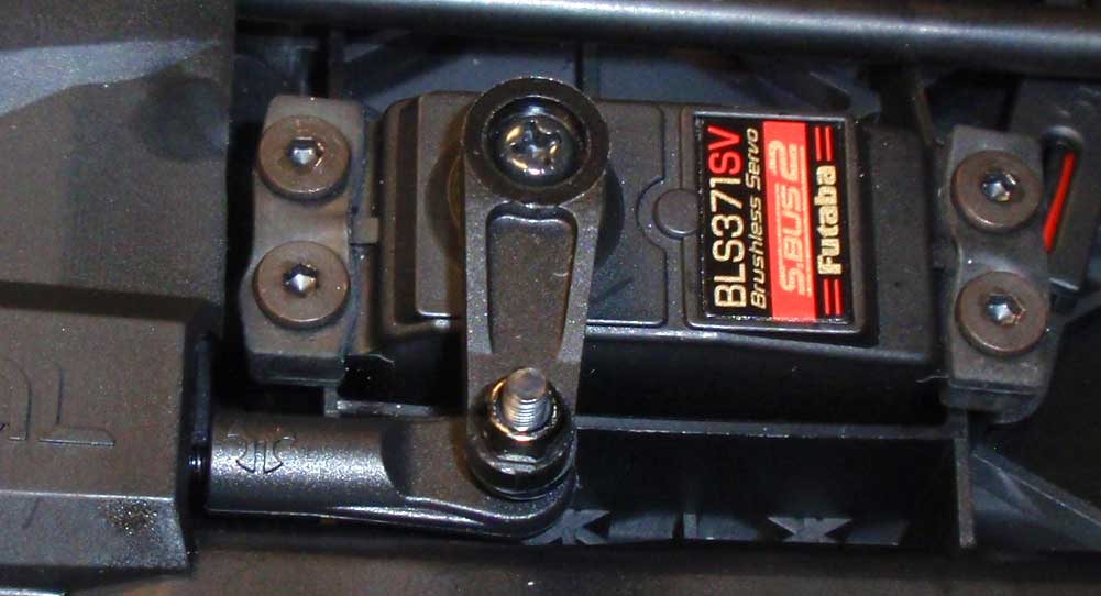
Attach the servo horn to the servo. Doing it in this order makes it easier to hold on to when attaching it to the servo saver arm.
Step 7:
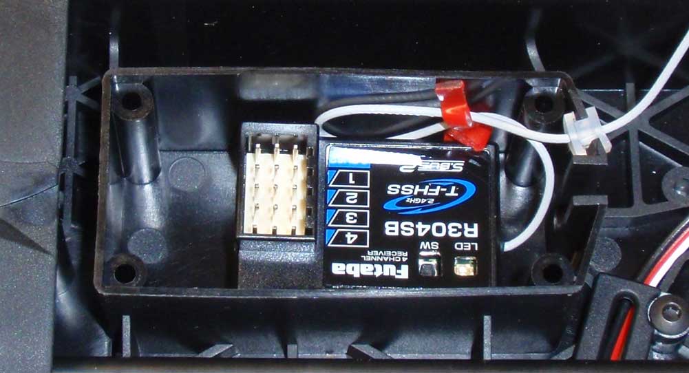
Tape your receiver into the receiver box. Feed the antenna through the small, rubber water sealer and press the sealer into the groove in the box.
Step 8:
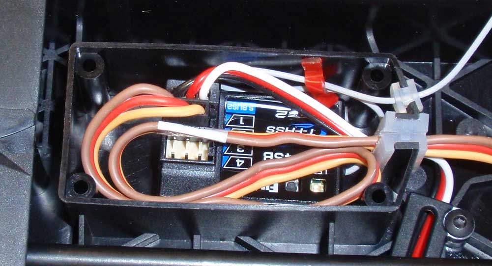
Take your servo and ESC wires and slide them through the large, rubber water sealer, then press the sealer into the groove in the box. Pull as much of the wire into the box as you can to avoid having a rat’s nest outside of the box. Use the AX31021 spacer to fill the top hole in the water sealer.
Step 9:
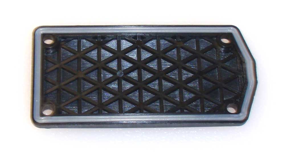
Press the waterproofing gasket into the lid of the receiver box.
Step 10:
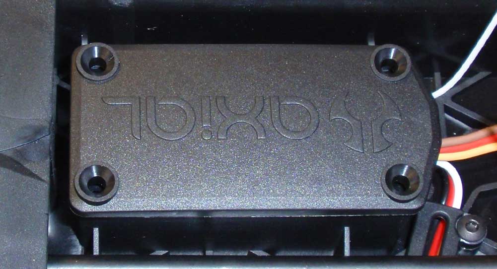
Carefully place the lid on top of the receiver box. Press down firmly to seat it.
Step 11:
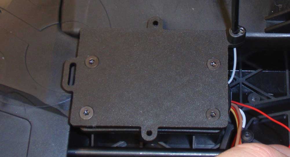
Set the ESC mount on top of the receiver box and screw into place. Feed the antenna wire up through the mount and into the tube. Secure the tube with the M3 set screw.
Step 12:
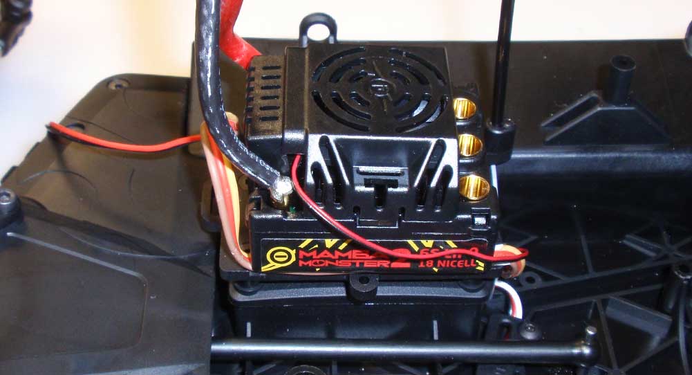
Apply a hefty amount of double-sided tape to your ESC and press onto the mount. This is also a good time to affix your on/off switch.
Electronics in and ready to go. The next step involves the heart of the beast; the transmission!
Axial Yeti XL Online Build – Part 9
Sitting in the center of this monster is the heart of the Yeti; a beefy 3-gear transmission that includes an external slipper clutch designed to take some major punishment.
Build Notes:
• The Yeti comes equipped with a slipper that includes a pair of metal slipper pads as well as a pair of flexible pads. Toss the flexible ones aside; we need the meat of the metal ones for the XL.
Step 1:
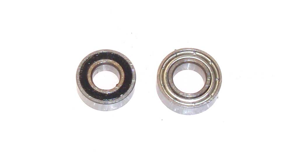
Before we begin, take a look a the two bearings we’ll be using during this step. The 5×11 bearing on the left will be used on the top and center shaft; the 6×12 bearing on the right will be used on the lower output shaft.
Step 2:
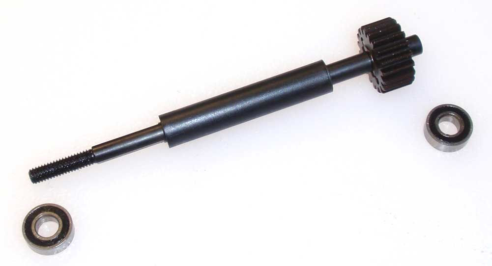
Insert a 2×10 pin in the top shaft followed by the top shaft gear. Slide the long plastic spacer over the top shaft and install a 5×11 bearing on each end.
Step 3:
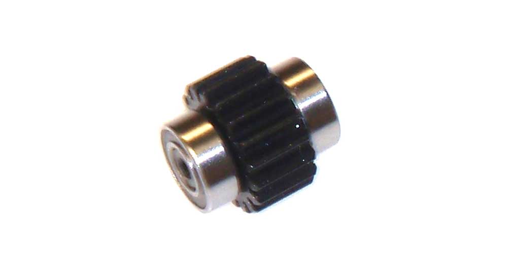
Insert a 5×11 bearing on each end of the center idler gear.
Step 4:
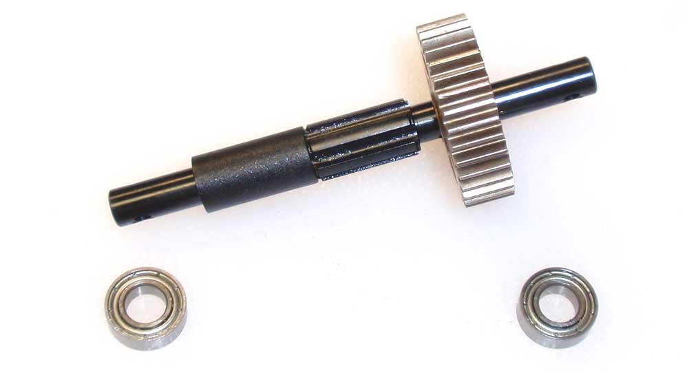
Insert a 2.5×12 pin into the output shaft followed by the 34T main gear. Slide the short plastic spacer over the output shaft, then install a 6×12 bearing on each end.
Step 5:
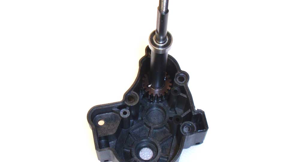
There is a method to installing the gears into the transmission case, so start by pressing the top shaft into place.
Step 6:
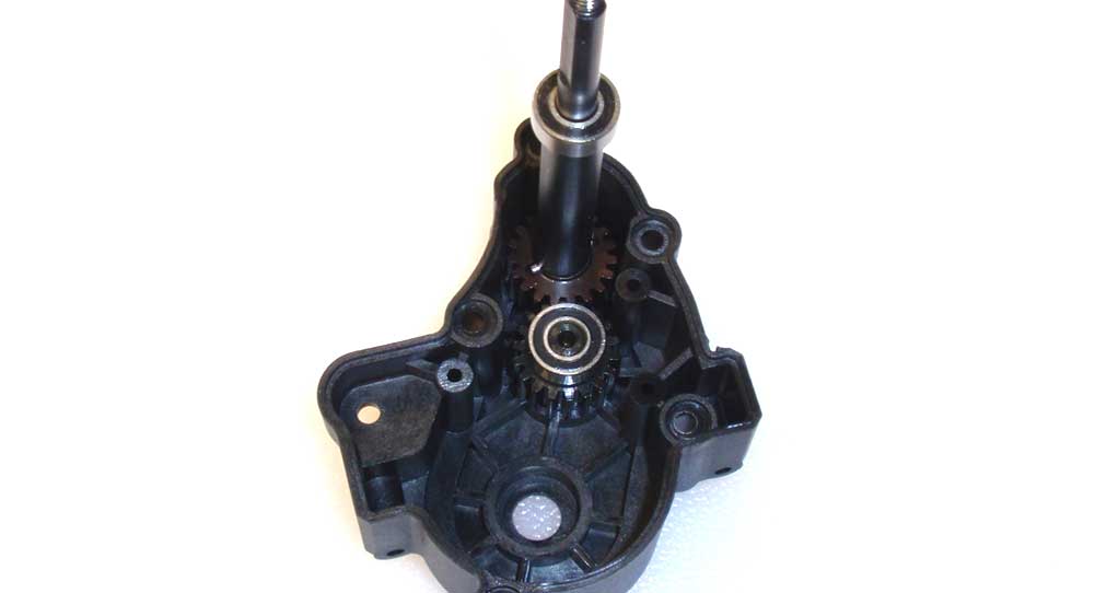
Next, press the idler gear into place.
Step 7:
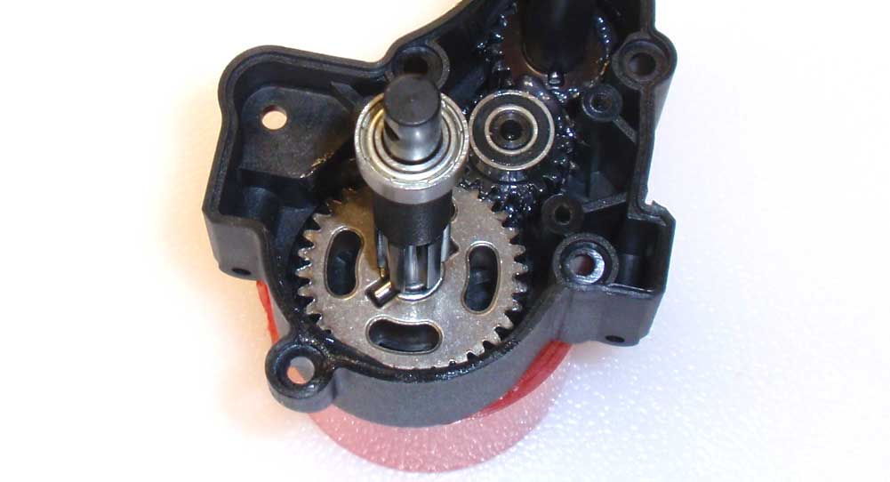
Apply a liberal amount of the included grease to the main gear and press the output shaft assembly into place. Rotate the output shaft a few times to spread the grease around. Finally, install the idler gear ‘cap’ and screw in place. Do not overtighten!
Step 8:
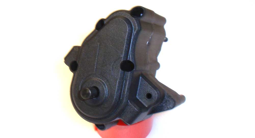
Mate and screw the two transmission halves together. Make sure the gears and bearing seat correctly before buttoning it all up.
Step 9:
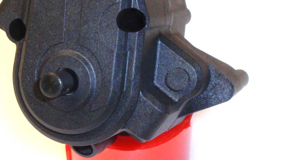
Press the rubber plug into place.
Step 10:
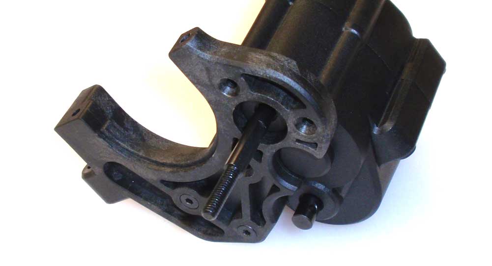
Attach the plastic motor mount to the transmission.
Step 11:
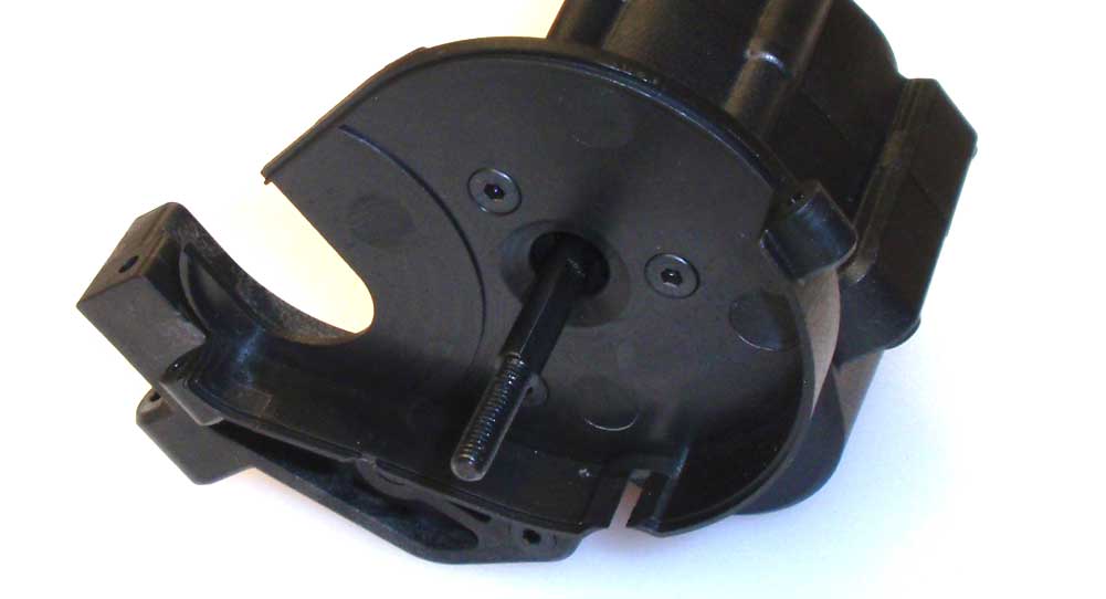
Attach the inner gear cover to the motor mount.
Step 12:
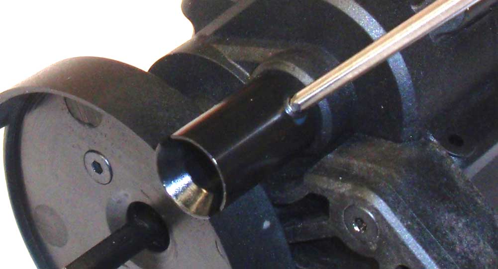
Slide the drive cup onto the output shaft and secure with the M4 setscrew. A drop of threadlocker is suggested here.
Step 13:
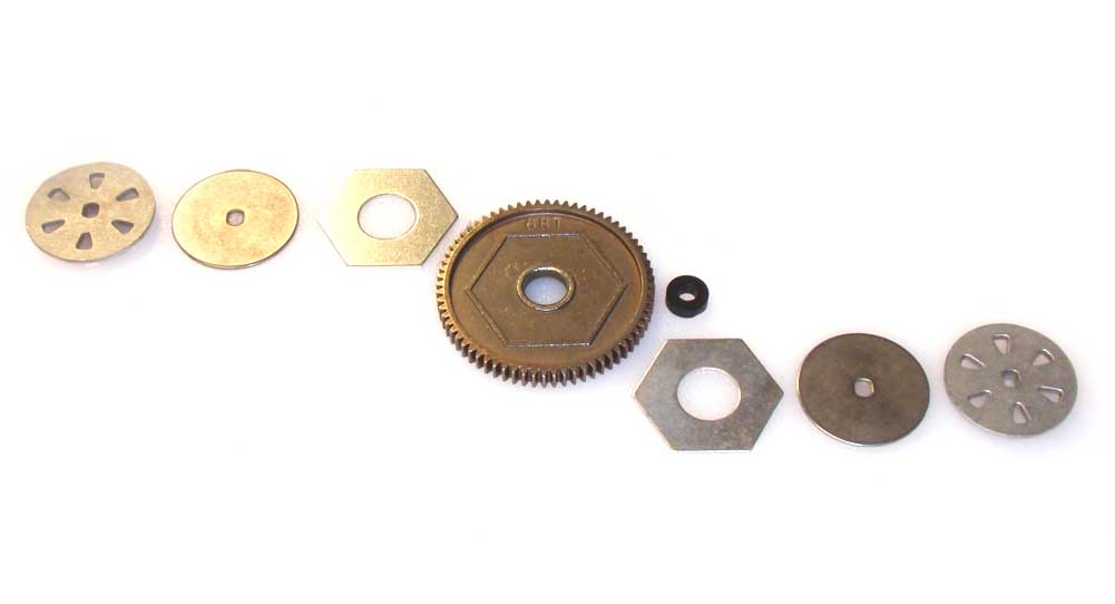
There’s quite a few parts that go into the slipper assembly. I’ve laid them out to show you how everything goes together.
Step 14:
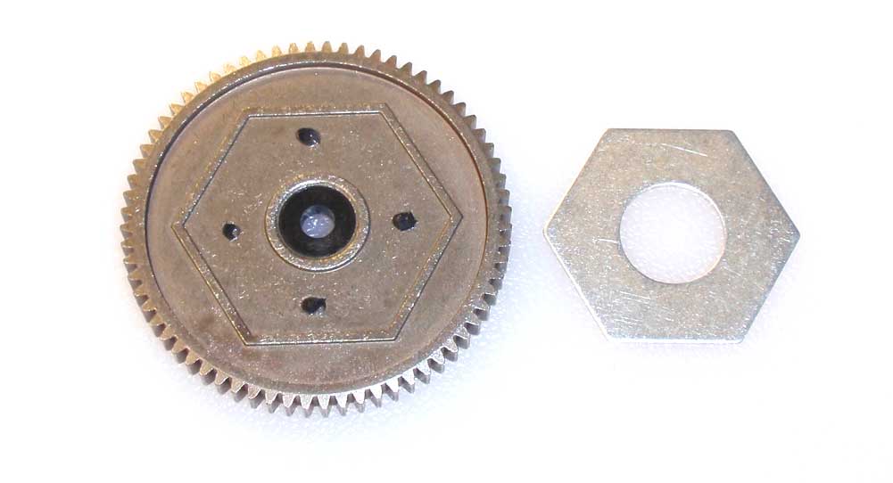
Press the plastic spacer into the spur gear and attach both slipper pads. I used a few small drops of black grease to hold the pads to the gear.
Step 15:
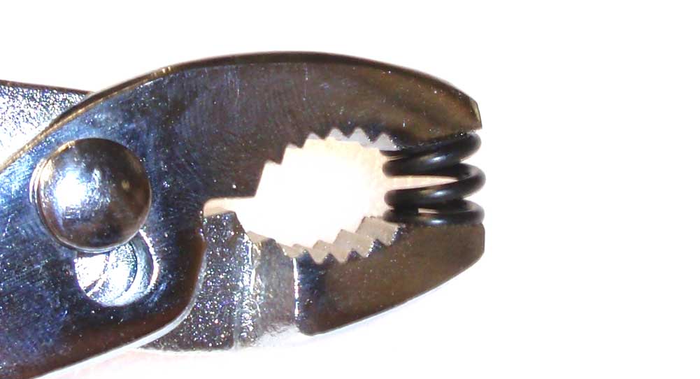
Pre-compress the slipper spring a few times to settle it in.
Step 16:
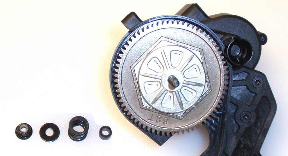
Slide the inner slipper hub on the top shaft followed by the slipper washer, spur gear assembly, another slipper washer and then the outer slipper hub. Install the plastic spring centering spacer, the slipper spring, a 4×11 washer and the slipper nut.
Step 17:
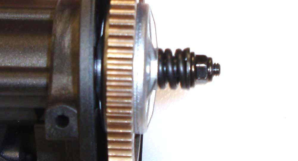
Tighten it down all the way and then back it off until there is about 2mm of thread showing.
Step 18:
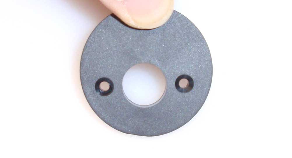
Assemble the motor mounting plate. It actually goes together in a few different ways but just make sure the screws holes align as shown in the picture.
Step 19:
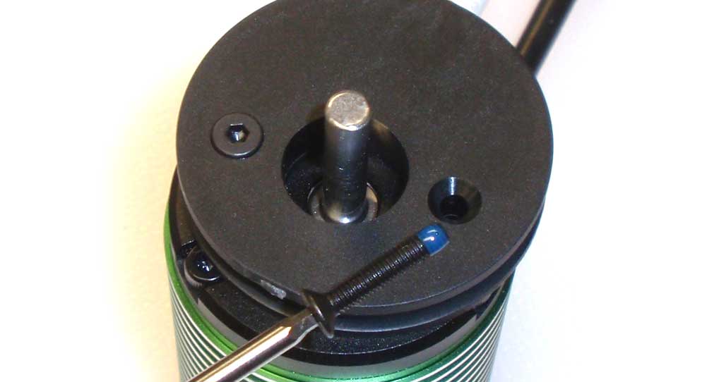
Attach the motor mount plate to the motor. A drop of threadlocker on the screws will help prevent them from coming loose during your ham-fisted playtime.
Step 20:
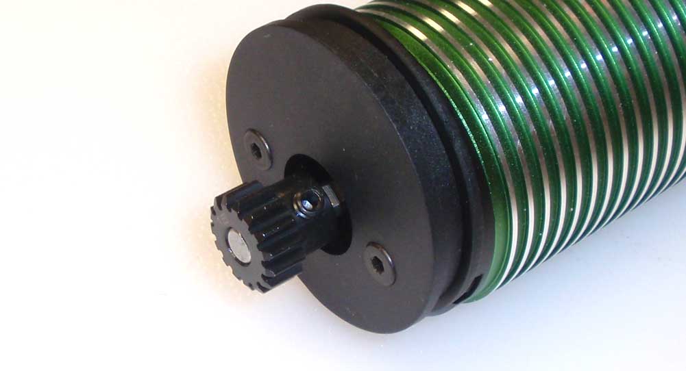
Install the supplied pinion, making it flush with the end of the shaft. We can adjust it, if neede, in the next step. Threadlocker on the set screw is suggested.
Step 21:
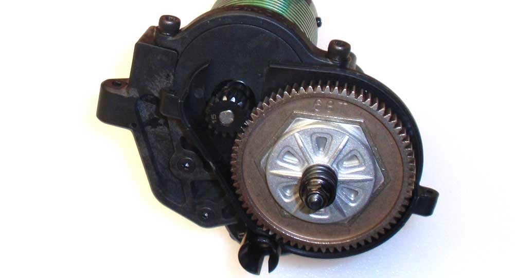
Slide the motor assembly into the grooves in the motor mount and capture with the plastic cap. Once you’ve set the gear mesh, tighten the screws down good and tight. You can now adjust your pinion in or out to match the spur gear.
Step 22:
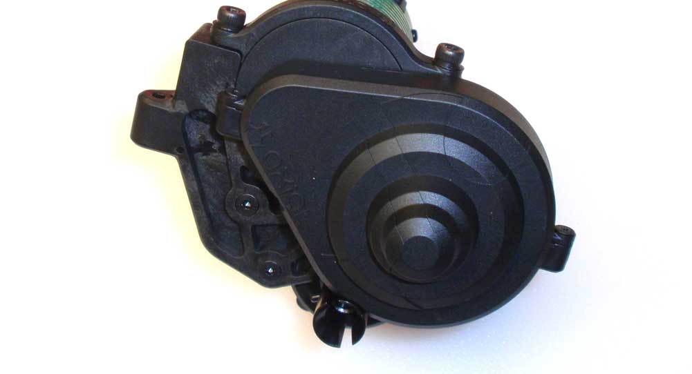
Install the gear cover.
Step 23:
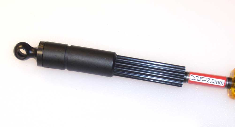
Attach the CVD stub to the slider shaft. Use a dab of threadlocker on the M3 screw.
Step 24:
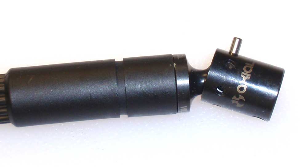
Build this axle like you’ve done with the other CVDs; barrel into the ball, cup over the ball and capture with the pin. Don’t forget the black grease.
Step 25:
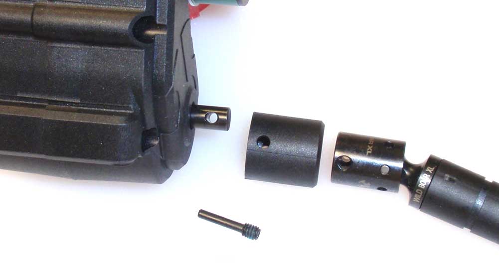
Slide the CVD assembly into the plastic cap. This cap is used to retain the pin you installed in the last step. Slide this assembly onto the outpt shaft and secure with the M4 set screw. Don’t forget a dab of threadlocker.
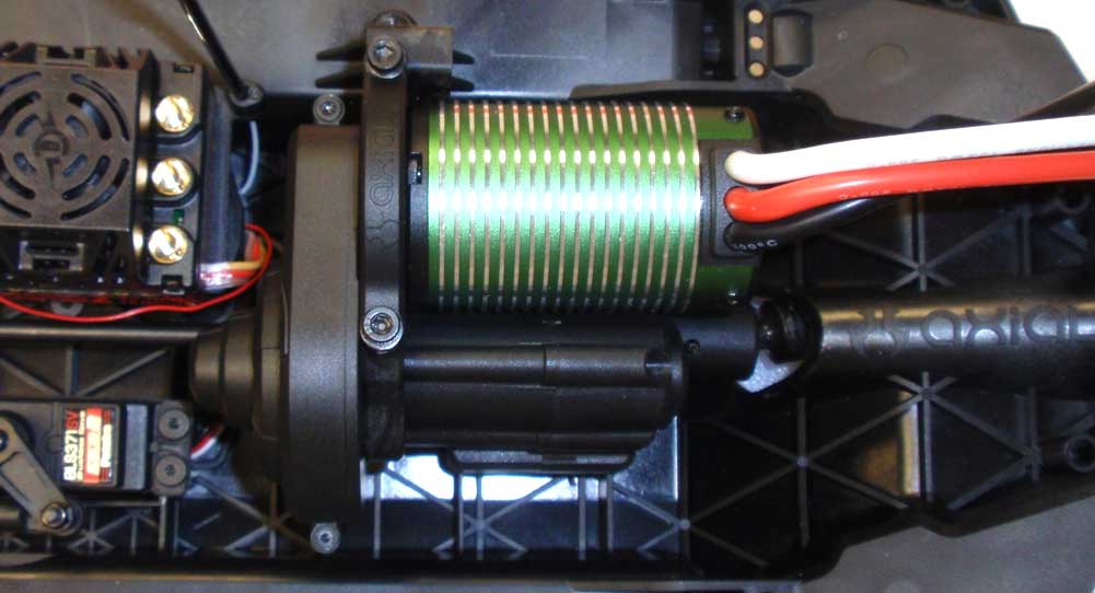
Step 26:
Slide the CVD slider through the opening in the rear of the chassis. Key the front drive axle to the output shaft on the other side of the transmission and lower into place. Attach the transmission to the chassis with the four M3x30 screws. Screw them in a little at a time until all four are tight.
Awesome job. Give the rear CVD a turn to make sure the drivetrain is rotating freely. There will be a little resistance depending on the motor you are using, but overall it should turn smoothly. Next up, the rear suspension.
Axial Yeti XL Online Build – Part 10
The Axial Yeti XL uses a solid rear axle that is connected to the chassis via long, molded links. The rear is caged to support the shocks and an interesting box that could be used to hold something like a light controller or spare parts.
Build Notes:
• Some of the build steps can be a little tricky, so I’ve come up with a certain build order that I feel will make it easy for you. I’ve outlined them in the actual step.
Step 1:
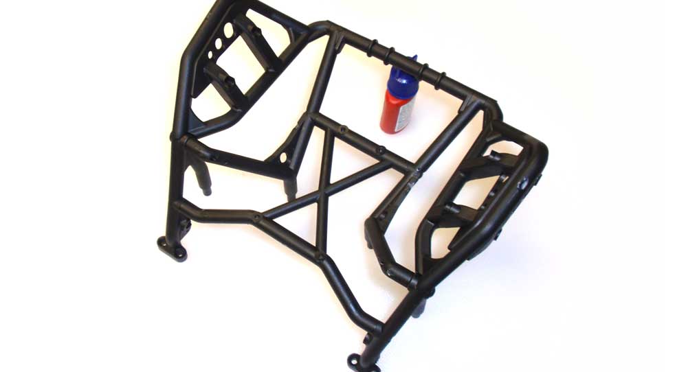
Start this step by assembling hte rear cage. I would suggest arranging the parts prior to assembly to make sure you have them correct. The picture shows the completed rear cage; you can use that for reference.
Step 2:
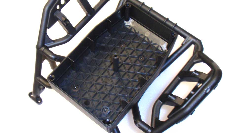
After you’ve completed the cage, attach the box bottom to it.
Step 3:
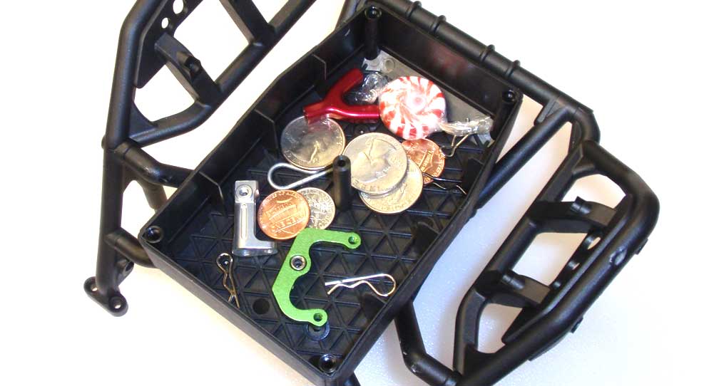
Axial doesn’t supply anything to go in here, so I’m not entirely sure what it’s for; maybe a light controller or something. I used it to put a few spare parts I had lying around. This might make some very interesting noises when the Yeti is running.
Step 4:
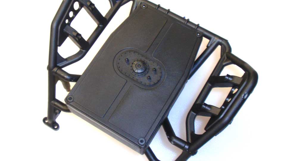
Install the box lid.
Step 5:
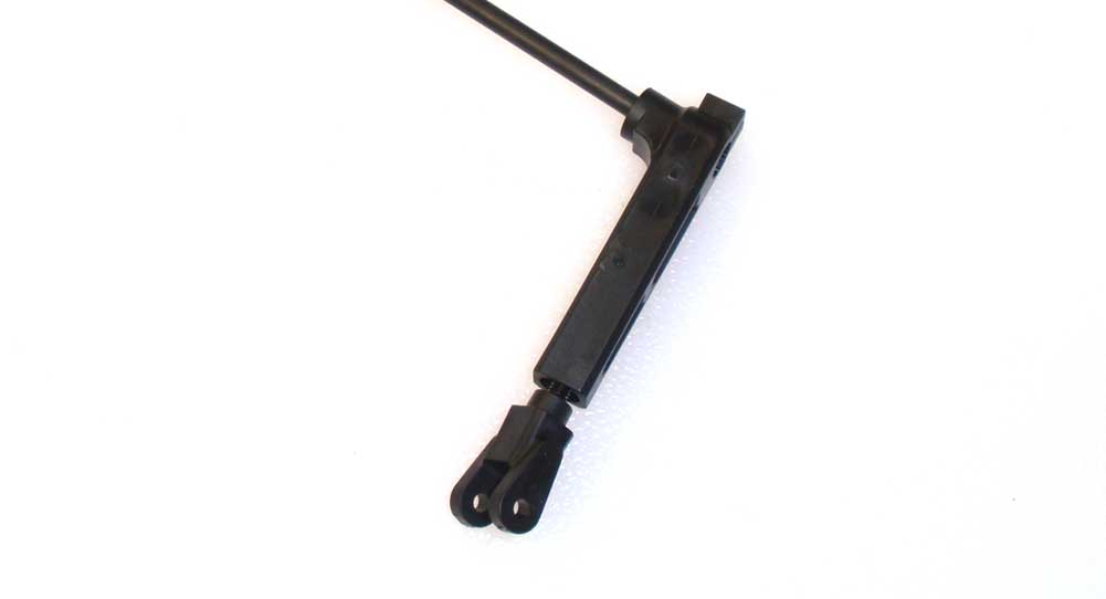
The anti-roll bar is probably one of the most welcomed features of this truck! Start by slipping the bar through the brace and then screwing the U-joint onto the bar. Go ahead and do this to both sides.
Step 6:
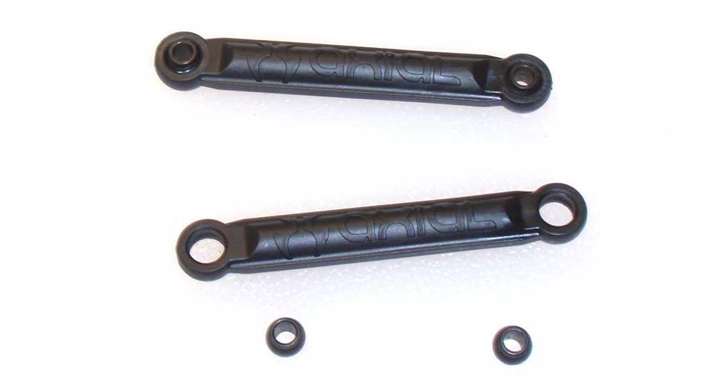
Press the plastic balls into the molded anti-roll bar links.
Step 7:
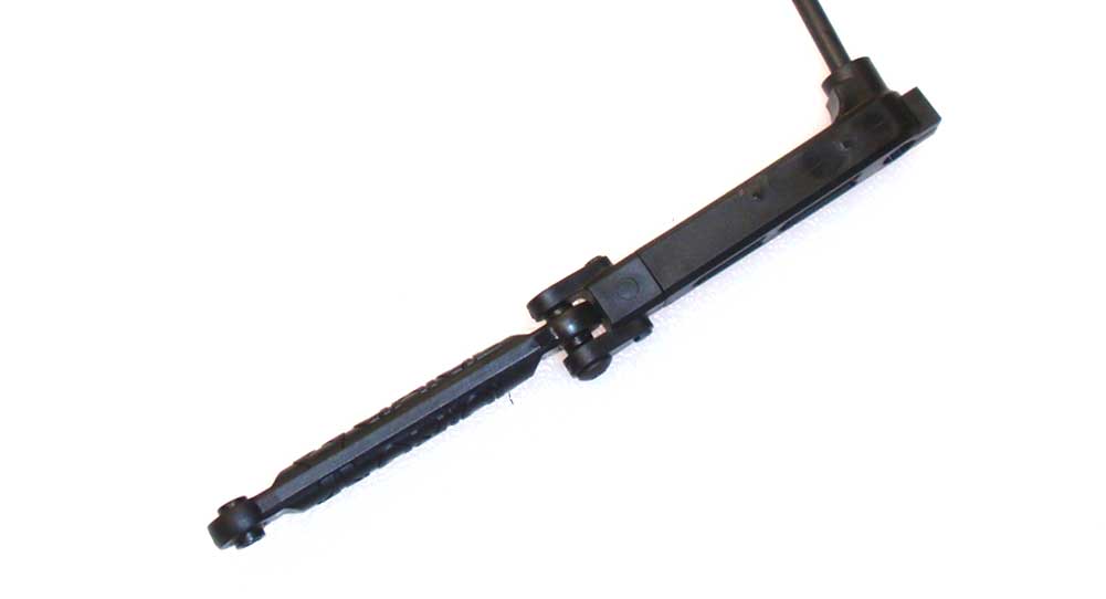
Slip the links into the U-joint and secure with the M3 screw. Do not overtighten; we want free movement of the link.
Step 8:
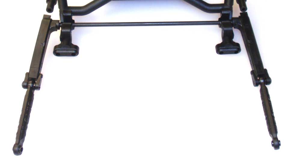
Slide the link up and into place on the back of the cage and use the two AX31005[3] braces to capture it. These braces need to be pressed between the cage an the anti-roll bar. There is a trick to assembling this…
Step 9:
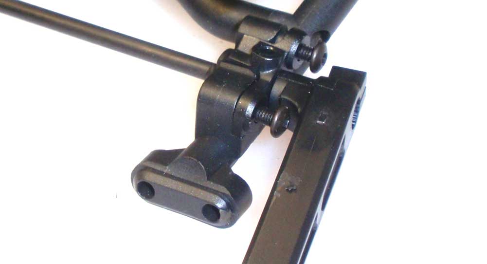
First, press one brace into place and thread the screws in to hold it. Don’t thread them in all the way.
Step 10:
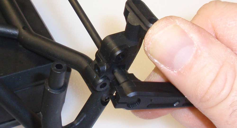
Using your thumb to flex the foot of the cage, pull the anti-roll bar towards you and slip the other brace into place. Insert the M3 screws and tighten both sides down.
Step 11:
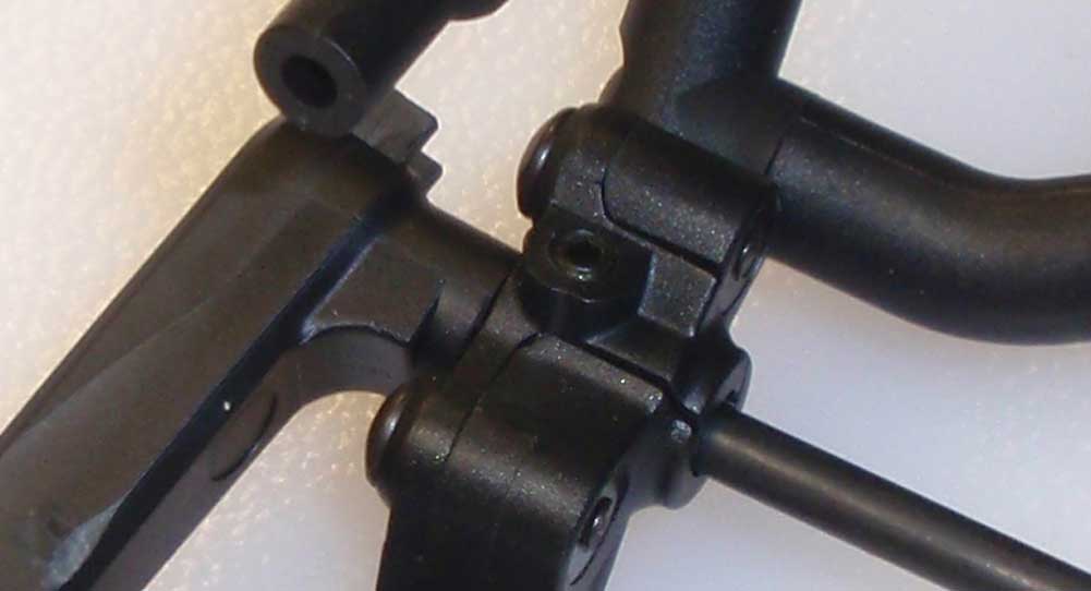
Insert the M3 set screws and tighten down just enough to make contact with the anti-roll bar, then back off a teeny tiny bit. You want these to keep the bar from moving back and forth, but not to hinder it’s rotation.
Step 12:
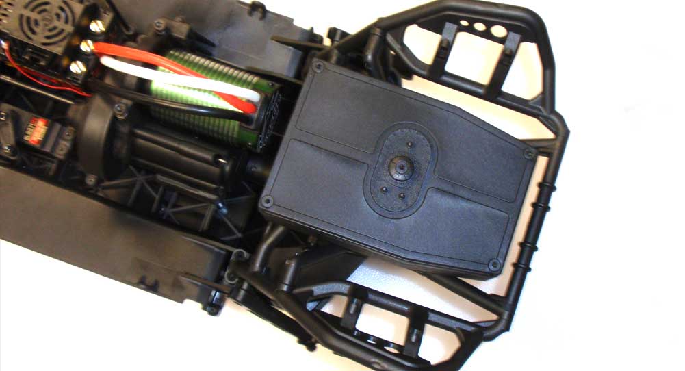
Align the rear cage with the chassis assembly and attach in this order: screw in the four M3x18 screw first (from the bottom) followed by the four M3x18 screws through the top.
Step 13:
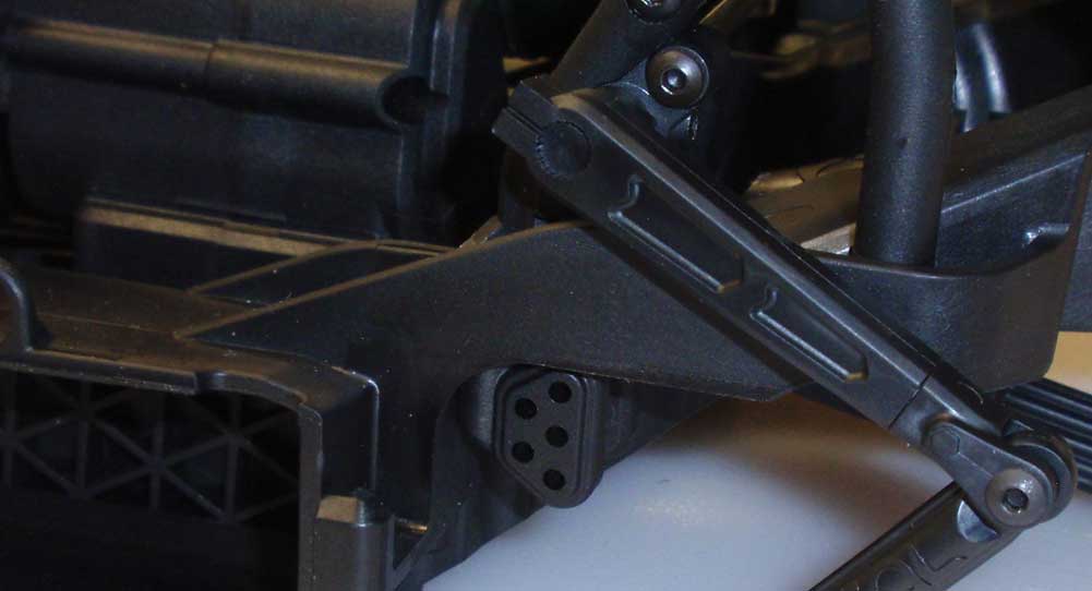
Here’s a look at the link mounts from the above step.
Step 14:
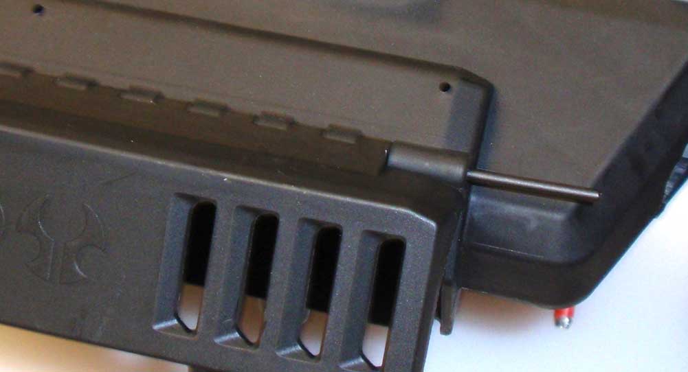
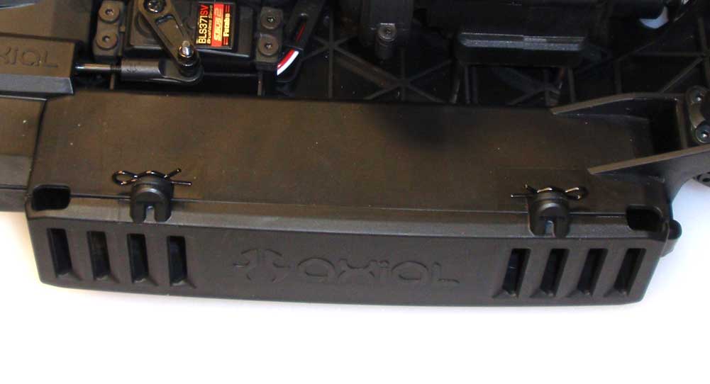
Mate the battery doors to the chassis and slide the two long molded pins into place. Capture the front pin with a M3x6 screw (on both sides).
Step 15:
Flip the doors up and secure with the body clips.
Step 16:
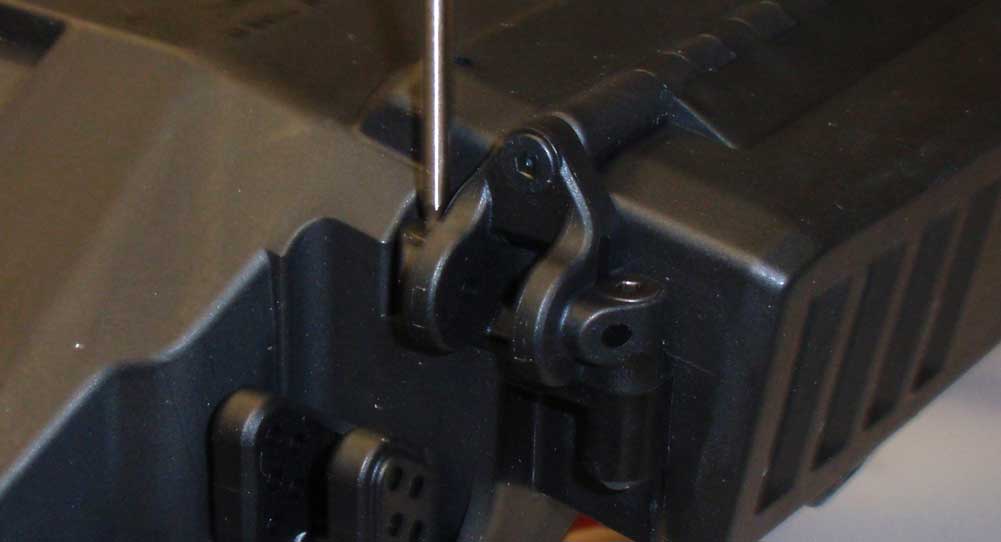
Attach a link brace to each side of the chassis.
Step 17:
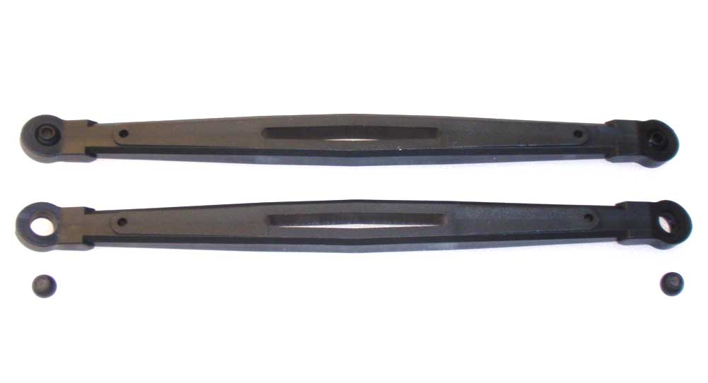
Pop the plastic balls into the ends of the inner links.
Step 18:
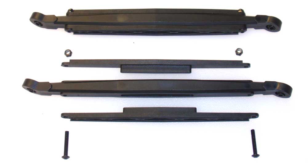
Attach the molded braces to both of the inner links. The molds are a little tight so getting the tab into the slot on the link could prove a bit tricky. You can get it started and then ‘compress’ it with the M3 screw and locknut.
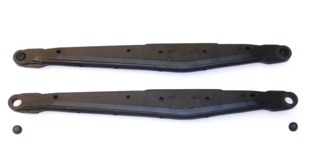
Step 19:
Pop the plastic balls into the ends of the outer links.
Step 20:
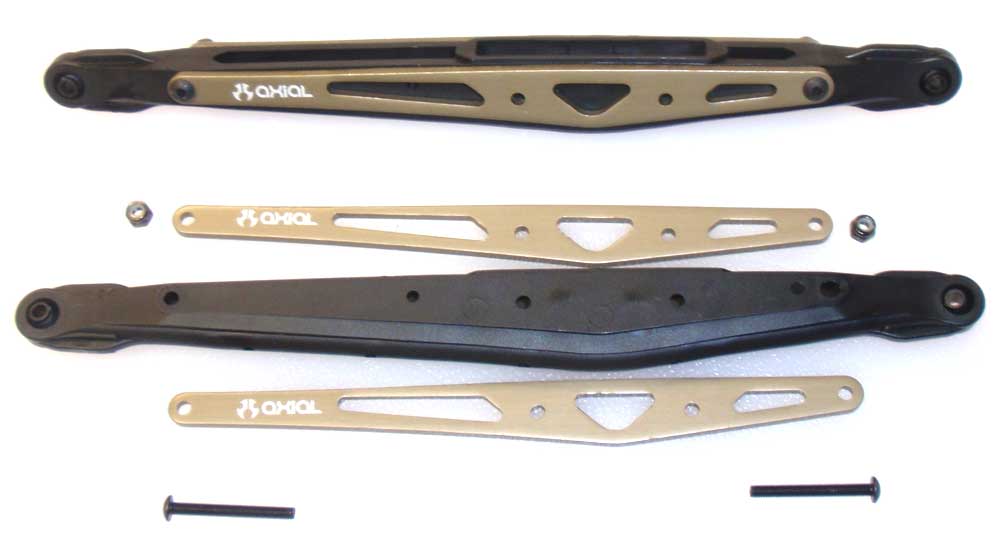
Attach the aluminum braces to both the outer links.
Step 21:
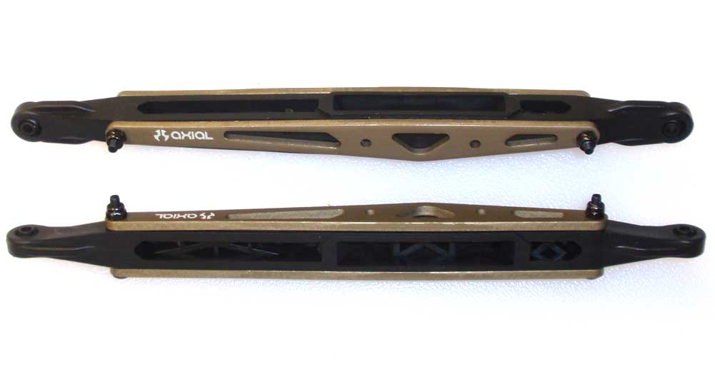
The manual has you building both links the same, but I chose to build one ‘opposite’ so that the screws on both face inwards. This is completely optional.
Step 22:
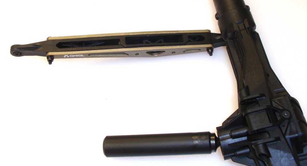
Attach the outer links to the rear axle as shown. Notice the screws on the link facing inward. Also note the orientation of the link. Attach both sides.
Step 23:
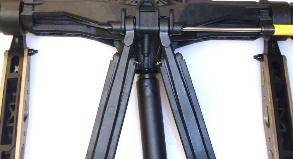
Connect the inner links by sliding them into place on the rear axle and securing with the 45mm screw (and nut). Not the orientation of the rod ends.
Step 24:
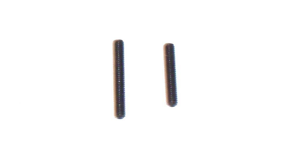
I wanted to point out another slight error in my manual (yours might be fixed). It shows six of the 6mm setscrews being used; I only have four. I did have 2 of the shorter ones though, so I had to figure out the best place to use these.
Step 25:
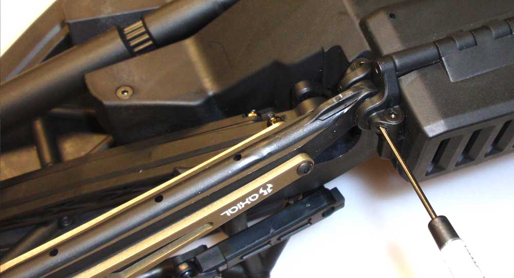
Mate the rear slider shaft together and attach the outer links as shown using the 6mm set screws.
Step 26:
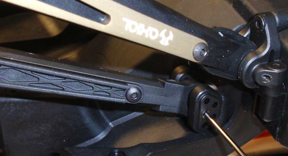
Now attach the inner links in the ‘center’ hole using the 6mm set screws.
Step 27:
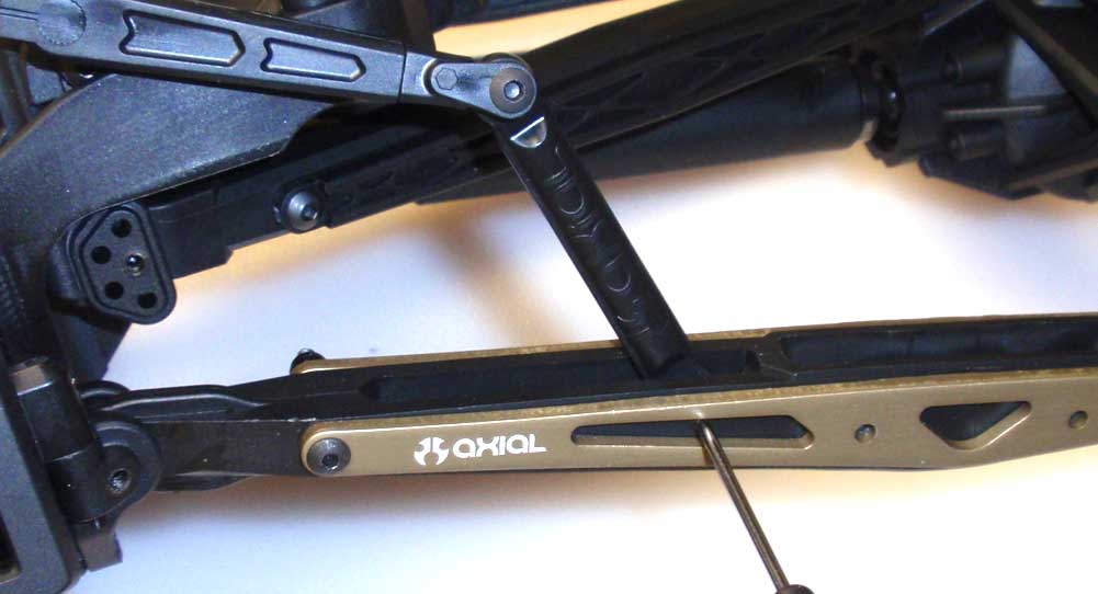
Finally, attach the anti-roll bars to the outer links using the shorter set screws. You want to try and center all set screws from Steps 154, 155 and 156.
Now we have the front and rear drive sections attached to the chassis. Swivel the rear axle a few times to make sure there is no binding. You may feel a little resistance, but that’s just the anti-roll bar doing it’s job.
Axial Yeti XL Online Build – Part 11
Axial has fitted the Yeti XL with a pretty substantial set of shocks. These dampers feature aluminum threaded bodies, dual springs and some cool-looking (however fake) reservoirs.
Build Notes:
• Shocks can always be messy, so I would suggest some cleaning rags and some sort of shock stand for building.
• Whenever I build shocks, I like to highlight the pistons to make them easier to read. White pistons get a black Sharpie mark, black pistons get a silver Sharpie mark.
Step 1:
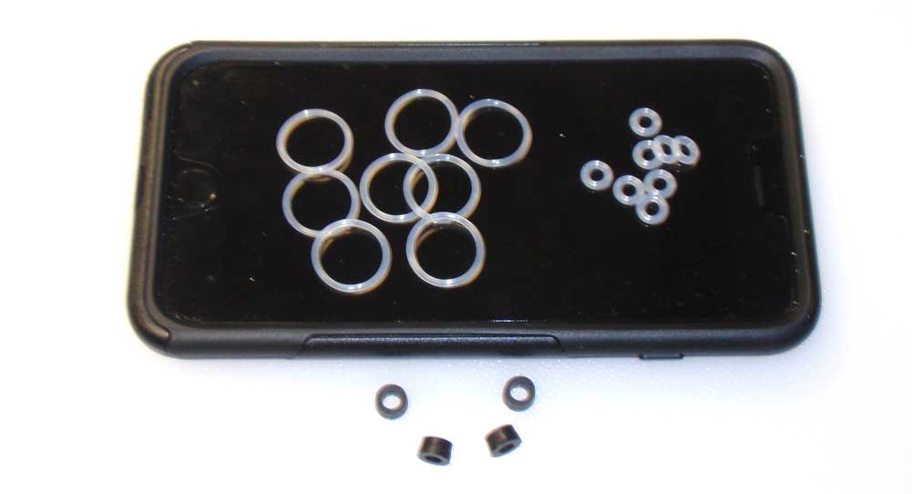
Before we start building, I’ve laid out all the o-rings we’ll be using so you can get aquainted with them. The large clear o-rings are for the cap and lower cartridge, the small clear o-rings go inside the lower cartridge and the black tapered rings act as limiters on the outside of the shock shafts.
Step 2:
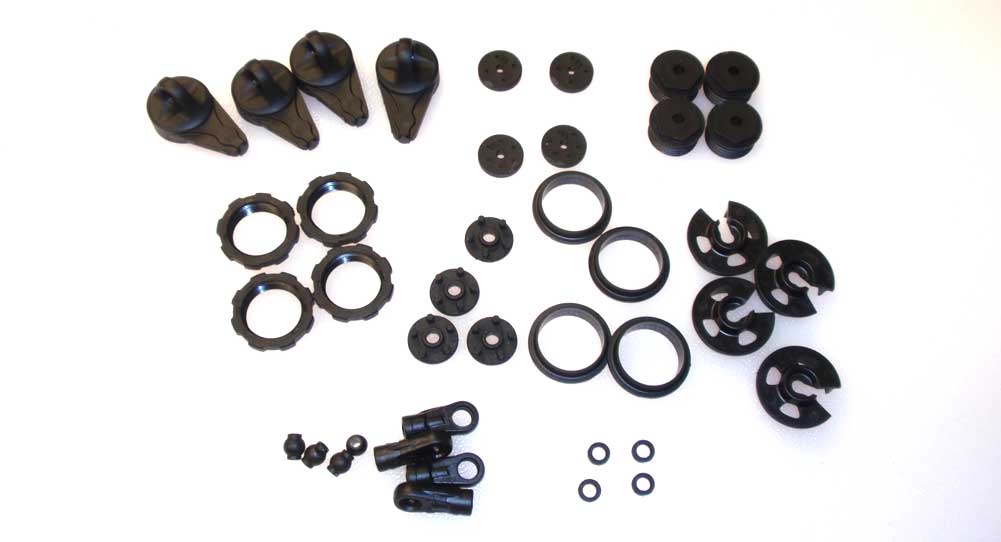
I’ve also separated all the plastic we’ll be using during this step as well. This keeps me organized and makes the parts readily available when needed.
Step 3:
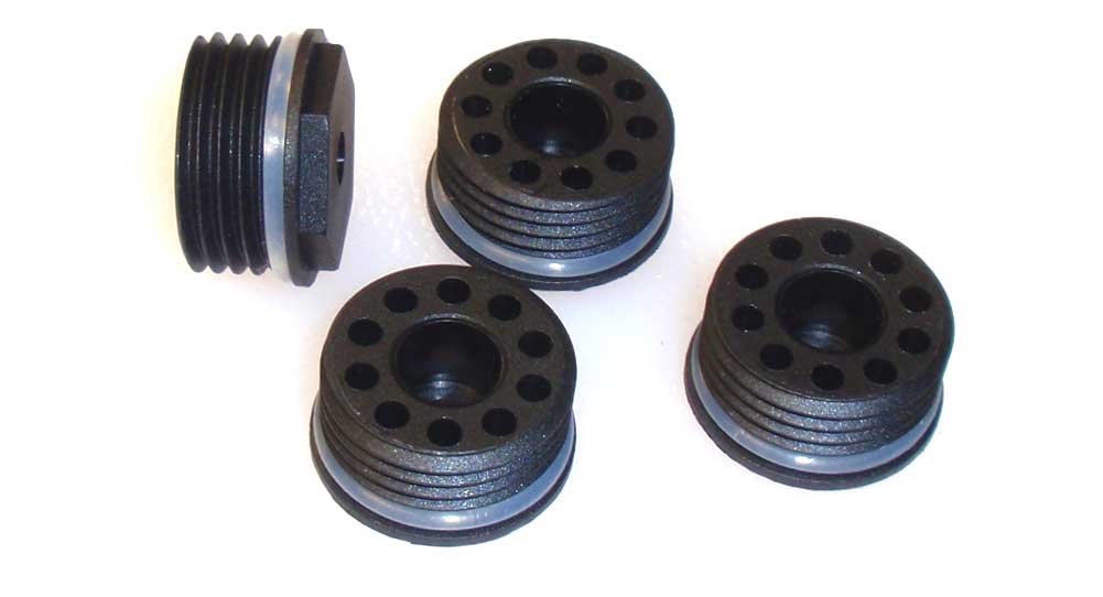
The first step is to slide a large clear o-ring over the four lower cartridges.
Step 4:
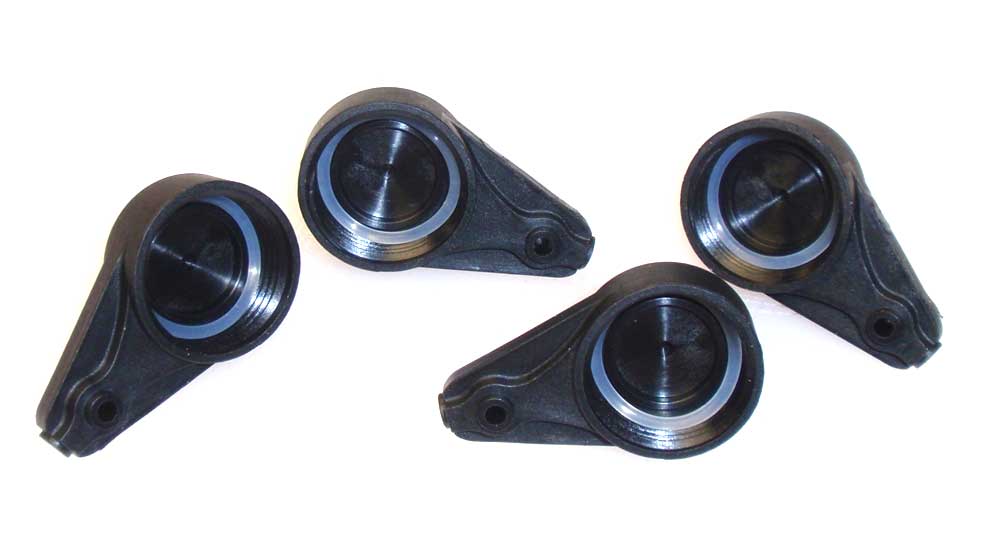
Install the other four large clear o-rings into the shock caps. Carefully press them up and into the cap.
Step 5:
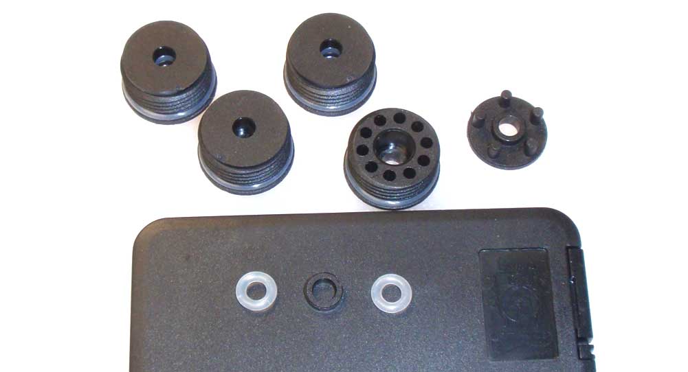
Build four cartridges. Install a small clear o-ring, a plastic spacer and another clear o-ring. Press firmly to seat and then install the cartridge cap. These caps are a press fit, however they didn’t seem very snug. I’ll be curious as to how well they stay together after a few hard romp sessions out in the dirt.
Step 6:
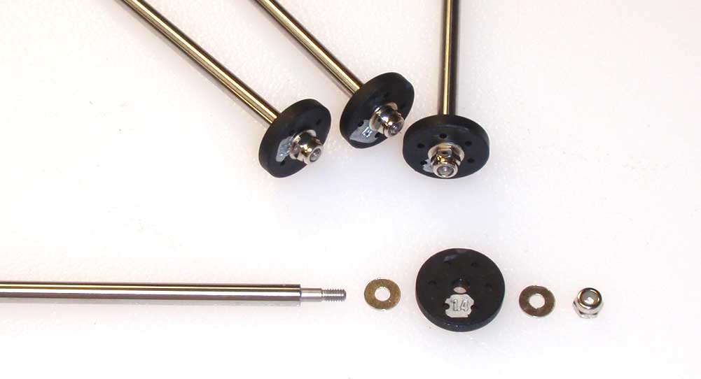
The front and rear shock shafts are the same length but will require different pistons. To make the pistons easier to identify, I marked them with a silver Sharpie so they’d be easier to read. The front shafts get a 1.4, 4-hole piston; the rear shafts get the 1.4, 6-hole pistons. Assemble by installing a .5mm washer, the appropriate piston, another .5mm shim and the locknut.
Step 7:

Carefully thread the cartridges into the lower part of the shock body. Tighten with the included tool. Be careful not to pinch the o-ring.
Step 8:
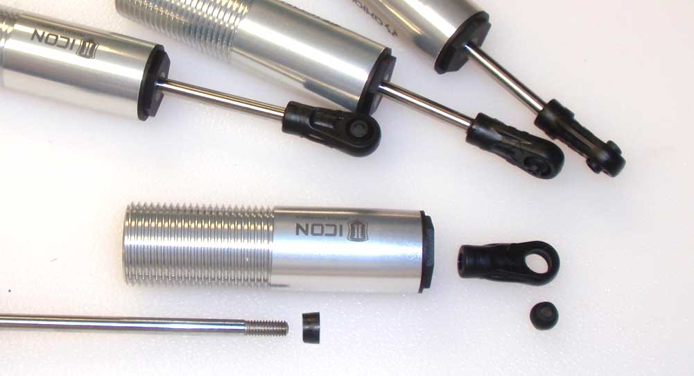
Apply a small drop of fluid on the threads of the shaft and carefully push it through the shock body (and cartridge). Slide one of the tapered o-rings onto the shaft followed by a plastic rod end. Finally, pop a plastic ball into each rod end.
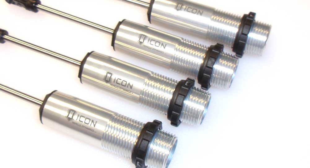
Step 9:
Thread a shock collar onto each shock.
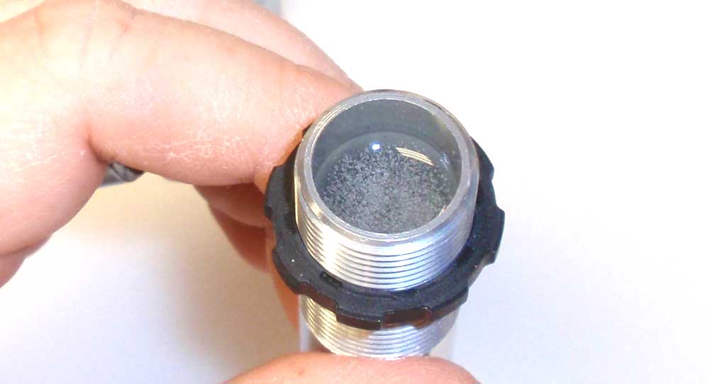
Step 10:
Fill each shock with oil; the fronts should get 30wt, the rears 10wt. Slowly plunge the shock shaft up and down a few times to release any air from under the piston. You should see quite a few bubbles like that in the picture.
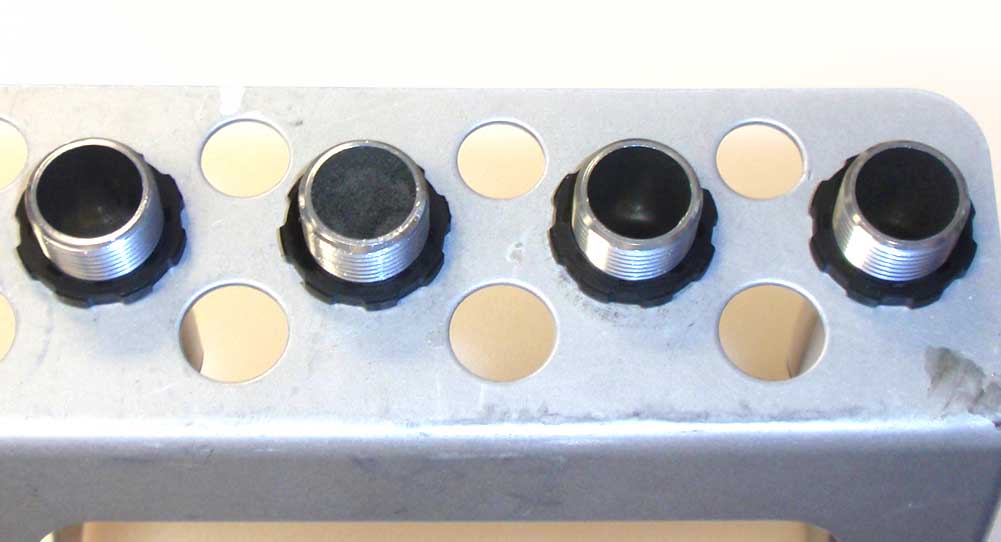
Step 11:
Fill the shock back up to the top and set in a shock stand to let the air bubbles rise to the top.
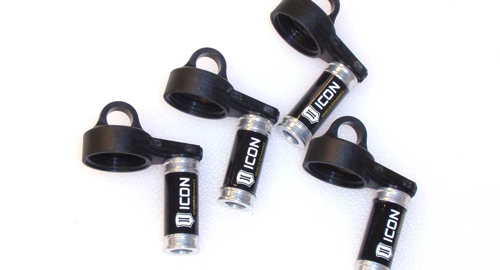
Step 12:
While we’re waiting for that air bubbles, we’ll assemble the shock caps. Wrap each aluminum reservoir with an Icon sticker and attach it to the caps.
Step 13:
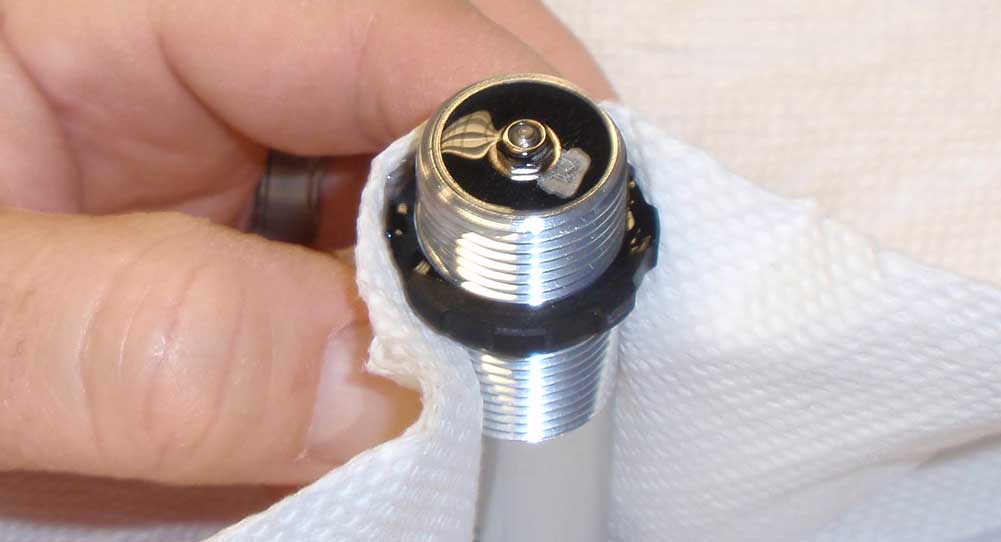
Now for the messy part. Grab a shock and wrap it with a paper towel. Set the shock on your work surface and slowly compress it all the way. It should end up looking like the picture above.
Step 14:
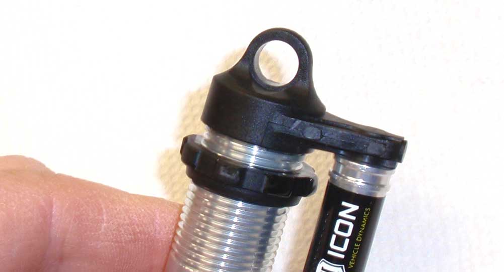
Attach the cap. Be careful because I found these caps easy to cross thread. Tighten slowly to make sure you don’t do that.
Step 15:
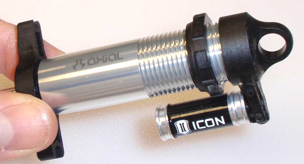
Take your cartridge tool and, with it installed, tighten the cap down nice and tight. Clean any excess oil off the shock.
Step 16:
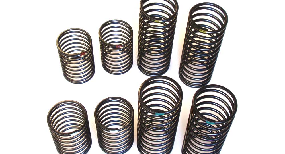
Axial has included four different shock springs; white (short, 7.9lbs), red (short, 3.2lb), yellow (long, 7.9lb) and green (long, 6.3lb). These are denoted by a little paint applied near the top of the coils.
Step 17:
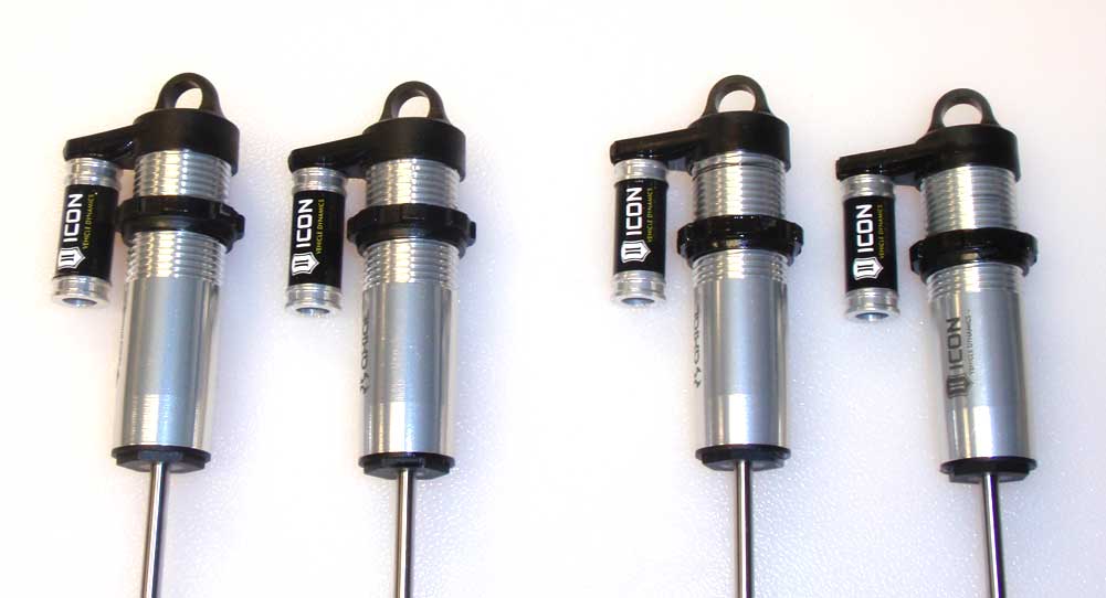
Before we install the springs, set the pre-load per the manual; front, 10mm; rear, 14mm. I actually found that the front pre-loads needed to be more around 15mm but you can adjust that after the Yeti is completely built. Also, unless you marked them, this is the only way to tell which are the front and which are the rear. Make sure you keep the separate.
Step 18:
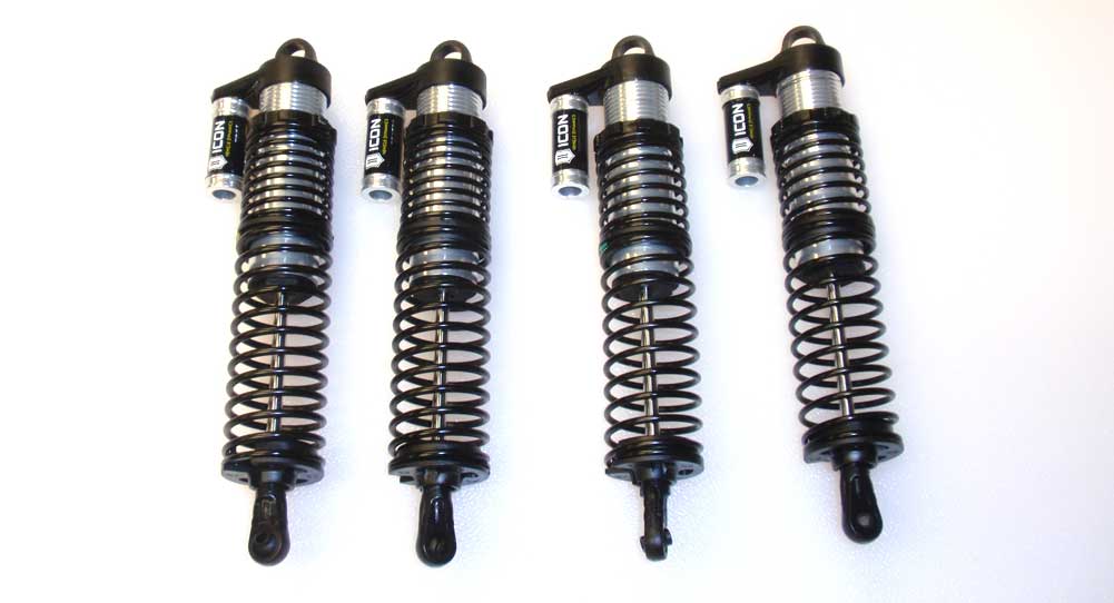
Spring install; on the front, slide the short white spring followed by the spring coupler, then the long yellow spring followed by the lower spring retainer. On the rear, slide the short red spring followed by the spring coupler, then the long green spring followed by the lower spring retainer.
Step 19:
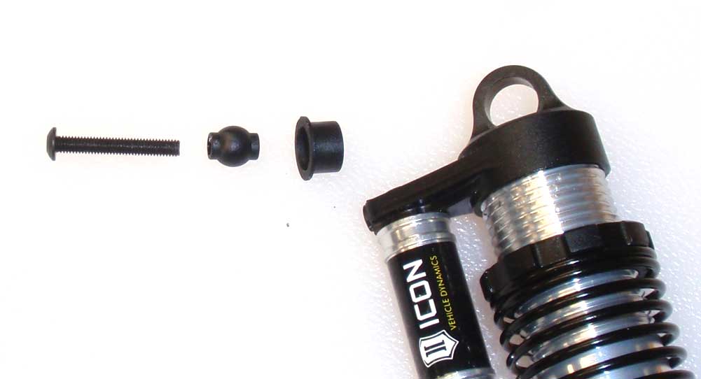
Feed the 20mm screw through the plastic ball, the plastic retainer and then the shock cap. The shock shown here is for the front right side of the Yeti.
Step 20:
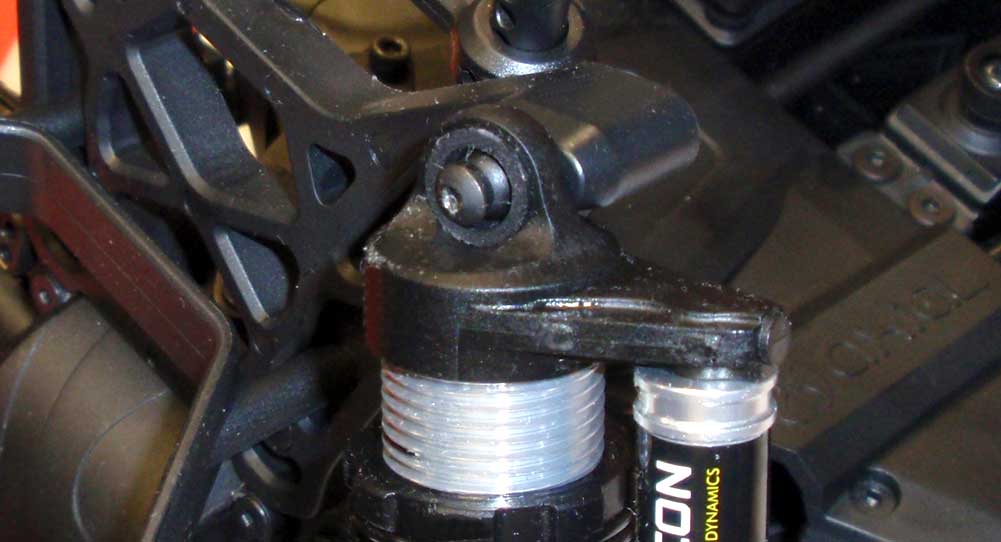
Screw the assembly into the middle hole on the shock tower. Yes, you’re now looking at the front left side of the Yeti. Just make sure the faux reservoirs face out.
Step 21:
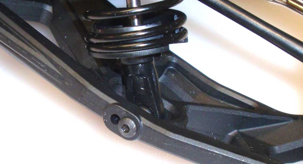
Slip the rod end of the front shocks into the front arms and attach using the outside hole.
Step 22:
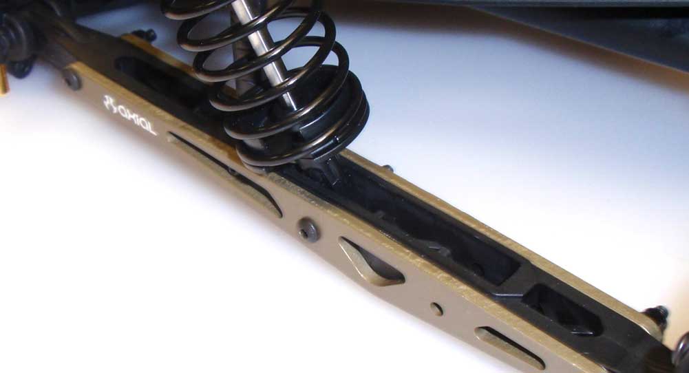
Attach the rear shocks into the hole on the outer link using a 25mm screw and locknut.
Step 23:
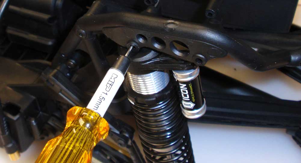
Press the plastic ball into the retainer and insert it into the BACK side of the shock cap. Now slip that assembly up into the shock mount. It was a little tricky keeping all this together so I used a wrench to ‘locate’ the hole all the way through.
Step 24:
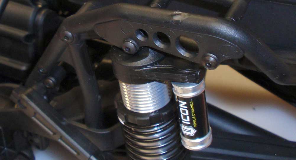
Remove the wrench and feed the 25mm screw through the assembly and into the cross brace. Finish attaching the cross brace.
Yes, this was probably the most time-consuming step in the build but you know what, you’re almost done! All that’s left is cage, body, wheels and tires!
Axial Yeti XL Online Build – Part 12
The final step in the Axial Yeti XL build is the assembly of the cage, the body panels and the wheels and tires. Because I wanted something spectacular with the body, I had my white/red/black paint job squirted on it by Larry Genova over at http://www.kustomrcgraphics.com.
Build Notes:
• While building the cage, I came across an issue with the screws assembling the back half. The rear screws, the ones that secure the tire holder to the left and right cage halves, call out AXA37 (25mm) on the upper and lower attachment points. They were too long to fit in the location stated. However, the side bar in the manual shows a picture of the short screws (AXA437) as being 25mm and the longer ones (AXA439) as being 20mm. It’s off, so just keep this in mind when assembling the cage.
[divider]
Step 1:
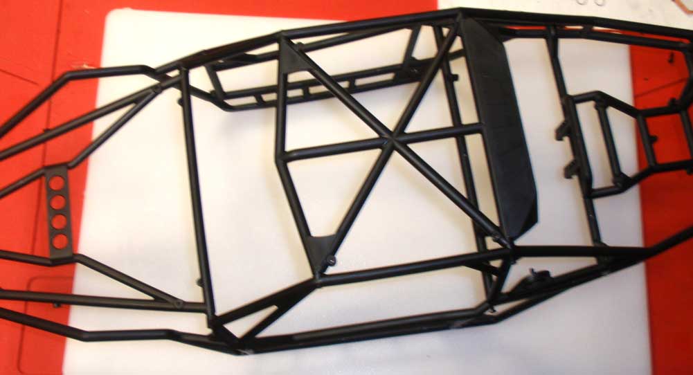
I’ve assembled the cage per the pictures in the manual. Again, you’ll have to figure out the screws while you’re building it. Then again, your manual may be correct.
Step 2:
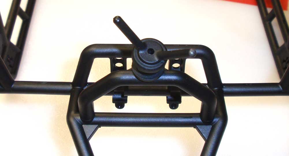
The manual has you installing the tire carrier at a later time, but I did it now while it was off the truck to make it easier.
Step 3:
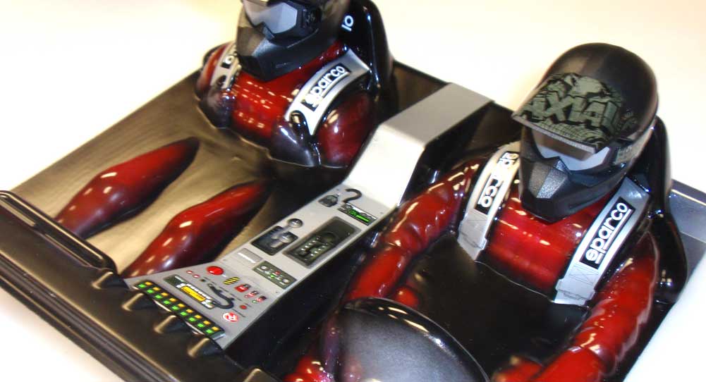
After getting the body and drivers back from http://www.kustomrcgraphics.com, I attached the helmets and stickers everything up.
Step 4:
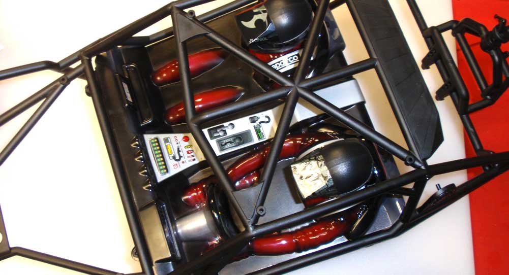
have to rotate the rear attachment point to complete the assembly.
Step 5:
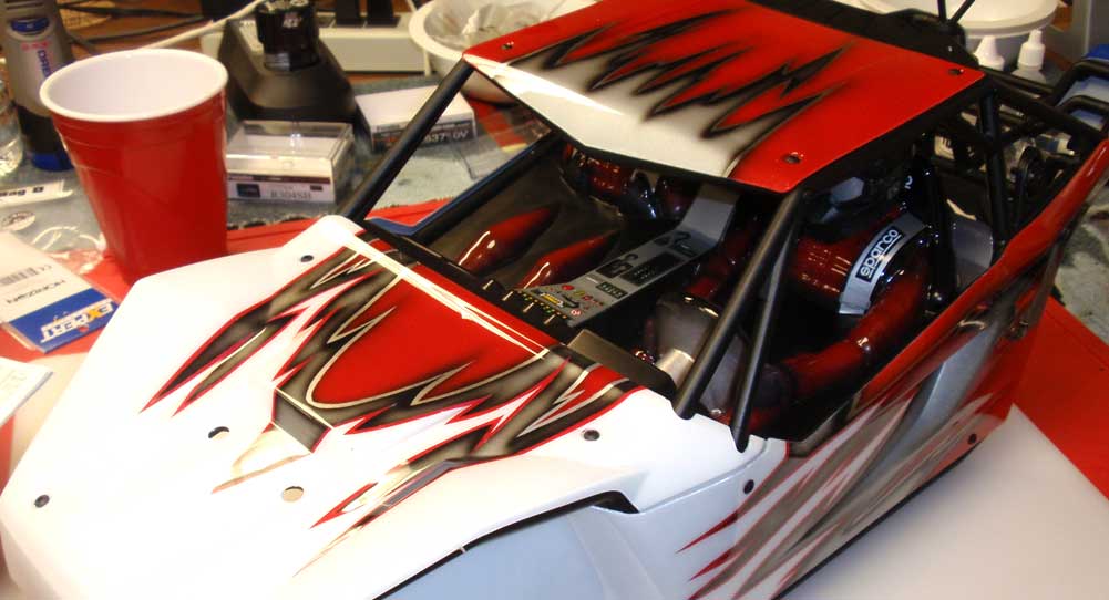
I removed the painted body panels from the packaging and installed. Start with the roof, then the hood, then the side panels. I think it looks amazing!
Step 6:
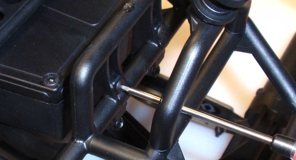
Fit the completed cage to the back of the chassis and secure with the screw-in clips.
Step 7:
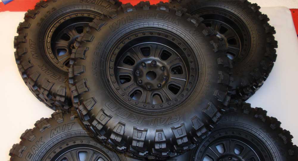
Slide the wheels into the tires, making sure the bead properly seated in the wheel. Glue the tires and wheels together using your favorite method. My favorite method is to us the CompetitionX Gloo Toobs.
Step 8:
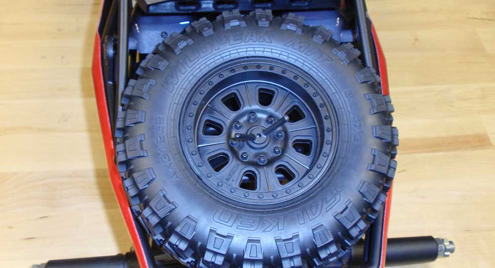
Remove the twist on tire holder, attach the tire and re-install the holder.
Step 9:
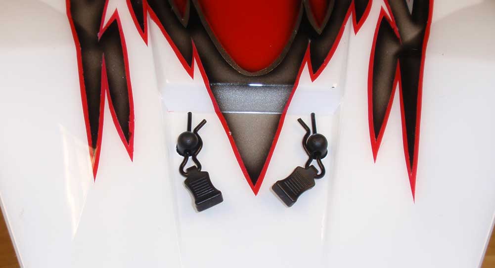
Slide the body clips through the plastic tabs and secure the front of the body to the chassis.
Step 10:
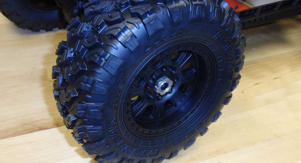
Fit the tires to the hubs and secure with the aluminum hex nuts.
Congratulations on your completed Axial Yeti XL! Take a step back and enjoy the look of this rig; it’s an awesome sight! Charge your packs and get this beast out where it belongs!

