

Team Associated B44.3 Online Build
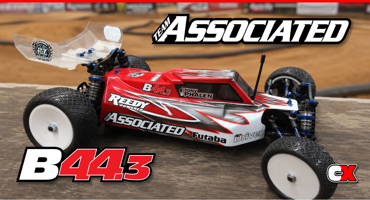
The Factory Team B44.3 is the third generation 4WD buggy from Team Associated. This platform has already generated a whopping 3 IFMAR World Championships and 4 ROAR National titles, not to mention a slew of other Regional wins. The A-Team has taken the best parts of the previous cars and, along with some new features, stuffed it all into a tight little package.
One of the coolest features is the ability to build this buggy in either a Front Motor configuration (FT) or a Rear Motor configuration (RM). Both of these have advantages depending on track conditions and can be built with parts supplied in the kit.
We got our hands on one and will be supplying one of CompetitionX‘s famous step-by-step builds.
Team Associated B44.3 Online Build – Part 1
The B44.3 uses 3 gear differentials; one in the front, one in the center and one in the rear. All 3 of these are fluid-filled and can be tuned to make the B44.3 handle however you want on almost any surface.
While they are pretty easy to build, there were a few instances where I had to deviate from the manual to make things fit. So, without further ado, here we go…
Build Notes:
• First off, we’ll be working with black grease and differential fluid. Yes, you will spill some and yes, you will get some on your fingers. It’s a good idea to have some rags handy for clean up (Wet Wipes might be good as well).
• The instructions call for four #9888 shims on the outdrives; 2 outside the diff and 2 inside. If you do use four, you’ll never get the roll pin through the outdrive. You can use three shims, but make sure you use ONE outside and TWO inside. This will keep the internal sun gear spaced correctly and allow the diff to function properly. The manual actually says you can adjust shims for the best fit, but do you really want to build the entire diff only to find out it’s wrong? This worked for me.
Step 1
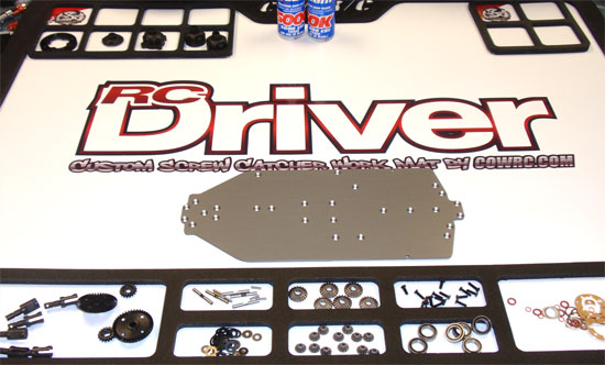
The first thing we want to do is make sure that you have a nice, clean space to work on. I’ll be using one of CowRC’s cool magnetic pit mats. This mat is huge and has foam-lined compartments, allowing me to put separate all the parts for a specific build step. The best part is, of course, the magentic backing so I won’t be dropping any more screws on the ground. I do that alot.
Step 2
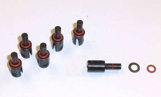
Before we start building, I’m going to prep all the outdrives. Slide the small red o-ring over the outdrive and seat it in the first groove. It should just drop into place. Next, slide one shim (yes, one, even though the manual states two) all the way over the outdrive followed by one larger red o-ring. Go ahead and prep all six outdrives.
Step 3
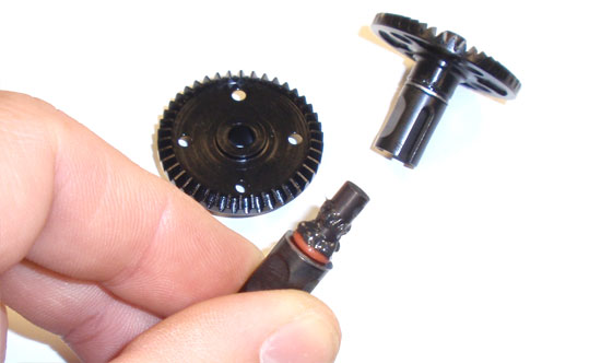
Apply some black grease to the both o-rings as shown and slowly slide the outdrive assembly into the metal differential gear. Don’t be afraid to use too much grease; it only helps coat the o-rings and seal the diff. Wipe away any spare grease once assembled. Build two of these.
Step 4
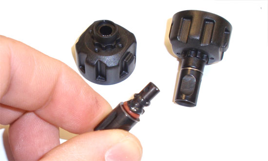
Follow the same procedure as you did in Step 3 but this time insert it into the diff housing. Build 2 of these.
Step 5
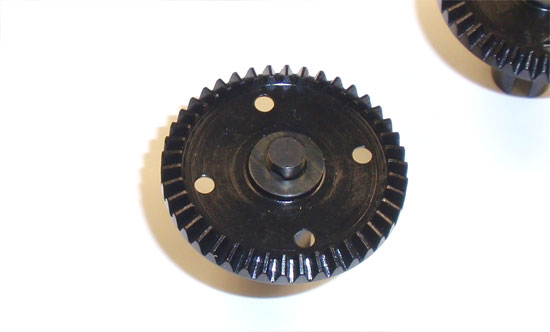
Stand the outdrive side up that has the metal gear and slide 2 of the #9888 shims onto the outdrive. Do this on both assemblies.
Step 6
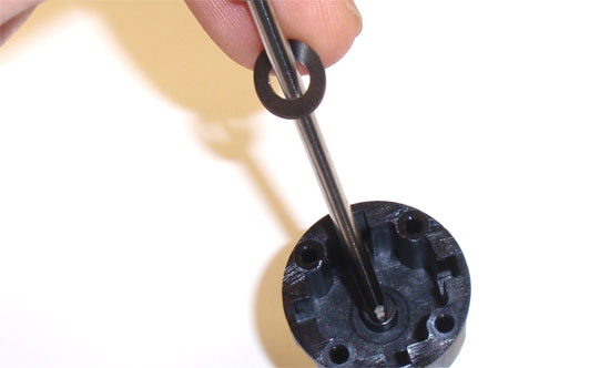
We’re going to add two of the #9888 shims onto the diff housing side as well. To make things a little easier, I usually slide any shims on a hex wrench and then place the tip on the outdrive. When I release the shims, the fall right into place.
Step 7
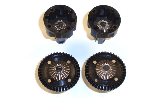
Slide the 2x9mm roll pin into the hole in the outdrive and key a sun gear to the pin. I usually use a dab of black grease to keep the gear in place. Do this on all four diff assemblies.
Step 8
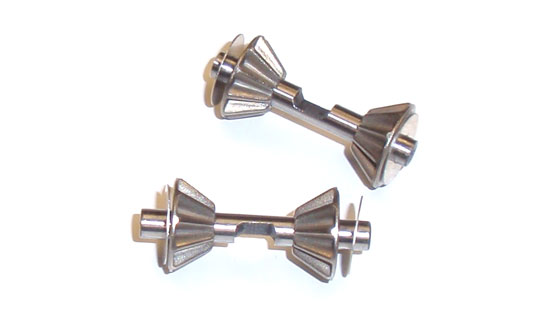
Build four of these smaller sun gear assemblies; each shaft should have two sun gears (facing each other) and two small shims.
Step 9
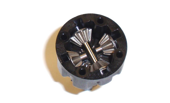
Key one sun gear assembly to the diff housing as shown, making sure the notch in the shaft is facing up. Then do the same thing with then second sun gear assembly, making sure the notch in the shaft is facing down. As you can see, the notches line up and key together. Build two of these.
Step 10
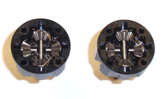
Take the 5000wt diff fluid and pour it into the diff housing. Let it set for a few seconds so the fluid can sink into all the nooks and crannies, then add a little more. You want to put just enough to cover the sun gears; don’t go over this or you’ll have a mess during the rest of the assembly.
Step 11
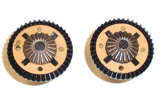
Set the diff gasket in place, lining up the round holes in the gasket to the mounting holes in the assembly. You can use a very small dab of black grease to keep it the gasket in place.
Step 12
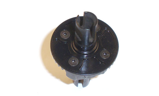
Now take the gasket-side diff assembly and slowly mate it to the diff housing side. Make sure you line up the mounting holes on both assemblies. Press together and, while holding the to halves tightly together, rotate an outdrive to make sure the gears have seated correctly. Now assemble with the four 2.5x10mm screws. Retest your diff to make sure all is rotating smoothly. Assemble both diffs.
Step 13
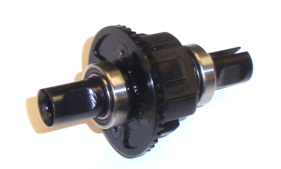
The final step in the front and rear diffs is to add three shims and a 3/8″ bearing to both sides of the diff. The shim count might vary on your car but we won’t know this until we put the diff assembly in the diff housing.
Step 14
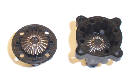
The center diff is much like the front/rear ones. Apply grease to the o-rings on the outdrive and insert into the housing. Add TWO more #9888 shims followed by the large sun gear.
Step 15
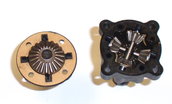
Build your smaller sun gear assemblies and, following the same procedure as we used in Step 9, insert the sun gear assemblies into the diff housing. Attach the diff gasket and fill with fluid.
Step 16
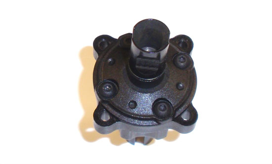
Screw the two halves together using the same procedure as in Step 12.
Step 17
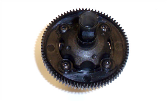
Flip the center diff assembly over and attach the spur gear to it.
Simple as that, we have all three differentials completed! Set them aside and let’s get rocking on the next part of the build.
Team Associated B44.3 Online Build – Part 2
Part 2 of the Team Associated B44.3 build has us assembling the front and rear gearboxes; installing the diffs and building the center CVAs.
Build Notes:
• You’ll want to pay close attention to the build steps as there are 3 different length CVA bones and 3 different axle designs. I’ve specified which go where a little better than the manual; it’s the pictures aren’t 100% descriptive.
• When building the CVAs, AE has included a CVA pin retainer that keeps the pin in place from falling out. Make sure, when you’re installing it, that the ‘gap’ in the retainer is NOT where the pin is located. Rotate the retainer until the ‘gap’ is roughly 90° from the pin. As an added security measure, you can install the set screws provided.
• Be ready for some frustration when installing the sun gear on the center CVAs. Once you get the gear on, you need to force the e-clip into the groove on the shaft. It’s a major pain and I destroyed (or lost) about 7 e-clips trying to complete this step. I would HIGHLY suggest finding a few extra e-clips before starting this step.
Step 1
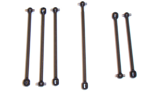
The first thing we need to do is separate the CVAs so you know which ones go where. The three on the left; two are the front axles, the third is the front-center CVA. The long one in the middle is for the rear-center CVA build and the two shortest ones are for the rear axles.
Step 2
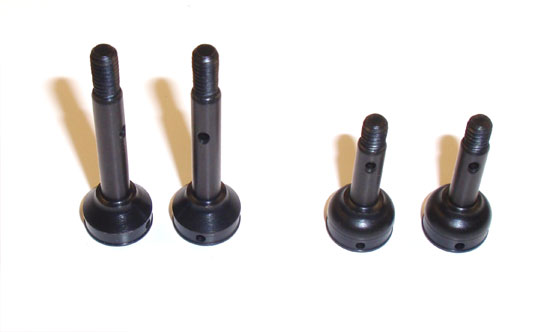
You’ll also want to be familiar with the threaded axles. The longer ones on the left are for the rear, the shorter ones on the right are for the front.
Step 3
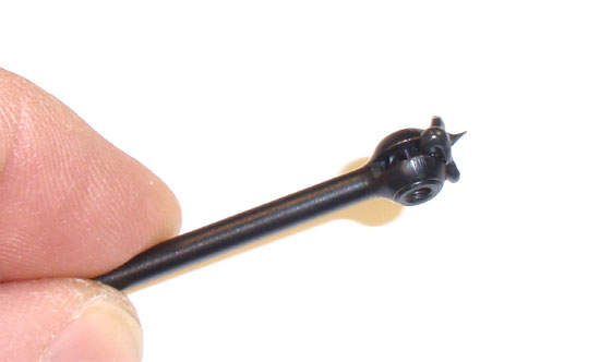
Start by sliding the CVA barrel into place and adding some black grease for lubrication.
Step 4
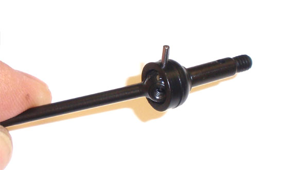
Slide a front axle over the ball and slide the pin through. It should feed through the axle and hole in the CVA barrel.
Step 5
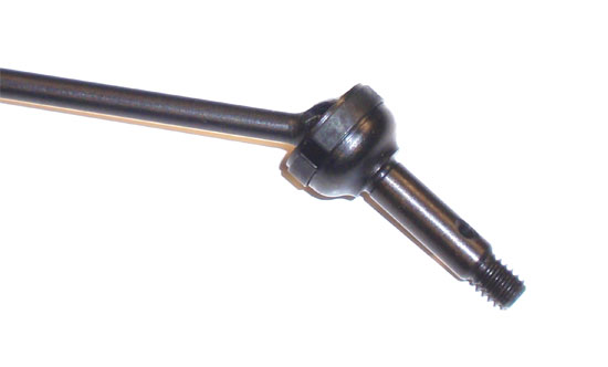
Once the pin is flush in the assembly, slide the CVA pin retainer ring over as shown. Again, make sure the ‘gap’ isn’t sitting where the pin is. You can also insert the setscrew at this point. Build two front and two rears; remember to match up the bones and axles as we mentioned in the Build Notes.
Step 6
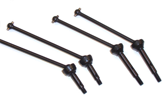
Here is how your completed front/rear CVAs should look.
Step 7
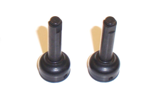
The final two axles look quite different; in fact, the ends don’t have threads. These are the axles for the center CVAs. Both are the same so we don’t need to worry about a front or back one.
Step 8
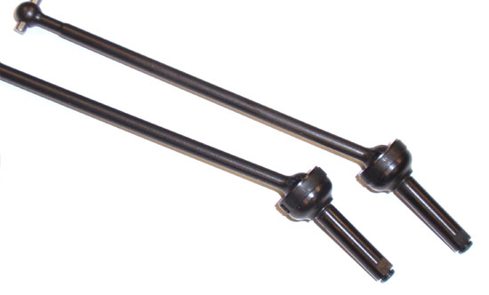
Using the same method as above, build the two center CVAs. Note that one will be longer overall than the other; the longer one goes to the rear.
Step 9
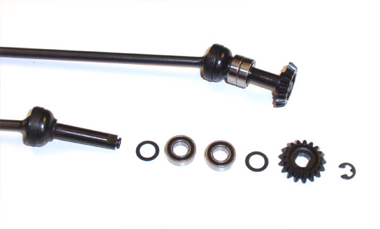
Build the center CVA as follows: Shim, bearing, bearing, shim, sun gear. Once you get that part done, you’ll want to fit the e-clip into the groove on the shaft.
Step 10
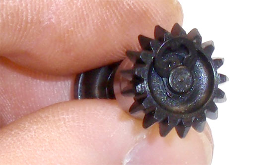
Here’s a close-up of the fun times you’re about to have. As I said before, this is not easy and will result in a little frustration but stick with it … you’ll get it in there. The good news is you get to build two of these.
Step 11
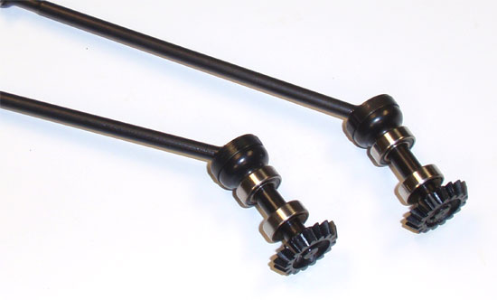
Here is what your completed center CVA assemblies should look like.
Step 12
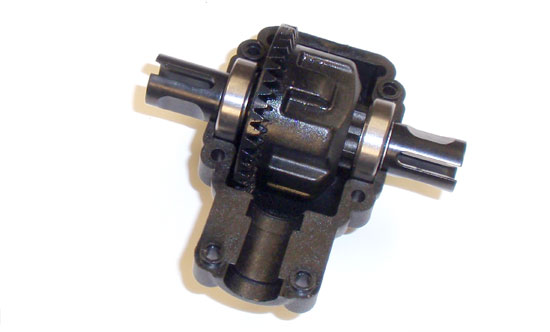
We are now going to assemble the gearboxes. There are two ways to do this; one if you are building the B44.3 in saddle-pack configuration and another if you are building it in the shorty-pack configuration. I will be using the shorty pack config so that’s how the steps will be. First, drop the gear diff into the lower gearbox half.
Step 13
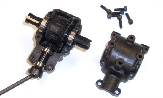
Apply a small drop of black grease to the center CVA sun gear and set it into place on the lower gearbox half. Drop the top gearbox half into position and screw together. Spin the CVA to make sure the assembly spins smoothly and without any binding. If there is binding, open the gearbox back up, pull the diff out and remove one shim off the differential. You’ll want to experiment with which side; removing a shim from the gear side will also open the gear mesh between the diff gear and the input shaft gear. Removing a shim from the opposite side will keep the gear mesh tighter.
Step 14
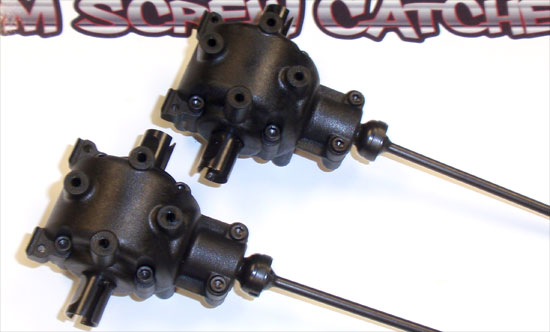
A final look at our gearbox assemblies. Set these aside. Good job.
Team Associated B44.3 Online Build – Part 3
The Team Associated B44.3 uses a ball bearing supported, dual bellcrank system for the steering. This is a simple step and should only take you a few minutes to do.
Build Notes:
• None.
Step 1
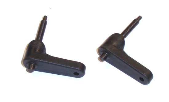
To start, slide the two steering posts up through the bellcrank arms. Make sure the hexed end on the posts mates up with the hexed slot in the arms.
Step 2
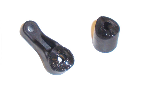
While this is not in the manual, it’s a trick I learned quite a few years ago to help keep the servo saver from sticking or pre-maturely wearing. Apply a light coat of black grease onto the areas shown prior to assembly.
Step 3

Before assembly, we need to prep the servo saver spring by compressing it a few times.
Step 4
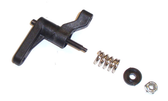
Now put it all together; lower servo arm, spring, spring retainer and locknut. The manual states a 1mm gap but I found that, at 1mm, the plastic spring retainer starts to distort. Just get it as close to 1mm as you can without to much distortion. Now build the other servo bellcrank arm.
Step 5
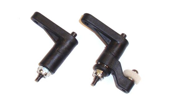
Here’s a look at your pair of assembled servo arms. You’ll notice I also attached the ballstud and foamy thing.
Step 6
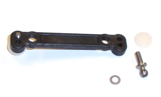
Attach the pair of ball studs to the steering rack. Don’t forget the aluminum spacer and foamy thing.
Step 7
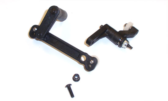
Attach the two steering arms to the steering rack. The hat washer inserts from the top, the screw from the bottom. Note the orientation of the rack and the steering arms.
Step 8
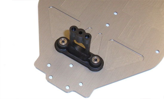
Press the two small-hole bearings into the steering retainer column and attach this assembly to the chassis.
Step 9
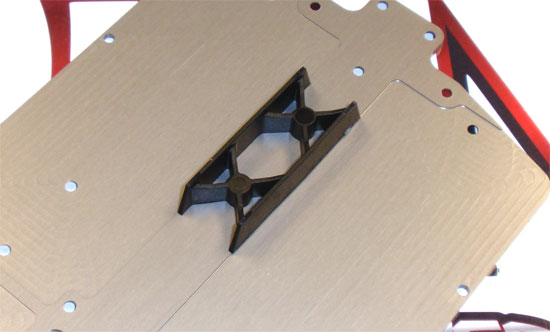
Attach the center battery cradle to the chassis. This will be used with either battery configuration you build.
Step 10
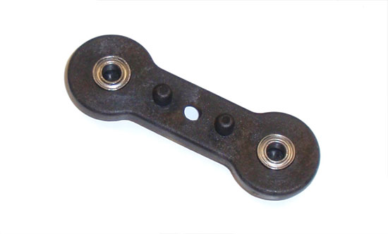
Press the two larger-hole bearings into the steering retainer top.
Step 11
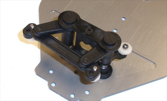
Key the steering retainer top to the steering rack and secure with the 3/8″ screw.
Like I said, pretty simple step. Make sure your steering rack swings freely.
Team Associated B44.3 Online Build – Part 4
In this step we’ll be attaching the gearboxes and suspension arms to the Team Associated B44.3 chassis.
Build Notes:
• The rear bumper is pretty much for looks only. Be careful if you pick it up by this location as it will wildly flex and possibly cause you to drop the car (happened to me the first time).
• The rear bulkhead controls the rear toe of the buggy. When assembling the rear suspension, you’ll need to flex the pin inward to make it fit. It’s a little awkward so my suggestion is to test fit the pin first to see what the assembly process is.
Step 1
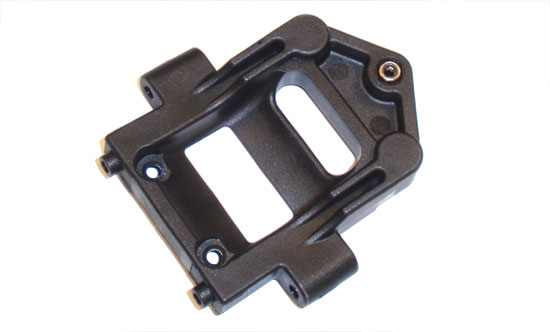
Start off this step by pressing the locknut into the front bulkhead.
Step 2
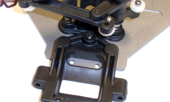
Now attach the front bulkhead to the chassis.
Step 3
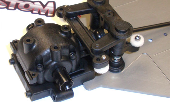
Take your front gearbox (the one with the shorter center CVA), slide the CVA through the opening in the steering retainer column and set into place. Secure with the 2 3/8″ screws.
Step 4
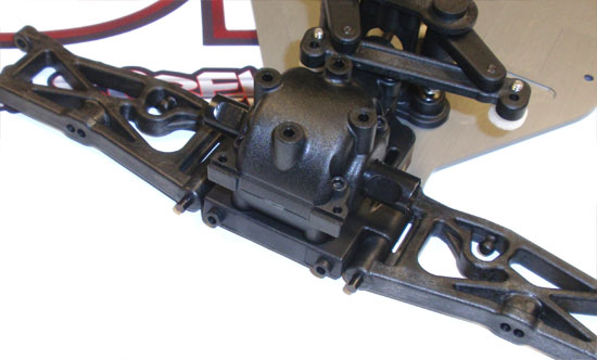
Slide the front arms into place and capture with the pair of hinge pins. Make sure the pins feed all the way into the back of the bulkhead. Note the orientation of the front arms.
Step 5
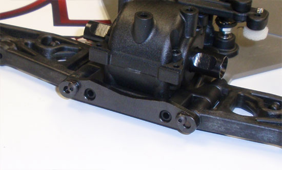
Slide the front hinge pin brace into position and capture the hinge pins with the 2 2-56 screws.
Step 6
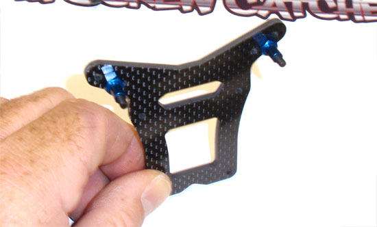
Assemble the front shock tower as shown. It’s not directional so it doens’t matter which way you build it. Don’t forget a light dab of threadlocker on the screws.
Step 7
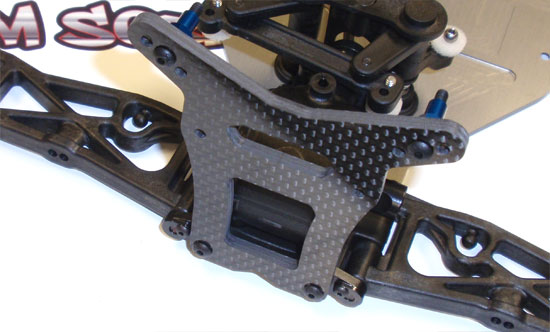
Now attach the front tower to the chassis, shock mounts pointing towards the back of the buggy.
Step 8
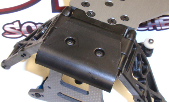
Flip the B44.3 over and attach the front bumper.
Step 9
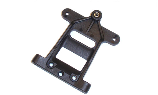
Press the locknut into the rear bulkhead…
Step 10
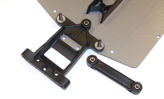
…and attach it to the chassis. Slide the 5/8″ screws through the bulkhead followed by the #4 washers. Press 2 more locknuts into the rear arm mount and attach to the chassis.
Step 11
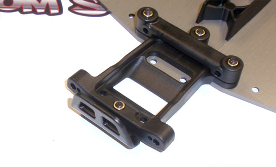
Press a final locknut into the rear bulkhead and attach the rear bumper.
Step 12
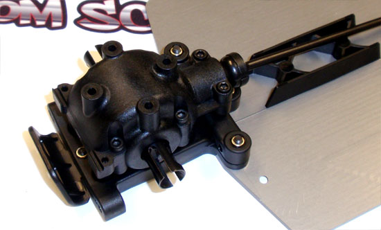
Take the remaining gearbox and attach it to the chassis. Make sure this gearbox has the longer center CVA than the front.
Step 13
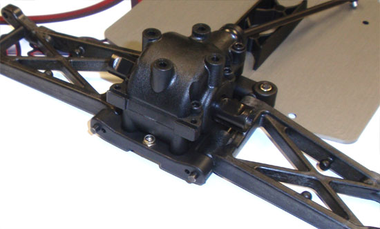
Slip the rear suspension arms into place followed by the hinge pins. You will need to flex the front of the pins towards the centerline of the chassis to make them fit; this is how the inner toe is controlled. Make sure the pins go all the way in (as shown). For some reason I found it much easier to do with the rear bumper off so if you’re having some trouble, give that a try.
Step 14
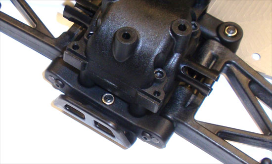
Finally, capture the rear hinge pins with the 2-56 screws. If you removed the rear bumper, you can re-install that now as well.
On a final note, you might check to make sure the front and rear suspension arms move freely up and down. Great job.
Team Associated B44.3 Online Build – Part 5
In this step we’ll be attaching the center bulkhead and installing the center differential.
Build Notes:
• The center bulkheads can be attached in one of two configurations depending on the battery layout you’ve decided to use; saddle packs or a shorty pack.
• The center bulkhead inserts (the ones that hold the center spur) are also different depending on if you are using the included gear diff or optional ball diff/slipper setup. If you are using the stock gear diff, keep the ball diff inserts someplace safe; you may want to switch to that some day.
• The center diff can be installed one of two ways; which way you install it can change the way the pinion mates to it. Be sure to double-check your installation so the pinion meshes correctly with the spur gear.
• The manual shows the motor install with the wire mounting tabs straight up. Don’t install the motor this way; instead, rotate it one set of holes so the mounting tabs are AWAY from the top deck. If you mount the motor as it shows in the manual, the inside-most tab will contact the top deck.
Step 1
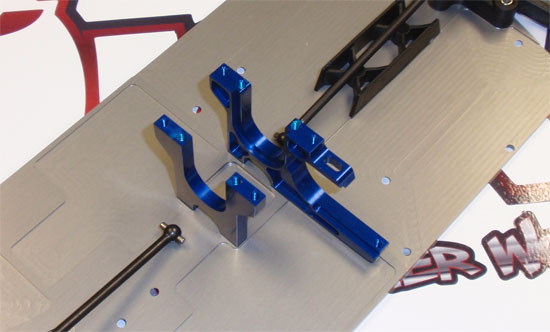
Attach the 2 aluminum center bulkheads to the chassis. As stated in the build notes, these will mount differently depending on what battery configuration you’ve chosen. A light dab of threadlocker is suggested on all 4 screws.
Step 2
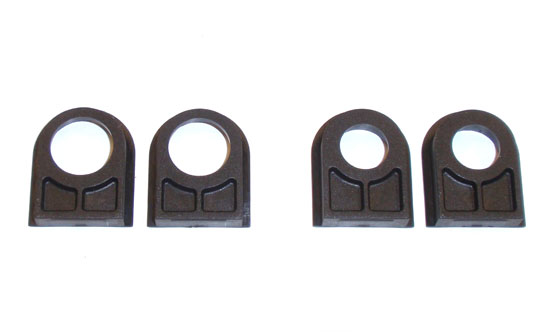
Here are both sets of center diff bearing inserts. The ones on the left are the ones we will be using (gear diff), the ones on the right are for the optional ball diff/slipper clutch.
Step 3
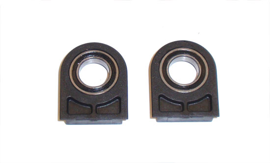
Press the two large ID bearings into the inserts, making sure they are fully seated.
Step 4
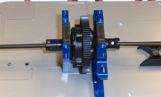
Slip the inserts onto the center diff, making sure the bearings are FACING the diff. Key both CVAs to the diff outdrives and then slowly slide the diff assembly into the center bulkhead, making sure you key the inserts to the grooves. Note the orientation of the spur gear; you want it to be towards the back of the assembly.
Step 5
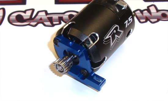
Attach the pinion to the motor and the motor to the motor mount. We’ll configure the pinion placement in a Step 63.
Step 6
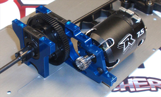
Fit the motor mount assembly into the grooves on the center bulkhead and slide it towards the spur gear.
Step 7
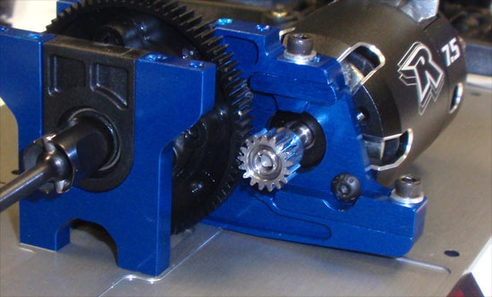
Adjust the pinion so that it’s making full contact with the spur. Slide the motor mount in or out to set the gear mesh and tighten down the 2 3/8″ screws.
Great job. Motor and center bulkhead installed!
Team Associated B44.3 Online Build – Part 6
In this installment of the Team Associated B44.3 build, we’ll be assembling and attaching both the front and rear top decks. This step also includes the rear shock tower, wing mounts and center diff cover.
Build Notes:
• There B44.3 uses a split/top deck design. Take a close look a both of them before you start building. They are directional and have a top and bottom side.
Step 1
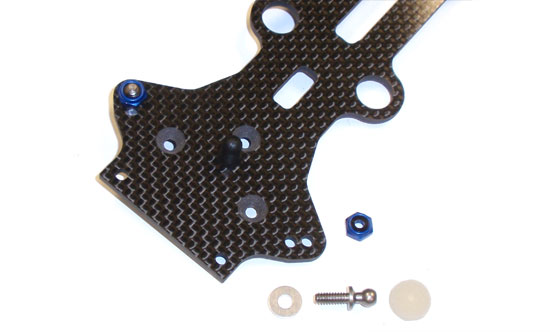
Take the front top deck section and attach the front body mount. Next, attach both of the inner camber link ball studs to the holes as shown. Don’t forget to add a #4 washer under each ball and a foam protector on top.
Step 2
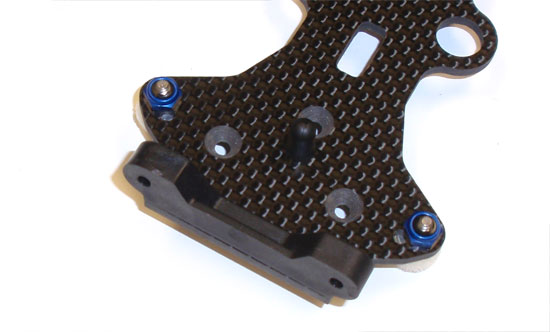
Attach the front shock tower brace to the front top deck…
Step 3
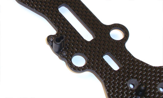
…followed by the antenna mount. The antenna hole should be facing out so that the antenna will match up with the hole you’ll be blindly cutting into the body.
Step 4
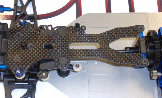
Attach the assembled top deck to the front of the car. Add a dab of threadlocker to the screws that feed into the center, aluminum bulkhead. Do not tighten down just yet.
Step 5
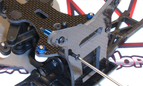
Now secure the front shock tower to the brace on the top deck. After you’ve tightened this down, go ahead and finish tightening down the screws on the top deck.
Step 6
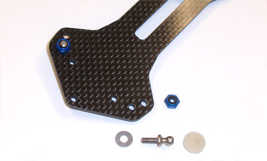
Find the rear top deck and attach the pair of inner camber link ball studs. A #4 washer goes under these as well (as does the foam protector).
Step 7
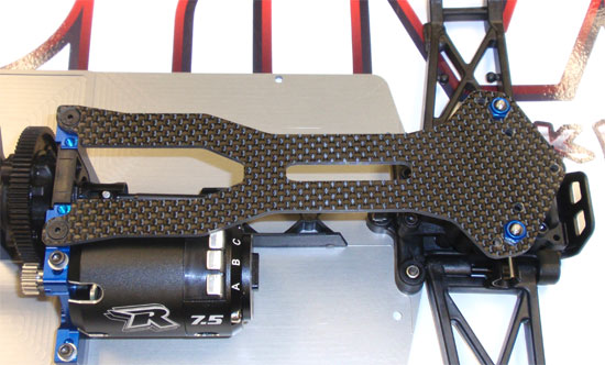
Attach the rear top deck to the car. Apply a dab of threadlocker to the screws that attach to the center, aluminum bulkhead. Don’t tighten down all the way just yet.
Step 8
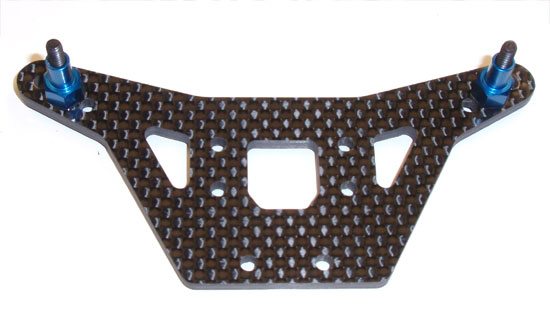
Time to assemble the rear shock tower. Start by adding the upper shock mount screws. The tower is not directional so it doesn’t matter which side you start with.
Step 9
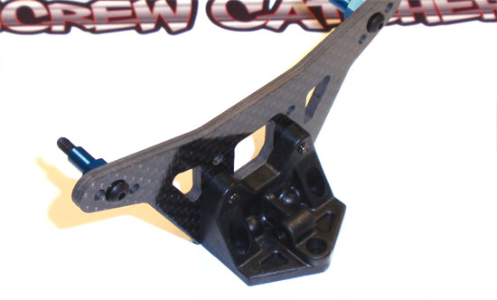
Attach the shock tower mount to the tower as shown.
Step 10
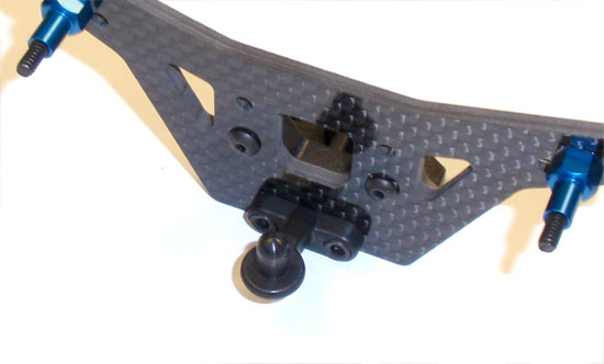
Attach the rear body mount to the opposite side of the tower.
Step 11
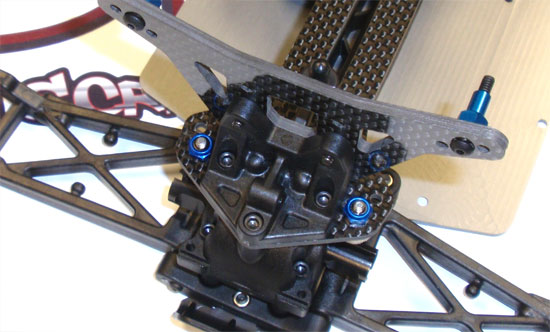
Finally, attach the rear shock tower assembly to the top deck. Once this is secure, you can finish tightening down the rest of the rear top deck screws.
Step 12
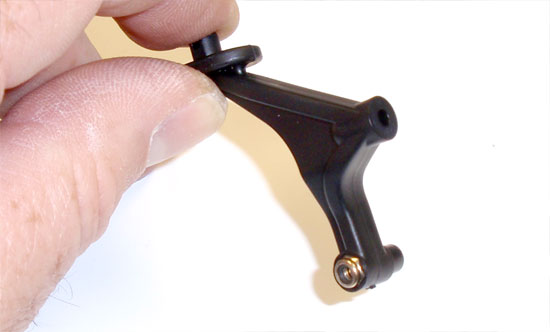
The rear wing mount is next, but note that the two pieces are not the same. Take the one with the ‘hex’ in it an press a locknut into place.
Step 13
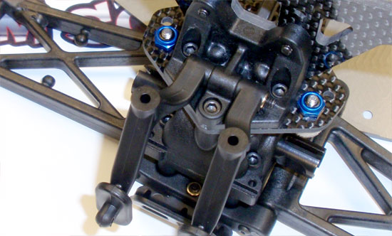
Place both wing mounts into position and slide the 7/8″ screw through, tightening it down to into the locknut to secure the mounts. I pivoted the mounts down to make them equal and easier to manage while tightening the screw.
Step 14
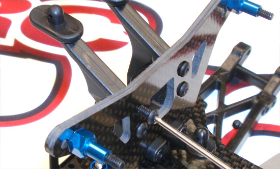
Now swing both wing mounts up and attach to the rear tower.
Step 15
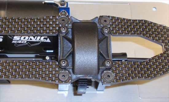
The final step is to set the center bulkhead cover into place and secure. A dab of threadlocker will help here.
Nice job. Both top decks in place!
Team Associated B44.3 Online Build – Part 7
In Part 7 of our Team Associated B44.3 build, we’ll be assembling the outer suspension parts, the turnbuckles and connecting the two together.
Build Notes:
• None.
Step 1
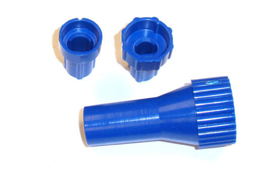
Building turnbuckles can be a pain in the butt, but thankfully there are a few tools that make this task easier. Duratrax offers this ball end driver that holds onto the ball cup, making it easier to screw onto the turnbuckle. There are also a myriad of quality turnbuckle wrenches on the market that will make this job easier. I’ve listed some at the bottom of this post.
Step 2
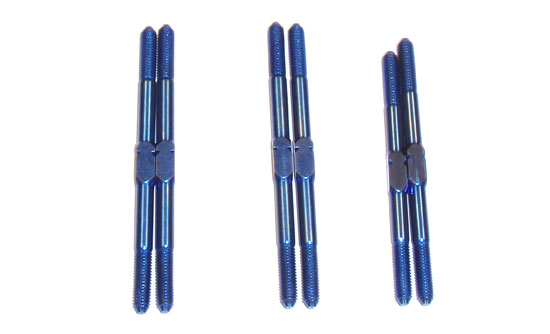
The next step is to separate the turnbuckles. As you see, there are 4 2″ turnbuckles and 2 1.77″ ones. The 4 longer ones are for the front and rear camber while the 2 shorter ones are for the steering. Just make sure you use the right ones during the right steps.
Step 3
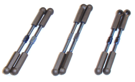
Assemble the 6 turnbuckles as shown, using the lengths suggested in the manual. I started with these lengths but did manipulate them once I got running on the track. After you build them keep the separated; they are build as a left and right for their intended location.
Step 4
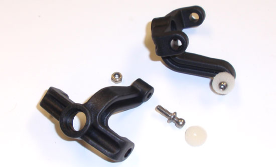
Press a locknut into the bottom of the steering arm and screw the silver ball stud in. Don’t forget your foam thingy.
Step 5
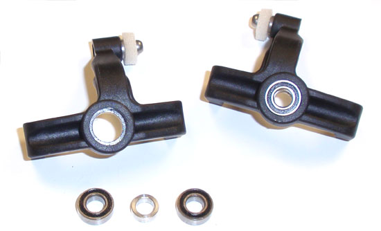
Press two bearings into each steering arm. Insert the crush tube in between them.
Step 6
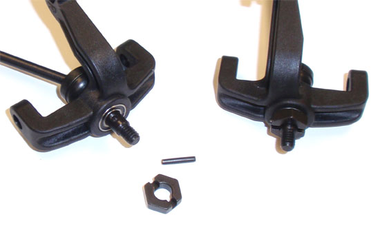
Slide your assembled front axle through the steering arm. Press the drive hex onto the axle, with the notches facing out, and secure it in place with the drive pin.
Step 7
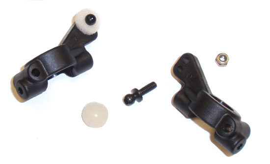
Assemble the pair of caster blocks as shown. Both blocks are the same, just be sure to build them as a left and right.
Step 8
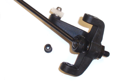
Carefully fit the two hat washers into position in the steering arm. They will fall out quite easily so be sure to keep the arm sideways at all times.
Step 9
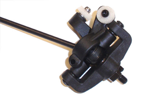
Slide the caster block into position, keeping an eye on the hat washers to make sure they stay in place. Secure the caster block with the pair of 7/16″ screws. Do not overtighten … the steering arm should swivel back and forth with ease.
Step 10
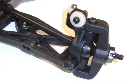
Attach the steering arm assembly to the front arm by sliding the hinge pin into place. Secure the hinge pin with the 2-56 screw. Not the orientation of the steering arm.
Step 11
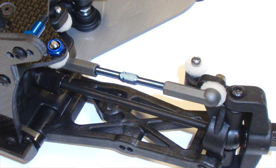
Find your front camber link turnbuckle and pop them into place (you did keep them separate, right?).
Step 12
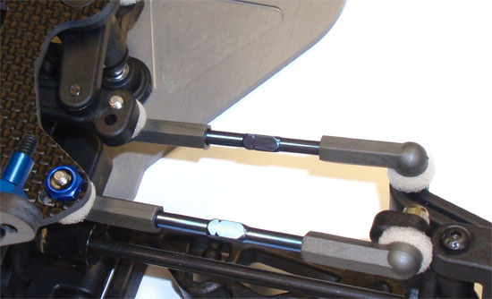
Find your steering link turnbuckles and pop them into place as well. Make sure the notches in the turnbuckles are all facing the same way.
Step 13
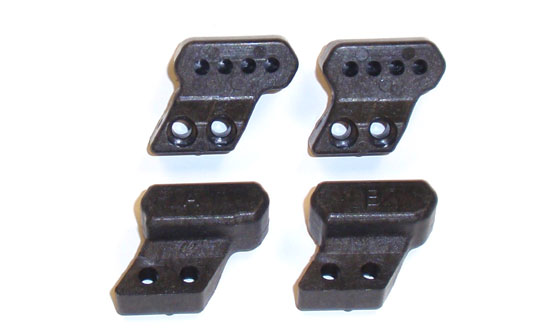
The rear hubs use molded camber link towers for adjustment. AE includes two of them; an A and a B tower. Grab both A towers (but keep the B’s in case you want to make any changes at the track).
Step 14
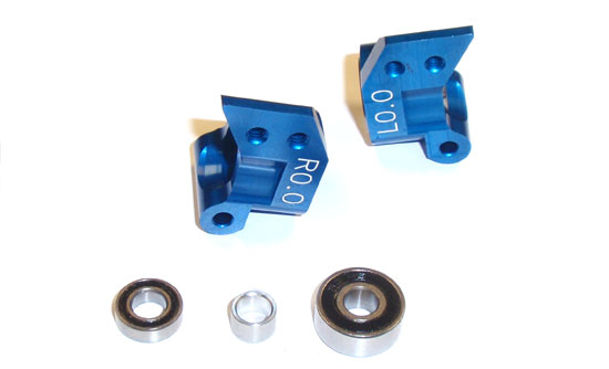
Insert the bearings and crush tubes into the rear hubs.
Step 15
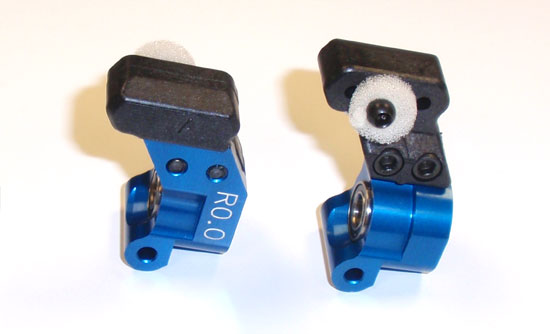
Assemble your rear hubs as shown using the A towers.
Step 16
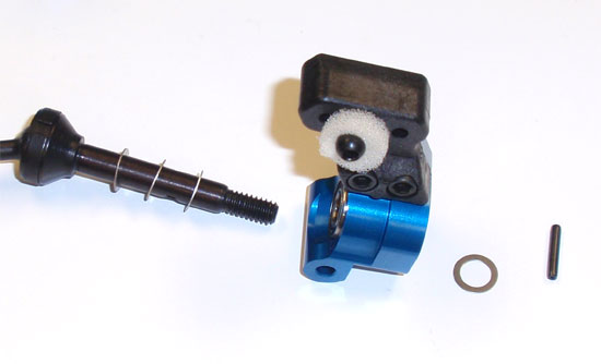
Add 3 3/16 shims to the rear axle and slide it though the hub assembly, followed by another 3/16 shim and finally the roll pin.
Step 17
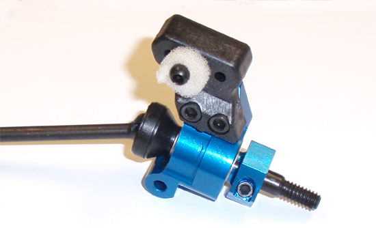
Slide the 12mm clamping hex onto the shaft and key it to the roll pin. Use the 2-56 screw to pin the hex into place.
Step 18
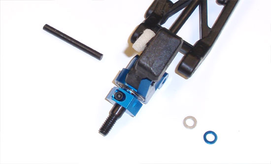
Attach your rear hub assembly to the rear suspension arm using the rear hinge pin. You’ll be adding a pair of wheelbase washers as well, both behind the hub. Use the 2-56 screw to capture the rear hinge pin.
Step 19
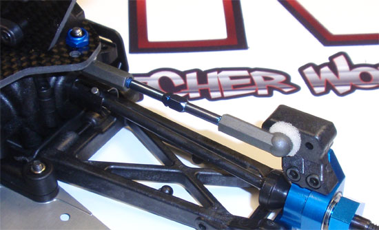
Find your rear camber link turnbuckles and pop them into place, matching their direction to the front (using the notches).
Nice long step but we got a lot accomplished. Double check your suspension to make sure everything swings freely.
Here are a few items that will make this build (and future builds) a little bit easier.
Team Associated B44.3 Online Build – Part 8
I’ve broken out the rear anti-roll bar steps in our Team Associated B44.3 build into it’s own part for 2 reasons; 1) it didn’t fit with anything else and, 2) you look like you need a small break in the action. Three steps; easy peasy.
Build Notes:
• None. Again, it’s only 3 steps.
Step 1
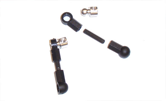
Build 2 of the anti-roll bar links to the lengths shown in the manual. Pop the anti-roll bar pivot into the open-ended ball cup and rotate it slightly. Mirror this one the other side.
Step 2
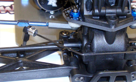
Pop the anti-roll bar link onto the front ball on the suspension arm. Take your anti-roll bar (whichever one you are using; AE supplies 2) and slide it into the pivot ball, securing it with the setscrew. You want to make sure that the anti-roll bar does not extend out past the pivot ball. Attach both sides.
Step 3
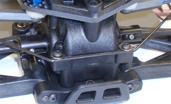
Set the anti-roll bar into the groove and secure it with the 2 2-56 screws (and washers). Do not overtigthen; you want the screws and washers to keep the anti-roll bar in place, not hinder it’s movement.
There ya have it. Three easy steps and a connected anti-roll bar.
Team Associated B44.3 Online Build – Part 9
We’ll be building the shocks in Part 9 of the Team Associated B44.3 build. The buggy uses the A-Team’s awesome V2 12mm Big Bore aluminum shocks which feature 3mm shafts and molded caps with bleed screws. These shocks are a breeze to build and provide excellent damping on the track.
Build Notes:
• First and foremost, we’ll be dealing with shock fluid so have some rags handy to clean up any extra oil that might leak or bleed out of the shocks.
Step 1
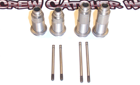
Before we start the build, let’s get aquainted with the parts so you don’t mix things up. Here you’ll see the shock bodies and the shafts. Short up front, long out back.
Step 2
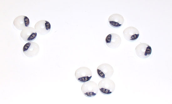
The shocks come with a few different hole-sized pistons as well. I take a Sharpie and color over the numbers so I can see them better, both in and out of the shocks.
Step 3
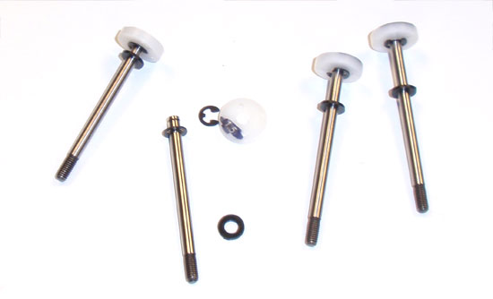
Now that we’ve identified the parts, let’s start putting the shocks together. Snap an e-clip into the lower groove on the shaft, followed by the piston (1.5 in the front, 1.7 in the rear) and then the other e-clip. Slide a .030 washer onto the shaft of each shock as well.
Step 4
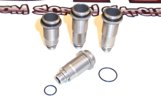
Flex a 12mm o-ring over the top of the shock opening and a VCS3 o-ring over the lower shock opening.
Step 5
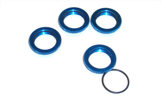
Fit the other 12mm o-rings into the threaded collar. The instructions mention this step a little later, but I like to do it early before I get shock fluid on my fingers (making it harder to deal with the o-ring).
Step 6
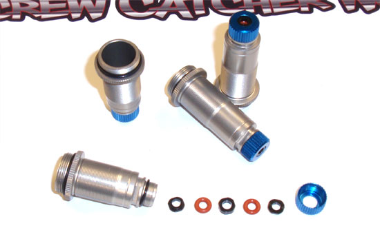
Assemble the bottom cartridge area of the shock; in this order – shock hat bushing, o-ring, shock spacer, o-ring, bottom shock hat bushing and then the bottom shock cap. Make sure both hat bushings are facing away from the o-rings.
Step 7
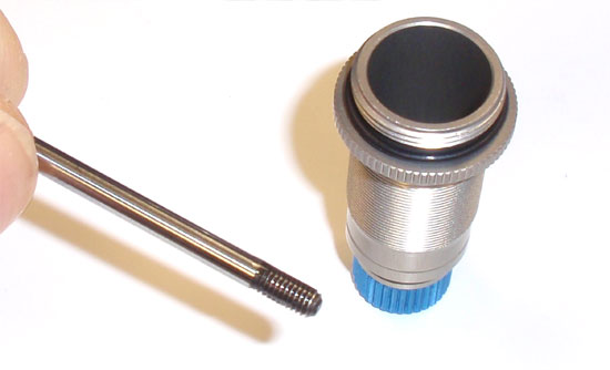
Put a drop of shock fluid on the shaft threads and install. Make sure you’re putting a front shaft (short) into a front shock body (short); longer shaft (rear) into the longer body (rear).
Step 8
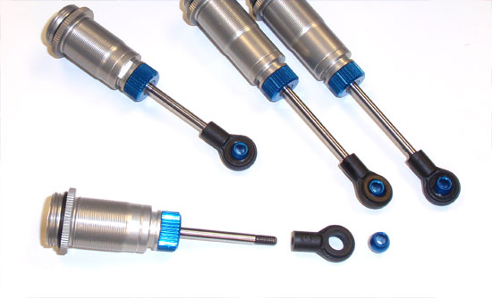
Thread the shock eyelet onto the shaft and pop the FT pivot balls into place. Make the gap between the shock eyelet and the bottom shock cap equal (the fronts the same, the rears the same).
Step 9
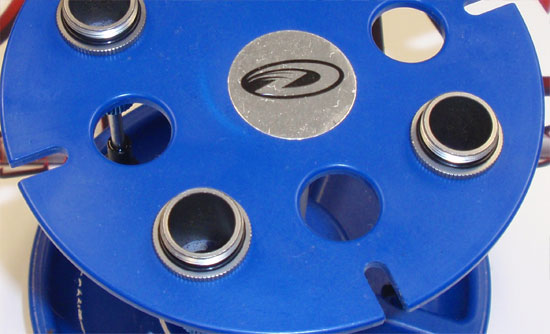
Fill the shocks with oil. You’ll want to SLOWLY move the shock shafts up and down to get any air bubbles out from under the piston. Set the shocks in a stand (like this Duratrax one) and let all the bubbles rise to the top.
Step 10
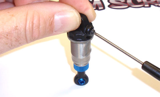
Pre-thread the 2-56 screw into the shock cap, then remove. Screw the shock cap onto the shock. Compressing the shock (as shown) will cause any excess oil to leak out of the cap. When the shock is completely compressed, thread the 2-56 screw back into place. Clean off any oil that leaked out of the shocks.
Step 11
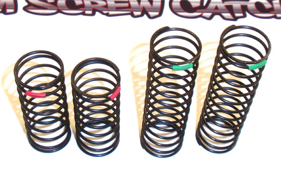
The B44.3 comes with red front springs (3.90lb) and green rears (2.00lb).
Step 12
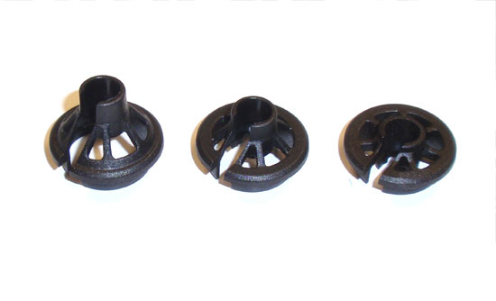
It also comes with 3 different offsets of lower spring retainers (from left to right – 9mm, 5mm, 0mm). We’ll be using the 5mm retainers all the way around.
Step 13
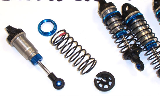
Thread the upper collar onto the shock followed by the spring and lower spring retainer.
Step 14
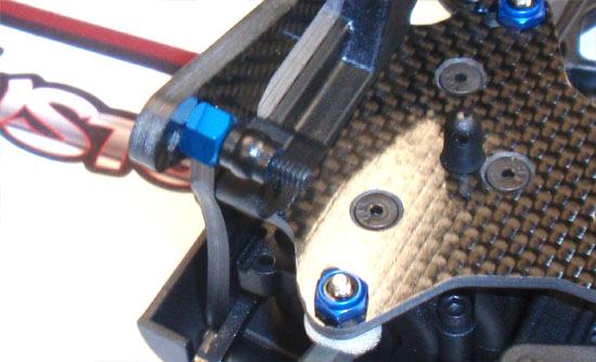
Assemble the upper shock mounts using the center hole.
Step 15
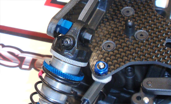
Attach the upper shock, using the plastic shock nut to secure it in place.
Step 16
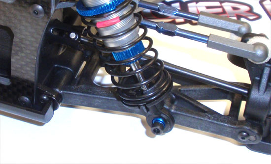
Attach the lower part of the shock to the arm, using the outside hole. Build both sides.
Step 17
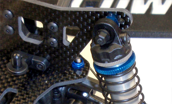
Use the same method in the rear, attaching the shock to the tower using the middle hole.
Step 18
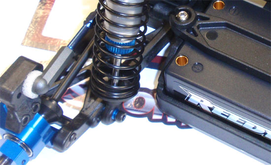
Same mounting to the arm, using the inner hole. Build both sides.
Big Bore shocks complete and mounted on your B44.3.
I’ve added a few parts that make shock building a little easier. Pick one up; pick them all up!
Team Associated B44.3 Online Build – Part 10
The final major step in the Team Associated B44.3 build is installing the electronics.
Build Notes:
• The B44.3 allows you to build the car using either a saddle-pack setup or a single shorty LiPo battery. I chose to use the single shorty so the build steps will reflect that.
• I’ve included a few build items at the bottom of the list that I use that make electronics installation a whole lot easier. They include a quality soldering iron (with adjustable heat), a ‘helping hands’ soldering aid and a good roll of double-sided tape.
Step 1
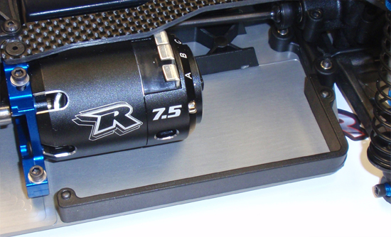
Attach the left side rail as shown.
Step 2
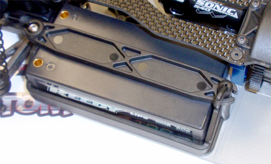
Attach the battery cradle, ball joint and 4-40 set screw. Insert the battery and adjust the ball joint and set screw until the battery strap lays on top of the battery. Now install the battery strap lock and rotate it into place.
Step 3
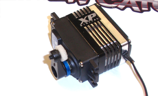
Assemble the servo horn and attach it to the servo.
Step 4
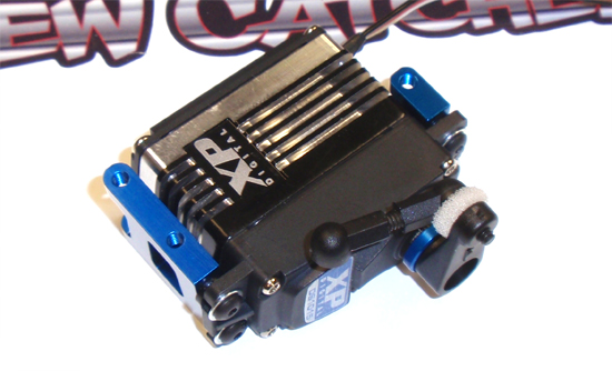
Attach the floating servo mounts but do not tighten just yet. Assemble the servo drag link and pop it onto the servo horn.
Step 5
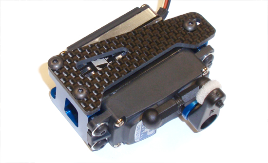
Attach the floating servo brace onto the servo mounts. A dab of threadlock should be used. Once secure, tighten the 4 servo mounts screws from Step 122.
Step 6
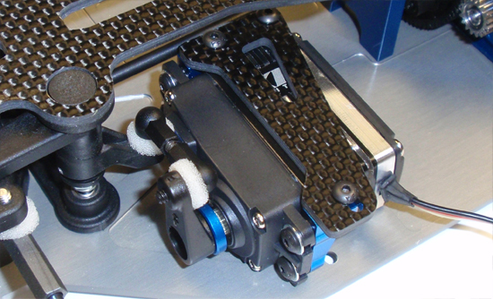
Attach the floating servo mount assembly to the chassis and pop the servo drag link onto the steering rack.
Step 7
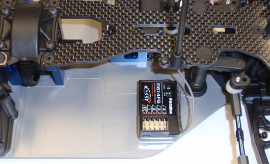
Using a quality double-sided tape, stick the receiver to the chassis and route the receiver wire up through the antenna mount. Add the antenna tube and cap.
Step 8
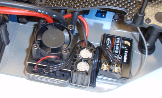
Using a quality double-sided tape, stick the ESC to the chassis. The Reedy Blackbox uses external capacitors so those were also attached to the chassis. Feed your wires over to the battery (either above or below the top deck). Feed the motor wires over to the motor and solder into place. Don’t forget to attach the sensor wire.
That’s it. Super easy!
Team Associated B44.3 Online Build – Part 11
Here we are, the final step in the Team Associated B44.3 build. We’ll be gluing up some tires and attaching them as well as mounting the wing and body.
Build Notes:
• As always, care must be taken when using CA glue of any kind.
• If you’re up for trying to do a wicked paint job yourself, I’ve added a few links at the bottom for paint and painting supplies. Give it a go if you’ve never tried it before.
Step 1
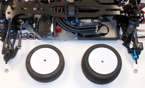
Stuff the inserts into the tires and stretch the tires over the wheels. Using a quality CA glue, glue the tires together. You can follow this guide if you’re unsure how to do this: Gluing Short Course Tires. Slightly different but the process is the same. Set them aside to dry.
Step 2
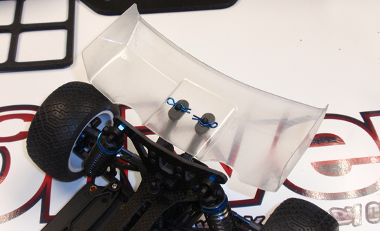
Place the wing shims on the wing mounts. The ‘wedge’ should face forward. Using a reamer, drill holes in the wing and set on the wing mounts, securing with the pair of Factory Team blue body clips.
Step 3
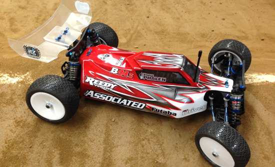
Trim your painted body using a good set of scissors. Ream 2 holes for the body mounts and set in place, securing with the pair of FT body clips. Align your glued tires with the hexes on the axles and slide into place, making sure the narrow wheel assembly goes on the front, the wider set on the rear. Use the low-profile 8-32 wheelnuts on the front and the standard 8-32 ones on the rear.
THAT’S IT! You’re Team Associated B44.3 should be prepped and ready to hit the track!

