
Vaterra Ascender K5 Blazer Online Build
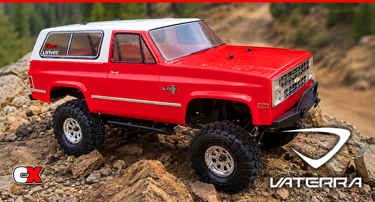
Trail trucks are quickly becoming one of those must-have vehicles in everyone’s RC stable. With massive aftermarket support and uber-scale realism, there’s definitely a growing market for these vehicles. Vaterra is looking to put it’s stamp on the scaler-scene with the release of their Ascender, a new ground-up design aimed straight for the trails.
This truck features a beautiful 1986 Chevrolet K5 Blazer body, chrome wheels, soft Super Swamper tires, multi-link solid axle suspension, threaded shocks and a whole slew of other goodies that every trail trucker might want.
We’ve opened the box, gathered our accessories and got our build on. Enjoy.
Vaterra Ascender K5 Blazer Online Build – Part 1
Part 1 of the Vaterra Ascender build revolves around the transmission. The Vaterra transmission is similar to other trail truck’s gearboxes so if you’ve built one before, this should be a walk in the park. If this is your first time, pay special attention to my notes to make the build roll along smoothly.
Build Notes:
• You will need threadlocking compound during this build. In Step 4 I give you a little tip on how to manage this. Give that a look before moving on.
• The slipper clutch install is a bit tricky. Patience is needed here to make sure the slipper pads stay correctly keyed to the slipper plates.
• Sliding the spiral axle-pin retainer into place is also a bit tricky. Take your time and follow my tip and you’ll be putting all of them on like a pro.
Step 1
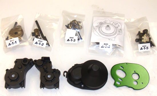
We start off the build with a basic overview of the bag layouts that Vaterra has put in place. As you can see, they’ve labeled the bags A-1-1 for the first bag to use, A-1-2 for the second and so on. I found this to be pretty accurate when assembling the Ascender as it only allows access to the parts you need for a particular step.
Step 2
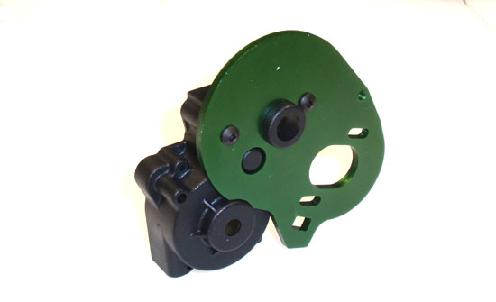
On with the build. Start by attaching the motor plate to the gearbox half as shown.
Step 3
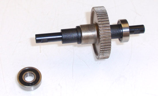
Vaterra has supplied a solid, one piece lower transmission gear with the Ascender. Slide it onto the shaft followed by a plastic hat washer and bearing. Make sure you slide the hat washers on the correct way.
Step 4
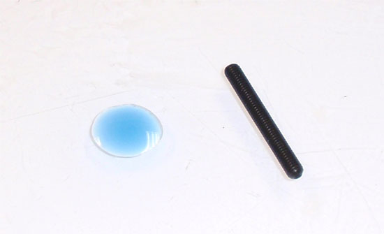
As I mentioned in the build notes, some steps require you to use threadlocker. I like to put a small puddle of the blue threadlocker onto my plastic work area and dip from it. This allows me to control how much I put on.
Step 5
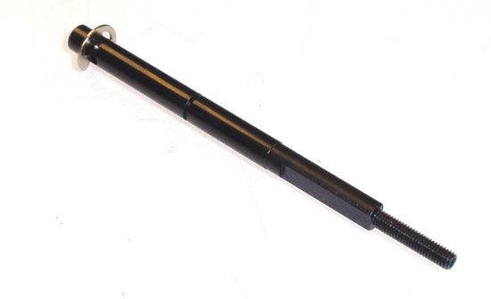
Dip the long setscrew into the threadlocker and insert it into the top shaft. Pop one of the e-clips into the groove at the other end.
Step 6
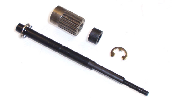
Slide the pin into the hole of the top shaft at the e-clip end, then slide the gear up and key it to the pin. Slide the plastic spacer on and capture both parts with another e-clip.
Step 7
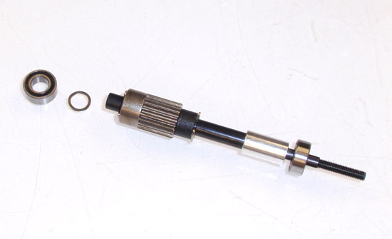
On the short end of the top shaft, slide the small washer followed by the bearing. On the opposite end, slide the metal spacer onto the top shaft followed by the other bearing.
Step 8
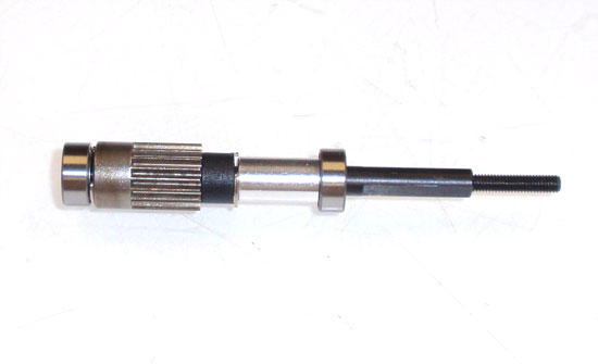
This is how your assembled top shaft should look. Temporarily set it aside.
Step 9
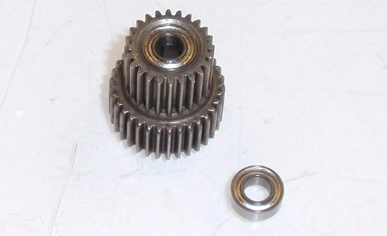
Slide a bearing into each end of the transmission’s center gear.
Step 10
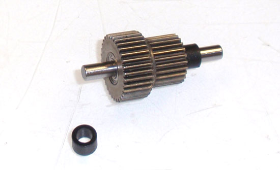
Slide the shaft through the center gear followed by a plastic spacer on each end. Set aside.
Step 11
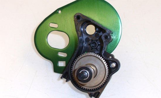
Slide the lower transmission gear assembly into the case assembly, short side first.
Step 12
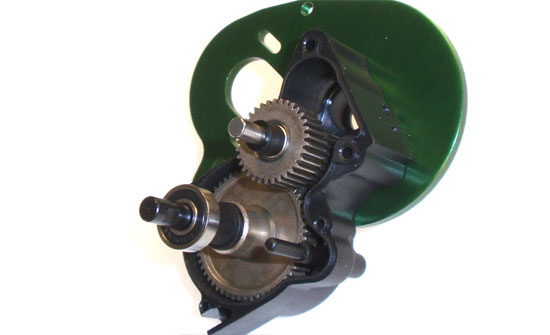
Insert the center gear assembly into the case as shown. Also insert the metal guide shaft into the case. Note the direction.
Step 13
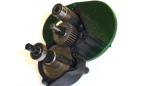
Finally, slide the top shaft into place. Make sure that, when you insert all the gears, all of the bearings and spacers remain on the shafts.
Step 14
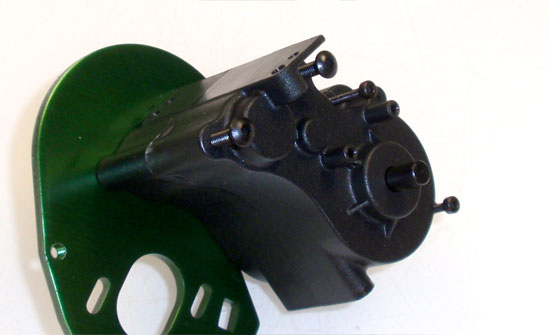
Slide the other transmission half into place and secure with the 4 screws. Snug them down and then give the top shaft a spin. If it spins freely, tighten the screws down. If they top shaft sticks or doesn’t rotate, disassemble and make sure you’ve assembled the gear sets correctly.
Step 15
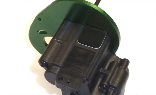
Place the sticker onto the top of the transmission as shown. This helps keep and debris out of the transmission.
Step 16
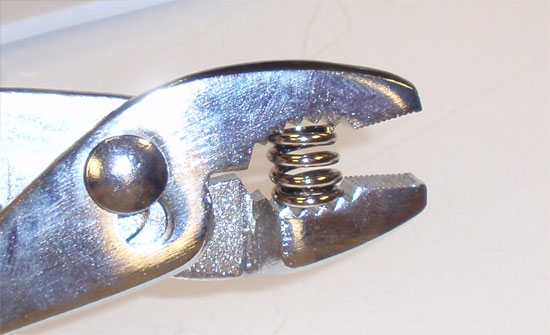
We’re going to install the slipper clutch now but need to start by pre-compressing the slipper spring. Compress 2 or 3 times.
Step 17
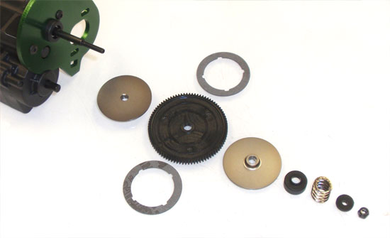
A quick look at how this will all go together. I would suggest laying out the pieces prior to assembly as one of your hands will be busy holding the transmission.
Step 18
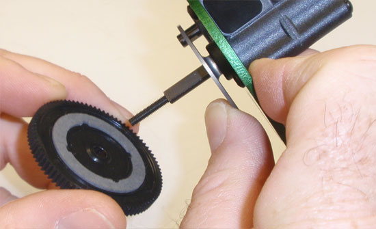
Place a slipper pad onto the gear, making sure the notches line up with the cutouts in the pad. Side a slipper plate onto the top shaft and, while holding the transmission as shown, slide the gear onto the shaft; pad side first. This part is a little tricky because the pad doesn’t ‘stick’ to the gear, so it moves around quite easily. Assembling in this ‘upside-down’ fashion will help keep it keyed the gear.
Step 19
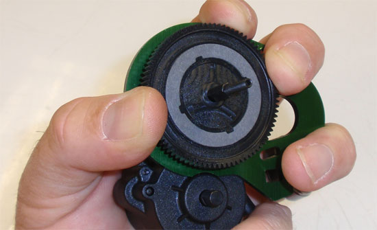
Once you’re SLOWLY seated the gear (and the slipper pad is correctly keyed to the gear), flip the assembly over and hold as shown. This will keep the gear from moving and the slipper pad from becoming dislodged. Now place the second slipper pad into place, keying the notches to the cutouts as we did before.
Step 20
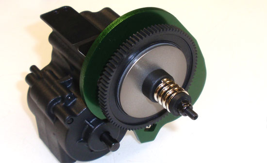
While still holding the gear firmly, slide the second slipper plate onto the top shaft followed by the large spring retainer, the slipper spring, the smaller spring retainer and the locknut. While not in the manual, a support page for the Ascender suggests tightening the slipper all the way down and then backing off 5 1/2 turns.
Step 21
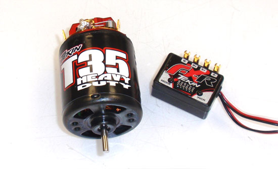
For mojo, I’ll be using Tekin’s T-35 Heavy Duty Brushed 540 Motor and FX-R Brushed ESC. I’ve used this before and it’s a pretty stellar combo for crawling.
Step 22
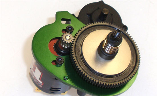
Slide the large, red ‘washer’ onto the motor, lining up the holes with the mounting holes on the motor. Attach the motor using the 2 M3x8mm screws. Install the pinion and set the gear mesh as shown.
Step 23
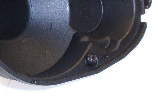
Press the 8mm screw through the hole in the gear cover and slide the small o-ring over it. The Ascender’s gear cover doesn’t have a hole to adjust the slipper so you have to remove the cover each time you want to make an adjustment. Kind of bummed about that since, to me, the ‘hole’ method is what I’ve been accustomed to for years. On the other hand, once you adjust it there really should be much of a need to do it again.
Step 24
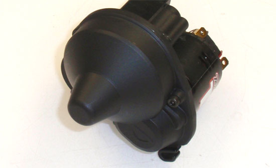
Set the cover into place and tighten the screw.
Step 25
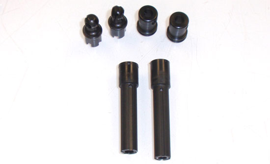
You’ll notice as we build the center driveshafts that there are two lengths. The shorter, plastic slider shaft goes to the front while the longer to the rear.
Step 26
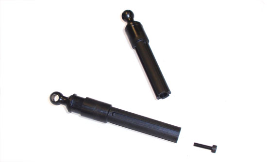
Match the flat spots on the outside of the metal coupler to the flat spots IN the slider shaft and press together. Dip the 10mm screw in your puddle of threadlocker and assemble.
Step 27
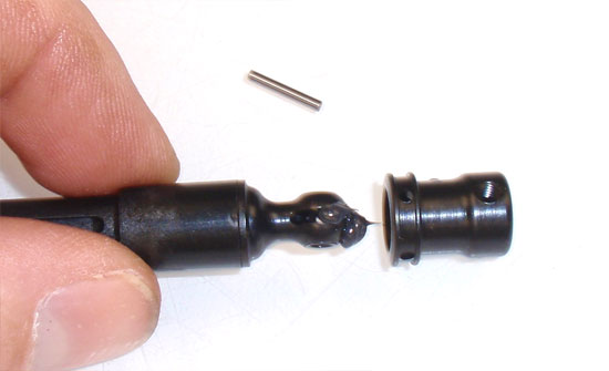
Goop some black grease onto the inner coupler and insert into the outer coupler. Slide the pin through the assembly.
Step 28
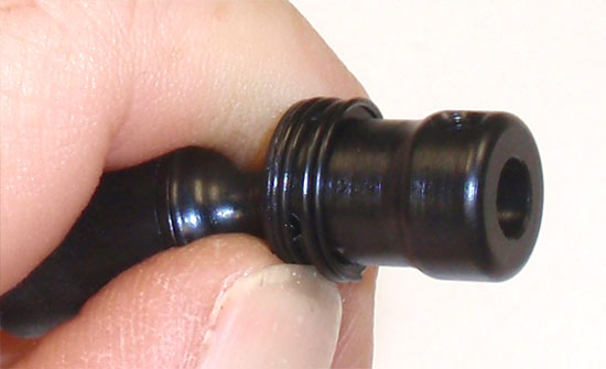
Now, the tricky part. This took me a few minutes to figure out but I found a super easy solution to get these on. Start by slide the spiral retainer over the outer coupler. Take one end the spiral coupler and pop it into it’s final groove area. Using your fingernail, hold it in place and slowly rotate the outer coupler. This will spiral the retainer into it’s final mounting location. Of course, this will only work if you have nails; if you don’t ask your girlfriend/wife/mom if she’ll lend you a hand…or a nail.
Step 29
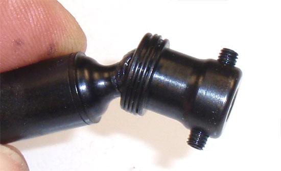
Dip the setscrews into the threadlocker and thread them into each side of the outer coupler as shown (do not tighten down yet). Notice the ‘groovy’ spiral retainer in place.
Step 30
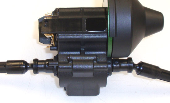
Slide both axle assemblies onto the output shaft of the lower transmission gear and tighten down.
Booyah! Transmission complete! Great job.
Vaterra Ascender K5 Blazer Online Build – Part 2
In Part 2 of the Vaterra Ascender K5 build, we’ll be working on the front axle. This includes the axle, gears and steering system. The K5 uses a standardized front solid axle but has a few features that set it apart; 1) the front axle is a single piece, meaning you won’t be putting two-halves together. Secondly, the steering uses aluminum link instead of plastic. Finally, there is a panhard rod to help manage the front end, however we won’t be attaching that until a later step.
Build Notes:
• Threadlocking compound is required for this step as well. Have your ‘puddle’ ready.
• The manual has you building some of the axle in a certain order. I found a few easier steps and listed them during the build. You can follow either one.
Step 1
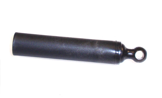
Our first step is to assemble the front slider shaft. Since you’ve already experienced this build in Part 1 (the Transmission), I won’t go into detail with this.
Step 2
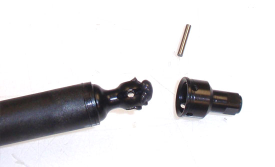
Apply some black grease to the inner coupler, slide the out coupler over it and press the pin through the holes.
Step 3
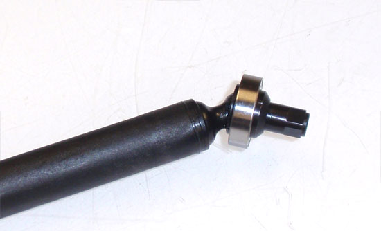
Vaterra doesn’t use a set screw to hold the pin in place; instead it uses a bearing. I like this method alot better!
Step 4
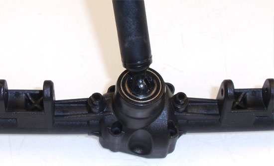
Press the axle assembly into place as shown, making sure the bearing is fully seated into the axle housing.
Step 5
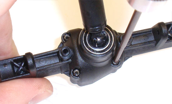
Teka the black M2 locknuts and press them into place in the axle housing. The fit is pretty tight don’t worry about them falling out. Yes, this is out of step according to the manual but I found it easier during final assembly to already have these installed.
Step 6
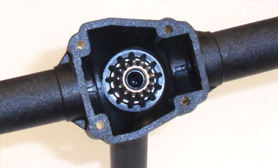
Flip the axle around and press a second bearing into place. Follow that up with the sun gear. Make sure the gear is seated all the way down on the shaft.
Step 7
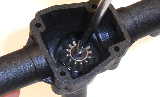
Dab a bit of threadlocker onto the retaining screw and secure the sun gear.
Step 8
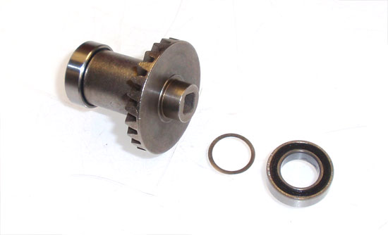
Take your solid, one-piece spool assembly (LOVE that it’s one-piece) and slide a shim and washer on both ends. Your instructions may now show the washer but, again, an online ‘manual fix’ shows this as part of the build.
Step 9
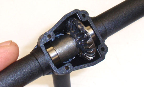
Set the spool into the axle housing and apply some black grease to the gear. Don’t worry about putting to much grease … this is used to help protect the gears during use.
Step 10
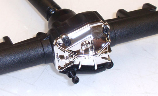
Slide the chrome pumpkin cover and cover protector onto the axle and secure with the 4 screws. Note that there are two different lengths of screws used here; use the shorter ones up top.
Step 11
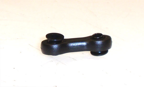
Assemble the short link. This link is used to attach the front axle to the floating battery tray. Note the direction of the two balls.
Step 12
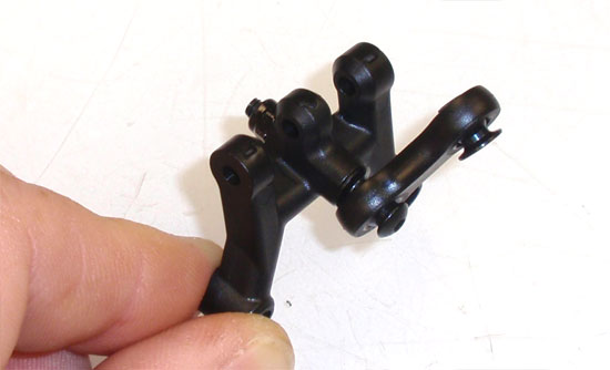
Attach the link to the link brace…
Step 13
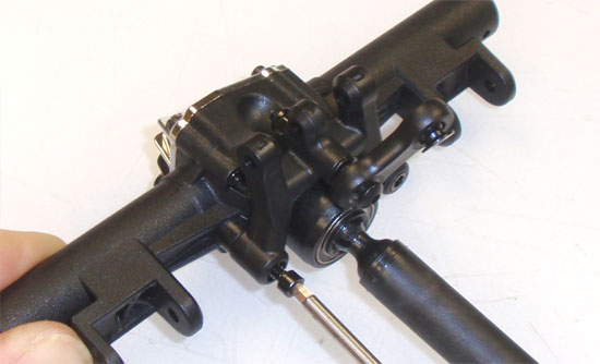
…and then attach the link brace to the front axle.
Step 14
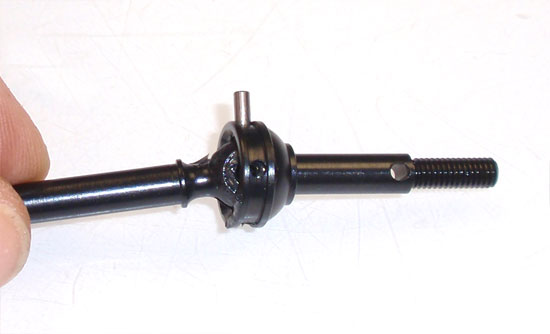
Build the axle as shown. Again, we’ve already built one of these so we don’t need to go into detail about it … I hope.
Step 15
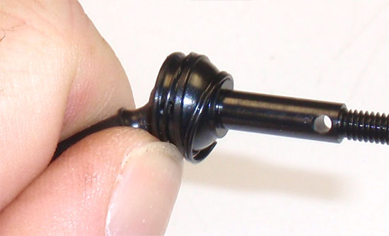
Use the ‘Phalen-fingernail method’ to attach the spiral retainer. Feel free to use the term ‘Phalen-fingernail method’. Build 2 of these.
Step 16
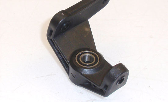
Assemble the left spindle by pressing a bearing into each side (don’t forget the crush tube between them). Take 2 of the hat washers and slide them into the upper and lower holes in the spindle as shown.
Step 17
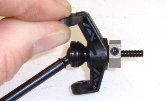
Rest the spindle on it’s side and carefully push an assembled axle through it. Slide the wheel hex into place and, while lining up the hole in the hex and the hole in the axle, secure with the long setscrew. The reason you want to put the hat washers in prior to this assembly is that they can be a bit difficult to insert after if you have sausage fingers. The fit it tight enough to keep them in place; just make sure you assemble with the spindle laying sideways.
Step 18
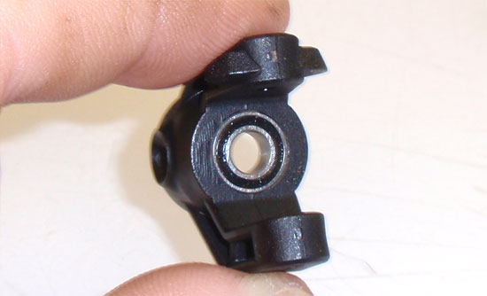
This outer bearing was a bugger to work with as well, but I found if you pressed it into the axle carrier first it was much more manageable. Just press it flush with the piece as shown. Note the orientation of the carrier; the ‘stops’ will be at the top.
Step 19
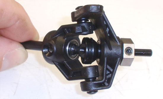
Slide the assembled axle carrier onto the axle and into place with the steering spindle. Secure with the 2 M3x12mm screws. DO NOT OVERTIGHTEN! Snug them down and then rotate the spindle. If it is tight, back the screws off slightly and try again. You want the spindle to move as freely as possible.
Step 20
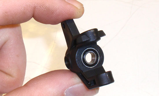
Build the right side spindle like we did in Steps 46-47. As you can see here, we press the outer bearing flush into the right side axle carrier (not the panhard rod mounting tab). You can then assemble the steering as we did in Step 49.
Step 21
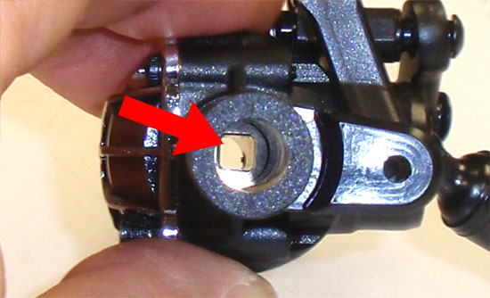
Keying the axle assembly to the spool is a little tricky but I found a somewhat easy way to do this. This picture shows the square opening in the spool you’re trying to mate the axle to. Just keep that in mind.
Step 22
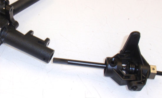
Take your axle assembly and slide it into the axle housing as far as it will go.
Step 23
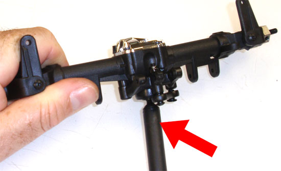
Using one hand to apply a small amount of pressure, press the axle assembly against the axle housing. Now slowly twist the slider shaft (with the red arrow) until the axle ‘slips’ into the spool. Do this with both sides, noting the orientation of the steering assemblies with the axle (make sure you get the right on the right and the left on the left).
Step 24
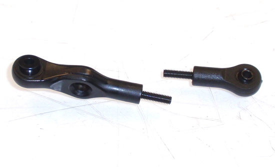
Build two rod ends as shown. This is for the lower steering link (the link that goes from one steering knuckle to the other).
Step 25
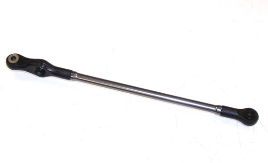
Assemble, making sure you use a dab of threadlocker on the setscrews.
Step 26
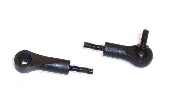
Build two more rod ends. These are for the upper steering link (the link that goes from the servo to the steering assembly).
Step 27
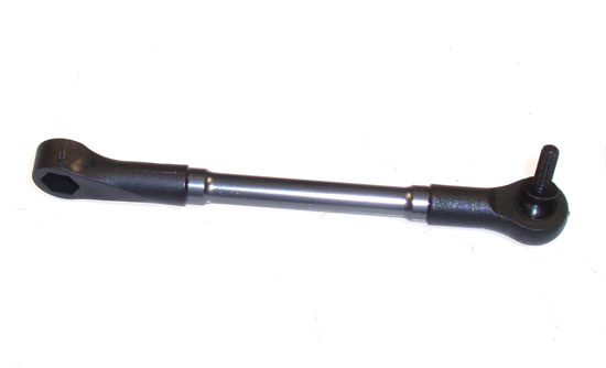
Assemble, making sure you use a dab of threadlocker on the setscrews. Also note the orientation of the two ends.
Step 28
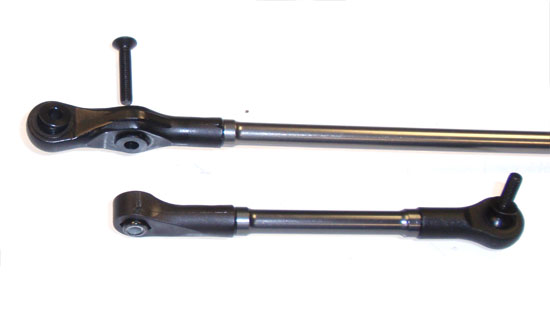
Press a black locknut into the upper steering link and attach to the lower steering link.
Step 29
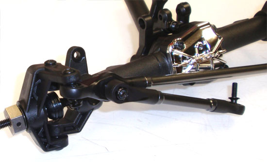
Attach the steering link assembly to the right-side steering knuckle…
Step 30
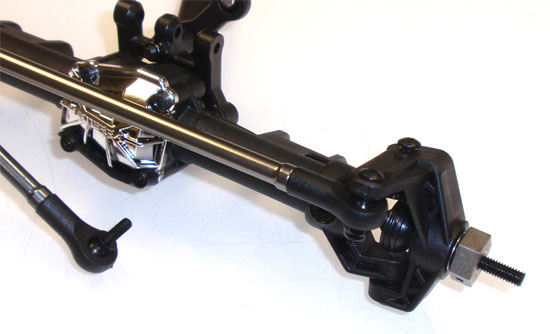
…and the attach the steering link to the left-side steering knuckle. Rotate the steering back and forth a few times to make sure it moves smoothly.
There you have it. Front axle complete!
Vaterra Ascender K5 Blazer Online Build – Part 3
Part 3 of the Vaterra Ascender K5 build involves assembling the rear axle. This process is very similar to the front axle with just a lot less parts. You should be able to breeze through it.
Build Notes:
• None.
Step 1
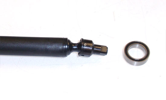
Start off by assembling the center driveshaft. This step is exactly the same as the front center axle you built it Part 2.
Step 2
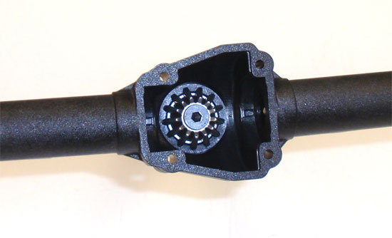
Assemble the rear axle in the same manner as the front. Don’t forget to add a slight dab of threadlocker to the screw securing the sun gear.
Step 3
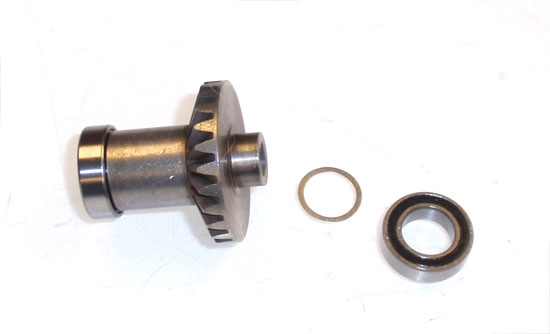
Assemble the rear spool as you did the front. Don’t forget to install the shims prior to the bearings.
Step 4
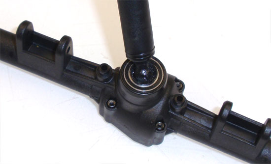
Insert the rear driveshaft assembly into the rear axle housing. You should also press the locknuts into housing at this point as well.
Step 5
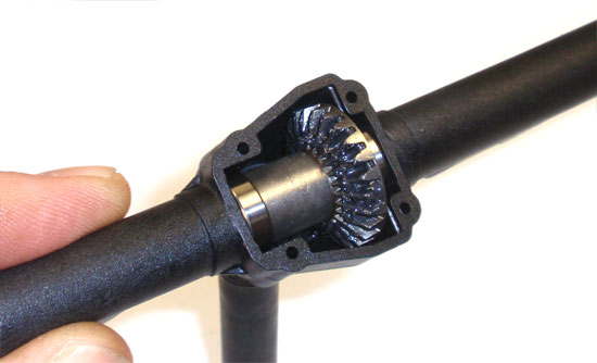
Drop the spool into the rear housing as shown. Add a liberal amount of black grease to the gear and rotate to spread it out.
Step 6
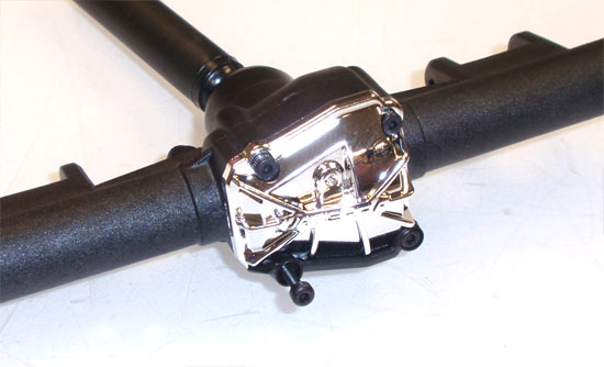
Attach the chrome pumpkin cover (and lower brace) to the rear axle. Remember, the shorter screws go up top; the longer ones down low.
Step 7
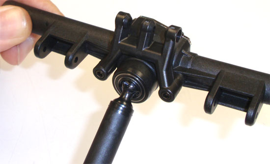
Attach the multi-link brace to the rear axle.
Step 8
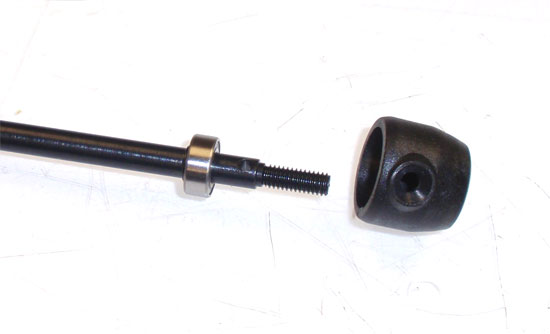
I found it easier to assemble the rear axle prior to sliding it into the axle housing. We’ll use the same method to assemble we did on the rear as we did on the front. Start by sliding a bearing onto the shaft followed by the axle housing cap.
Step 9
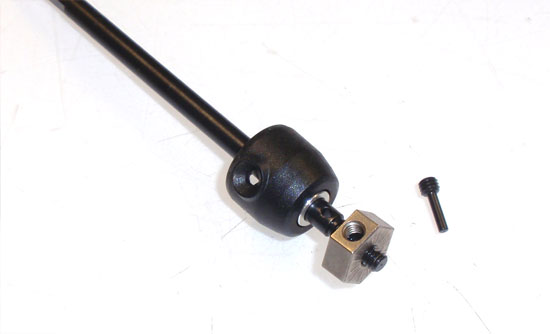
Slide a 2nd bearing on the axle followed by the wheel hex and through-pin. Build 2 of these.
Step 10
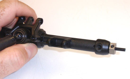
Now slide the axle into the housing. Like the front, we need to apply a small amount of pressure to get the axle as far in the housing as possible. Twist the center driveshaft until you feel the axle key into the spool.
Step 11
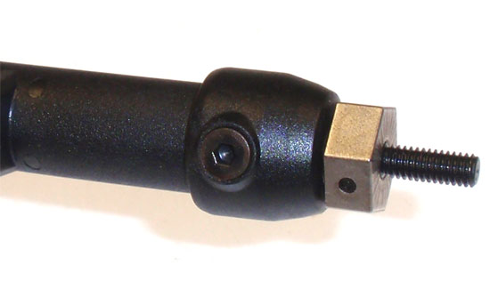
Finally, use the 2 3x6mm screws to secure the axle cap to the housing. Do this for both sides.
Rear axle done!
Vaterra Ascender K5 Blazer Online Build – Part 4
The chassis on the Ascender K5 is very similar in design to other scalers, however Vaterra has added a bit of a twist. Instead of 2 frame rails, they’ve included 4; 2 per side. Depending on the way you assemble them allows you to build it in one of four different wheelbase lengths; 278mm, 290mm, 302mm or 314mm. The assembly process is a little more complicated than a standard crawler so pay special attention to the notes to make sure you build it correctly the first time.
Build Notes:
• Since we’ll be building the Ascender with the K5 Blazer body, we will be using the 314mm wheelbase. That in mind, all of the build steps will be made using the 314mm length. Take a quick look at the frame build on Page 41 of the manual to see how you’ll be building it.
• My center transmission mount side tabs were a bit oversized and wouldn’t fit into the frame rail. I know this is a result to the plastic swelling during production but you might just want to pre-fit yours first to save yourself any headaches later in the build.
Step 1
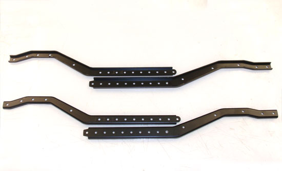
We start off by setting the left and right frame rails together. You’ll notice markings on the outside of the rails; these correspond to the length you plan on building. Again, double check the frame build on Page 41 to see how you need to assemble.
Step 2
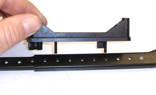
The frame build is a little tricky with only 2 hands so we’ll need to use some ingenuity to complete it. Slide the frame rails together to your desired length. Grab a side rail mount (in this case, the left one, or the one with the wire clip to the back) and slide two screws through the inner-most holes as shown. Now, slide the side rail mount assembly through the frame rails.
Step 3
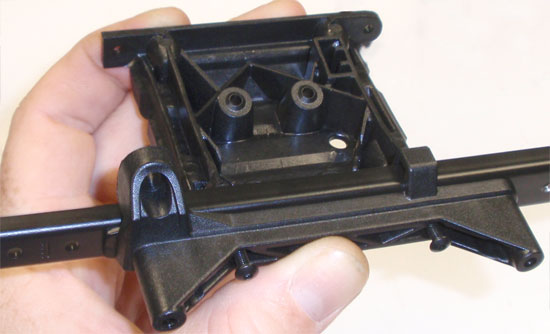
Pick up the left side frame assembly (now sort of held together by the screws) and slide the transmission mount into place. Screw the two screws from Step 73 into the mount. Note the orientation of the mount.
Step 4
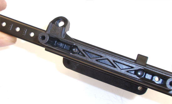
This is a side view of the left side rail mounted to the center transmission mount. At this point you can install the 3rd screw in the front-most hole, securing on the backside with a black locknut.
Step 5
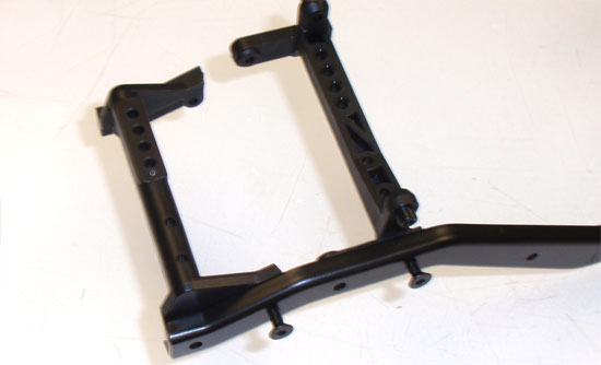
The instructions have you ‘slide’ these mounts into place and, for the most part, they do stay in place. However, you have to be careful not to knock the parts out of position and, during final assmbly, line up the mounting holes. I decided to use some screws to keep the mounts keyed into position from here on out. You only have to tighten the screws just a tad; enough to get them to hold the parts in place.
Step 6
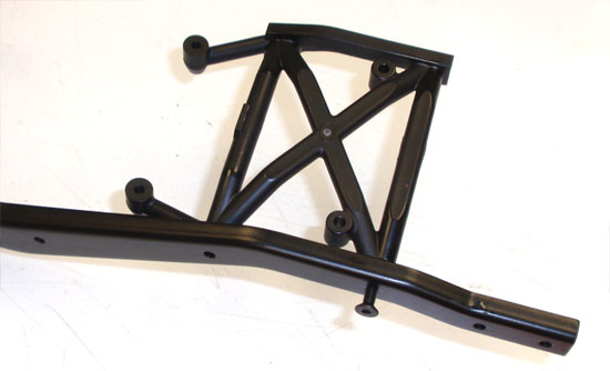
Attach the rear electronics box mount the same way.
Step 7
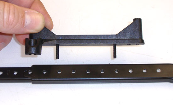
Slide the right-side chassis plates together as you did in Step 73. Slide two M3x16mm screws through the inner holes of the right-side side rail mount and insert them into the corresponding holes (dependent on your chassis length) as you did in Step 73.
Step 8
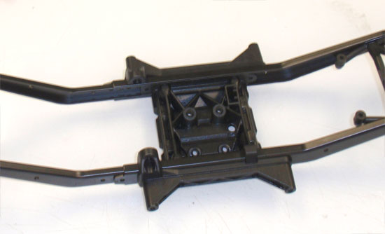
Pick up your right-side frame assembly and, using the same method we did in Step 74, attach the frame to the center transmission mount. This is a good time to double-check your frame length to make sure it is correct.
Step 9
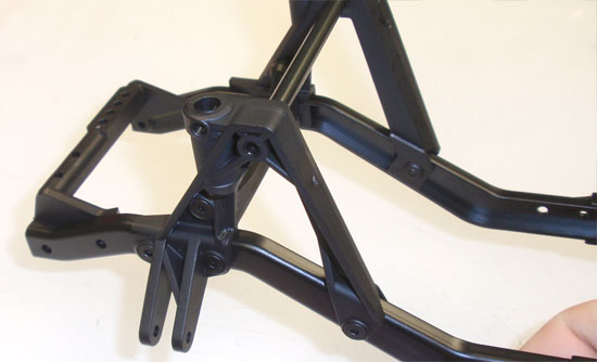
The next step is to attach the front shock hoops. First, remove the screws you used to hold the center mounts into place (if you used them). If you noticed that the hoops look different than what is shown in the manual, you have a keen eye. First, make sure you have the two FRONT hoops; they’ll fit the front mounting points but may have the body mount locators to the front (instead of to the back as the manual shows). You’ll also notice that the right front one has the panhard rod mounting tab. Attach both of these to the front, using the plastic ‘chassis nuts’ to lock the mounts into place. Now slide the aluminum tube in-between the two mounts as shown.
Step 10
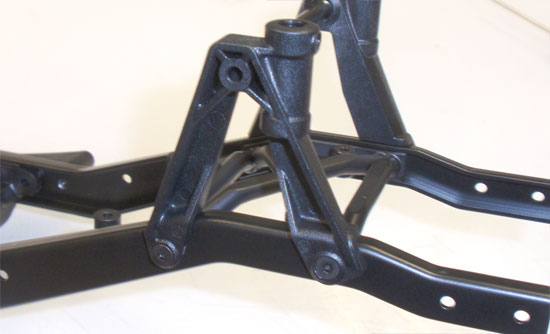
Remove the screws you used to hold the rear center mount into place (if you used them) and then follow the same procedure in Step 80 to attach the rear shock hoops on the rear.
Step 11
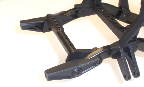
Remove the screws you used to hold the center-front mount into place (if you used it) and attach the front bumper extenders into place.
Step 12
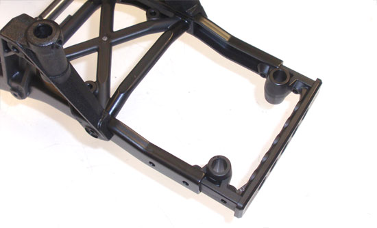
Slide the rear chassis support in-between the frame rails as far as it will go.
Step 13
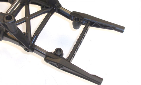
Attach the rear bumper extenders as shown.
Step 14
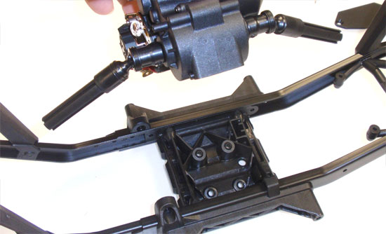
Because the mounting holes in the transmission were pretty tight, I pre-drilled them to make this part of the build much easier. I would suggest doing that prior to installation. Once you place the transmission assembly into position…
Step 15
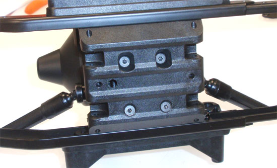
…attach the 4 screws into the bottom of the transmission to hold it in place. Tighten all the way down.
Awesome job! One step closer to completion!
Vaterra Ascender K5 Blazer Online Build – Part 5
The manual has us assembling the chassis and installing the electronics in the same step but I chose to break it out into two for simplicity sake. Vaterra has given us a few cool features in the electronics install section and I felt it needed its own section.
Build Notes:
• As with all builds, it’s a good idea to make sure all your electronics are working and your servo is centered prior to installing. So, take a moment, hook it up and test it.
• Depending on which wheelbase option you’ve chosen, there are two ways to mount the servo. Wheelbase options WB3 and WB4 use the method we’re explaining here; wheelbase options WB1 and WB2 will use the build option on Page 46 of the manual.
Step 1
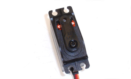
The first step in the electronics build is to prep the servo for install. Attach the servo horn as shown after, of course, you did the electronics pre-test. It should be lined up straight down the servo.
Step 2
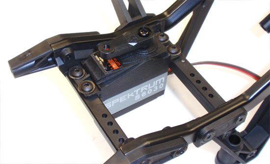
Flip the chassis over and mount the servo using the M3x10mm screws. Don’t forget the washers. Also, note the orientation and direction of the servo.
Step 3
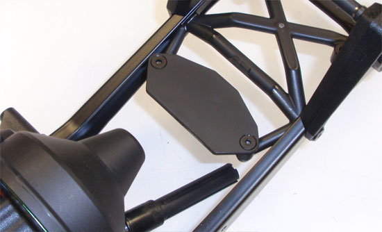
Attach the ESC mounting plate to the extensions off the back brace.
Step 4
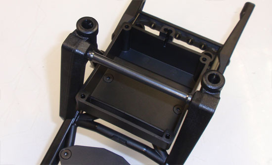
Attach the receiver box. It’s not waterproof but it doesn’t look like it would be that hard to waterproof it yourself. Make sure the antenna tube mount is to the rear.
Step 5
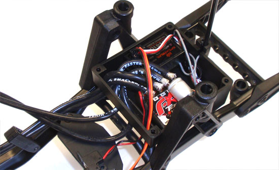
There’s quite a bit of room in the box, enough for a small receiver and a lighting control module. Since my Tekin ESC isn’t waterproof, I elected to drop it in here for a little extra protection. You’ll need to do some creative wiring to make everything fit but it’s possible. I would suggest measuring out the wires prior to soldering to the ESC to make sure they are long enough.
Step 6
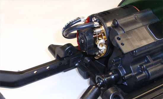
Solder up the wires to the motor. You can run them through the wire looms on the right side of the chassis to keep things neat.
Step 7
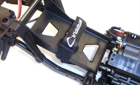
The manual has you installing the floating battery tray in the next step but I chose to do it now so that I could make sure my wiring was out of the way. Feed the strap through the tray and attach the tray to the rotating points.
Step 8
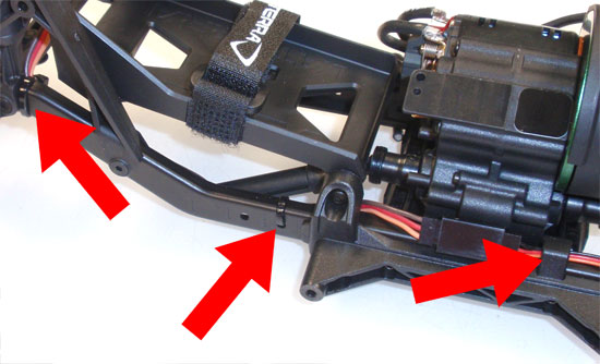
One problem with the Ascender is the fact that the servo lead will not reach the receiver box; the distance is to great. You will need to get a servo extension of at least 9″. Once again,you can feed the lead through the looms but they are only located near the back of the chassis. To keep them from getting hung up on any rocks (or chassis bits), I zip-tied them to the chassis. You can see my locations in the picture (check out the groovy red arrows).
Step 9
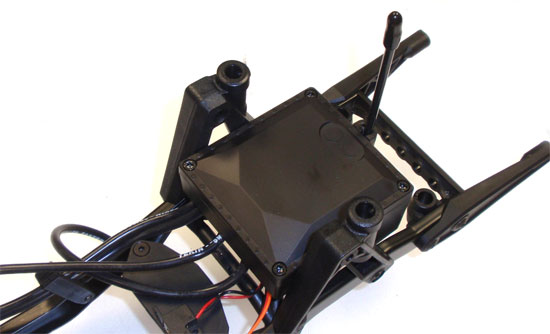
Once you get the electronics figured out, all the leads up through the radio box opening and the antenna mounted, attach the radio box cover. I mounted the switch on the ESC tray.
Now that your electronics are installed, you can insert your battery and do the final battery wiring. I used the same plug that came on my Dynamite battery.
x
Vaterra Ascender K5 Blazer Online Build – Part 6
Part 6 of our Ascender K5 build has us assembling the shocks. Vaterra was nice enough to give us some good, threaded shocks that are easy to build and work great. On to the build.
Build Notes:
• The shocks go together very easily, however I think the oil supplied is a bit thick (or the holes in the piston are too small). The truck handled good but I think a little lighter oil might be the way to go.
• I would suggest picking up a pair of shock-building pliers. These pliers grab the shaft while preventing any mars or knicks on it, possibly causing the shaft to rip the internal o-rings. I’ve listed a few at the end of the article if you’re interested in picking some up.
Step 1
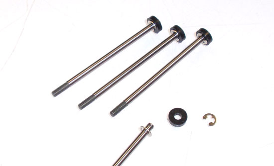
Let’s start by assembling the shock shafts and pistons. Build 4 as shown, starting with the lower e-clip, the piston and then the upper e-clip.
Step 2
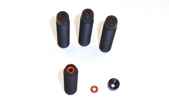
Press both o-rings into the bottom of the shock. Apply 1 or 2 drops of oil to the center of the o-rings; it will drip down and coat the inner area of both. Capture both with the lower cap. Build 4 of these.
Step 3
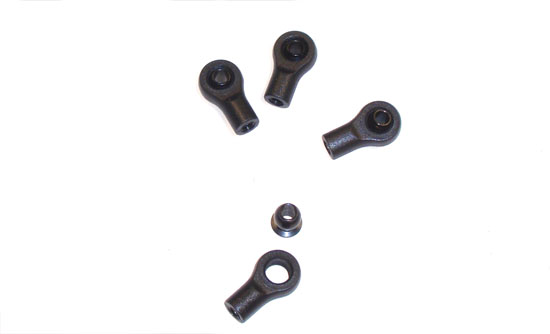
Pop the ball into each shock rod end. Build 4 of these.
Step 4
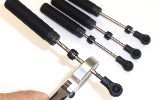
Put a drop of shock oil onto the threads of the shaft and SLOWLY slide it through the shock body. You want to make sure the threaded part of the shaft doesn’t catch on the o-rings and rip them. Once through, slide the bump spacer onto the shaft and screw on the rod end. Here is where a pair of shock-building pliers come in handy. You don’t want to scratch the shaft or it could rip the o-rings.
Step 5
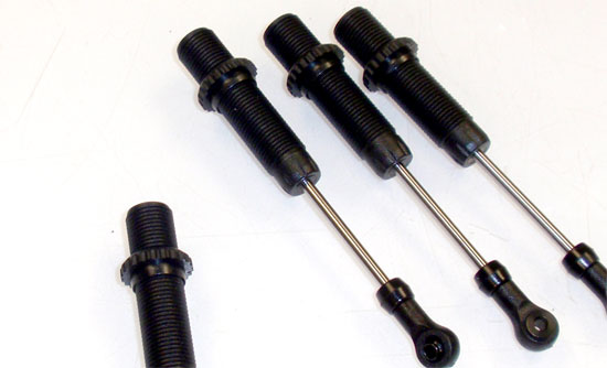
Thread the pre-load retainer onto the shock. We will use this to hold the shocks in our shock station while the bubbles rise out of the oil.
Step 6
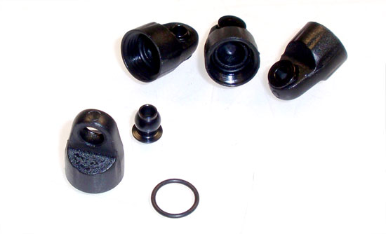
We want to also assemble our caps now as well. Pop the balls into the caps, then seat the o-ring into the grooves inside the caps. Make sure the o-ring is all the way down inside so it doesn’t get pinched.
Step 7
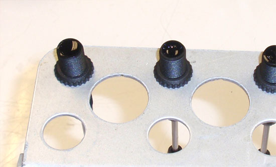
Fill the shocks with oil all the way to the top. SLOWLY slide the shock shaft up, allowing the air under the piston to escape. This will also lower the level of the oil, so refill to the top; flat with the top of the body is fine. Set aside all the air bubbles can escape the shock; typically only a few minutes.
Step 8
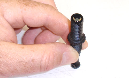
To bleed these shocks, I found the easiest way was to hold the shock against your workspace and SLOWLY compress it. Oil will spill out of the top as the piston rises up, so make sure you have a few paper towels down first.
Step 9
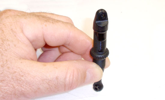
Once it is fully compressed, screw the cap on. A little more oil might escape, but that’s ok. Tighten the cap down and then wipe the excess oil off the shock. Build 4 of these.
Step 10
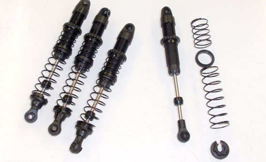
Install the short spring followed by the mid-spring retainer, the longer spring and then the lower spring retainer. You may need to adjust your pre-load retainers up a bit, but just make sure they are all the same.
There you have it; 4 expertly built shocks ready to install!
Vaterra Ascender K5 Blazer Online Build – Part 7
Next up on our Vaterra Ascender K5 Blazer build are the suspension links. We’ll be building 2 pair for both the front and the back as well as the panhard rod.
Build Notes:
• The manual does have build steps for each length of links depending on which wheelbase you’re going to use. Step 106 (the first step) gives you a little tip on how to make sure you build the right link lengths.
• The links are aluminum so make sure you use a bit of threadlocker on the long setscrews to ensure they don’t come apart.
Step 1
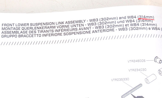
To keep things straight when building, I suggest underlining the wheelbase option at the top of the manual for the lengths you are going to build. Do this on all the pages with 314mm (for this example); it will help alot.
Step 2
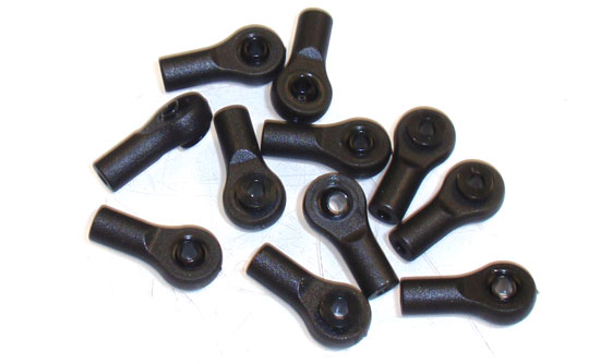
I like to do a little pre-prep work prior to building. Start by pressing the flanged balls into the rod ends as shown.
Step 3
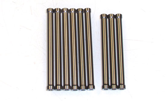
You’ll notice there are two lengths of rods; 61mm and 66mm. Separate them off to the side for quick reference.
Step 4
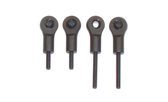
Front Lower Suspension Links – Take 4 of your pre-prepped rod ends and screw the setscrews (2 short, 2 long) in as shown.
Step 5
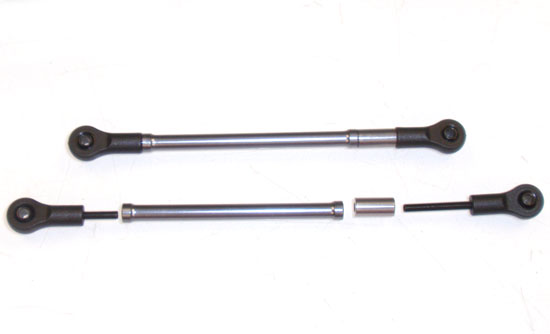
Dab a bit of threadlocker onto the setscrews and assemble 2 links. Make sure you add one of the 12mm spacer to the side with the long setscrew. Also make sure the flanges sides of the balls are facing the same way. Set these aside.
Step 6
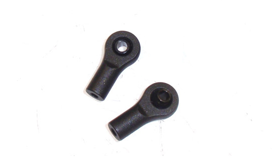
Front Upper Suspension Link – Take 2 more rod ends and press 2 UN-flanged balls into them. Keep these separate from the flanged rod end assemblies.
Step 7
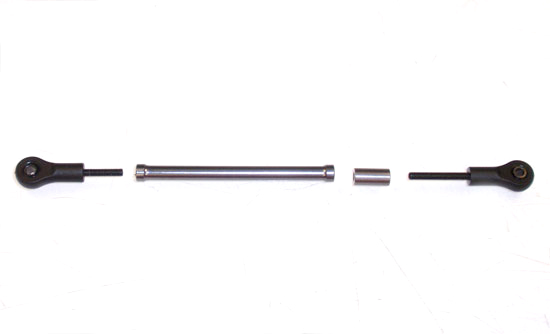
Build the upper link as shown using 1 UN-flanged rod end assembly with the short setscrew and 1 flanged rod end assembly with the long setscrew. There is a catch, however. You’ll need to use one of the 61mm links instead of the 66mm one the manual suggests. This is an oversight from the factory and might be fixed in you manual. Also, don’t forget the dab of threadlocker on the setscrews. Set this aside next to the upper link you just built.
Step 8
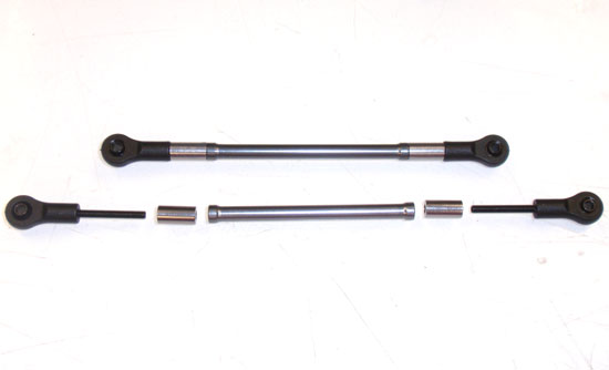
Rear Lower Suspension Links – Assemble 4 more rod end assemblies, all of these with the flanged rod end assemblies and the longer setscrews. Dip the setscrews into threadlocker and build 2 link assemblies as shown. Set these aside next to your other assembled links (don’t get them mixed up!)
Step 9
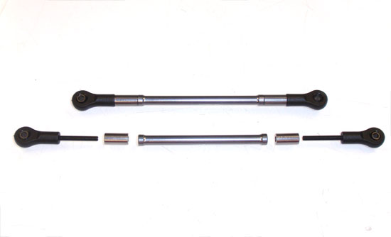
Rear Upper Suspension Links – Build the rear upper suspension links using two UN-flanged rod end assemblies and two flanged rod end assemblies. Both of these require the longer setscrews and the 12mm spacers. Don’t forget your threadlocker.
Step 10
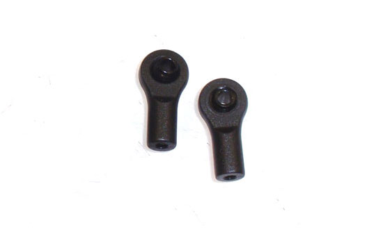
Panhard Rod Link – The original manual does not include the steps required to build the panhard rod, but future versions might. For now, let’s just build two rod end assemblies; one flanged, one un-flanged.
Step 11
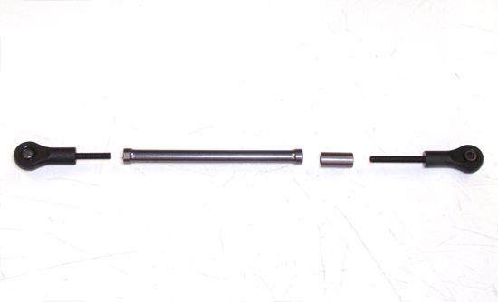
Assemble the panhard rod as shown using a 66mm link. Make sure the un-flanged rod end gets a long setscrew and the flanged rod end gets a short setscrew. Don’t forget your threadlocker and 12mm spacer.
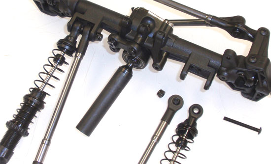
Step 12
Grab a pair of shocks and your two front lower links from Step 109 and attach them to the front axle as shown. Do not overtighten the screw; just get it snug in the nylon nut. You also want to make sure the flanged balls are facing AWAY from each other.
Step 13
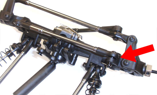
Attach the flanged rod end side of the panhard rod (from Step 115) to the tab on the steering block (see groovy red arrow).
Step 14
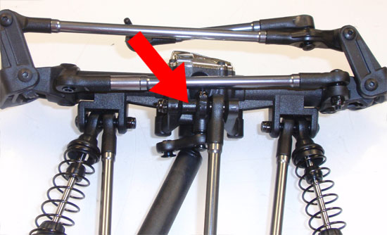
Now, attach the single, front upper suspension link (from Step 111) to the top of the front axle. Use the metal spacer to fill the gap on where the screw goes through (sounds complicated, much easier when you see it … see arrow).
Step 15
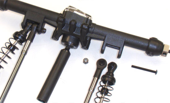
Moving to the rear, we’ll attach the last two shocks and rear lower suspension links (from Step 113) as shown. Again, make sure the flanged side of the balls are facing AWAY from each other. Do not overtighten.
Step 16
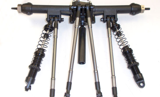
Finally, attach the rear upper suspension links (from Step 114) to the top of the rear axle.
Whew. Lots of links, lots of careful building. Congrats.
Vaterra Ascender K5 Blazer Online Build – Part 8
Now that we’ve put the links on the axles, we need to attach the axles to the chassis. This appeared like it might be a little crazy with all the links and shocks spidering all over, but actually wasn’t that big of a deal once I found the ‘process’. So, on we go to Part 8; attaching the links to the chassis.
Build Notes:
• None. This step is pretty simple to follow.
Step 1
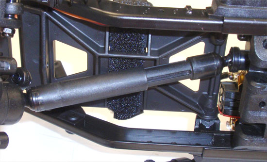
We’ll start this step by attaching the front axle/links assembly to the chassis. First, assemble the slider at the front of the transmission to the slider on the front axle.
Step 2
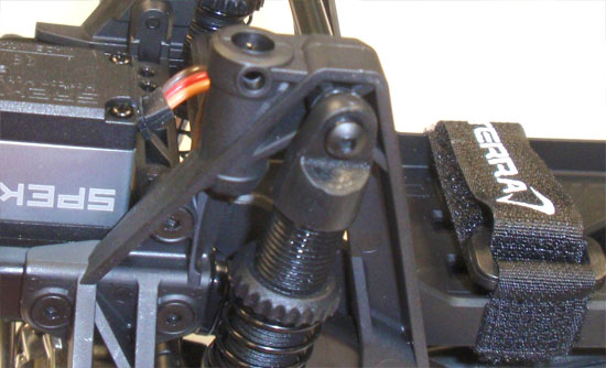
Attach both shocks to the tower. You’ll want to apply a dab of threadlocker since the screws go into the aluminum support tube. Make sure the slider shaft stays connected.
Step 3
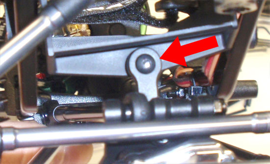
Now that we’ve attached the shocks, the axle/links assembly should stay connected to the chassis without us having to manipulate it to stay. The next step is to attach the small, front axle link to the floating battery tray. Sorry for the slighly blurry pic.
Step 4
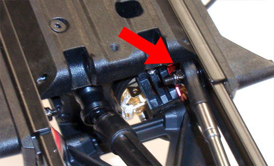
Now attach the single, upper front link to the chassis as shown with the red arrow. You will be capturing the screw with a black locknut.Do not overtighten.
Step 5
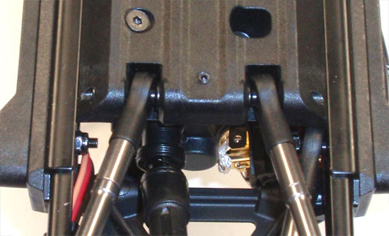
Slide the two lower, front links into position and feed the long, chrome retainer pin into place through the holes in the center transmission plate. Secure the pin with the setscrew.
Step 6
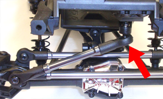
Swivel the servo horn and press a black locknut in the back of it. Now attach the steering link to the servo horn as shown with the red arrow.
Step 7
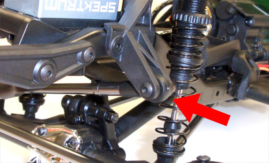
Finally, connect the panhard rod to the panhard rod mount. Do not overtighten. Your front suspension has been installed.
Step 8
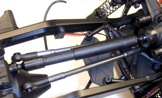
Attaching the rear axle/links assembly is very similar to the front. Start by sliding the rear center driveshaft together.
Step 9
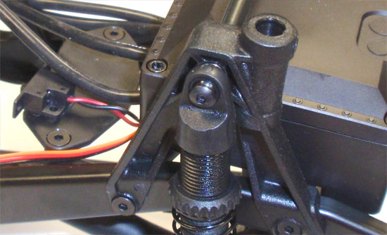
Attach both shocks to the towers. Again, don’t forget a dab of threadlocker to keep the screws from backing out.
Step 10
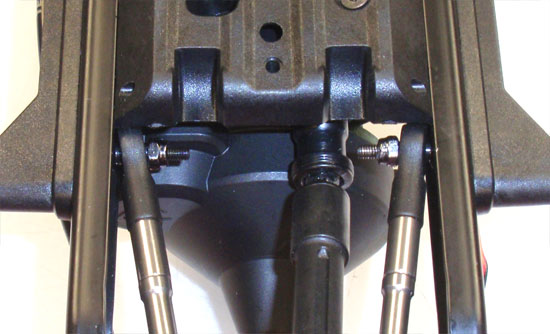
Attach the two upper suspension links to the chassis as shown. Secure with the black locknut.
Step 11
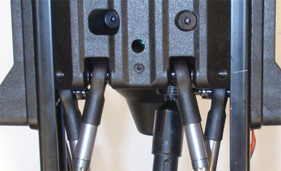
Finally, slide the two lower suspension links into place. Slide the chrome retaining pin into place to capture the rod ends. Use the M3x5mm setscrew to hold the retaining pin.
There you have it! Front and rear axle/links in place. Pretty easy install with very little hassle!
Vaterra Ascender K5 Blazer Online Build – Part 9
The final step to our Vaterra Ascender K5 build has us attaching the front and rear bumpers, side bars and wheel/tire assemblies. We’ll also be installing the body mounts however I won’t be showing you how to do the body, just in case you’ve decided not to use the bad ass K5 shell.
Build Notes:
• As I mentioned before, I won’t be showing the body install here. If you aren’t using the K5, you’ll need to adjust the body mounts to fit whatever body you’re using.
• You’ll be using CA glue to mount the tires to the wheels. CA glue is some nasty stuff and glues things together very quickly … even fingers. Be especially careful during the tire gluing step. No one likes to glue their fingers to the tires.
Step 1
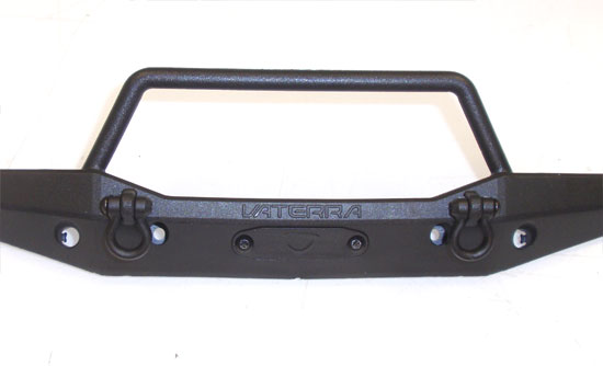
Start by attaching the two tow hooks and winch cover to the front bumper.
Step 2
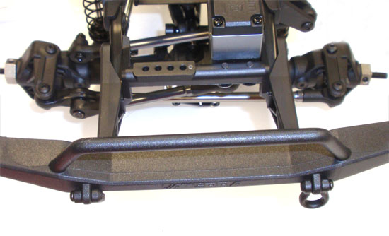
Attach the front bumper to the bumper mounts on the chassis. Don’t forget to use the plastic spacers. These extend the bumper out far enough to clear the K5 body.
Step 3
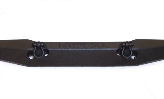
Attach the tow hooks to the rear bumper.
Step 4
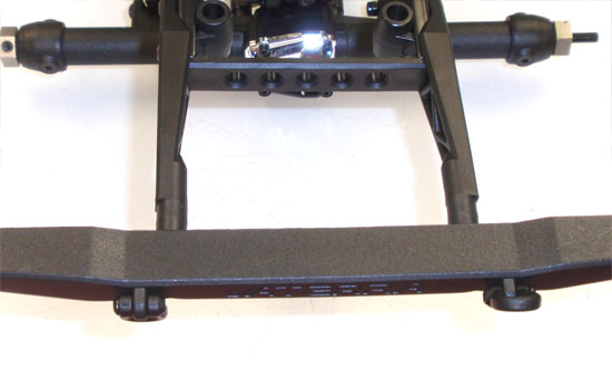
Now attach the rear bumper to the chassis. You’ll be using 2 plastic spacers per side to extend the bumper out.
Step 5
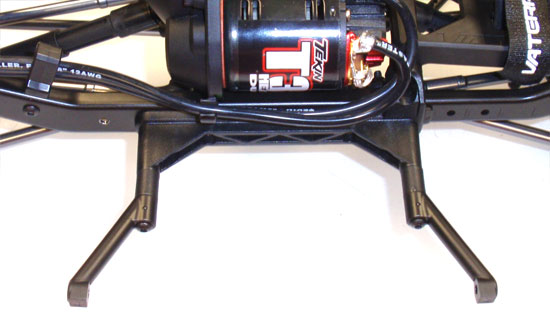
Attach two of the side bar extenders to the mounts on the chassis. The mounts should be angled up just slightly.
Step 6
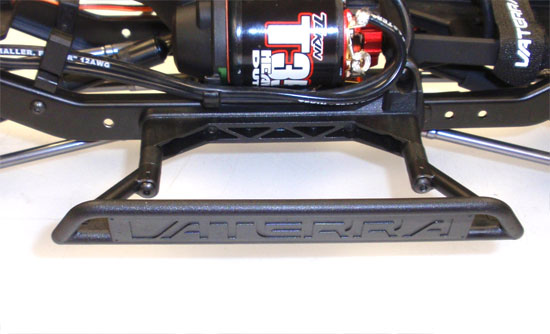
Mount the side bar to the extenders. You may need to adjust the extenders slightly fit the side bar. Do this on both sides.
Step 7
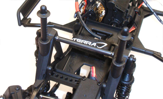
We’re skipping ahead slightly to the body mounts since we’re still working on the chassis. Slide the front body mounts into place. Don’t worry about the height of these; you’ll probably need to adjust them during the final body install.
Step 8
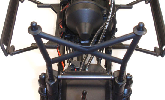
Attach the rear body mount. Again, you’ll probably need to adjust this during final body install but go ahead and make sure, at this point, that both the left and right are in the same mounting hole.
Step 9
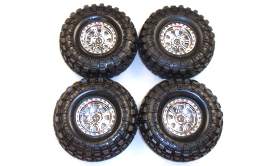
Stuff the foam inside the tires (if it’s not already in there) and then wrap the tires around the wheels. Using a very fine tip on your glue bottle (I ALWAYS use the CompetitionX Gloo Toobs), run a bead of glue around the tires. Wait for about 10-15 minutes (to make 100% sure it’s dry), then flip the tire assembly over and do the same to the backside.
Now attach the tire assemblies to the axles, lower the body into place and get out on those rocks!
Thanks for following along with the Vaterra Ascender K5 build.

