

HPI Savage XS SS Online Build

If you familiar with HPI’s Savage XS, you know that this is one mean mini machine! Packed with HPI’s potent Flux system, this little rocket can hit speeds of up to 65mph on a 3S pack.
To make the Savage XS better (at least in my eyes), HPI now offers it as an SS kit-build. That means you get the enjoyment of building it and stuffing it full of whatever power system you want!
Follow our step-by-step build up right here on CompetitionX. Testing and my final thoughts will be posted in an upcoming review.
HPI Savage XS SS Online Build – Part 1
We will be starting off the Savage XS SS build like we start off most vehicles; with the differentials. While this Savage may be ‘Mini’, the parts are still a good size so there’s no need to worry if you have big ol’ sausage fingers.
Build Notes:
• Since we’ll be working with the differential, you’ll obviously be dealing with differential oil. Make sure your area is nice and clean and have plenty of rags handy for clean-up.
• Small Phillips screws hold the differential together. The fit of the screws into the plastic diff half is pretty tight so make sure you have a good, quality Phillips screwdriver or you risk stripping them out.
Step 1

The first thing we’ll want to do is take the parts shown and move them to the side. These are for the next step (Front Gearbox). Note the input and gear; the longer shaft and taller gear are the ones you’ll set aside.
Step 2

Take the diff outdrive and slide it into the gear as shown.
Step 3

Place the black o-ring and shim over the outdrive shaft and slide the pin through the hole. In this picture the o-ring is already installed. Make sure it seats all the way down into the notch.
Step 4

Place the green gasket onto the gear face as shown. Make sure you line the holes up. If the gasket does not stay, a dab of black grease will keep it in place. Align the notch in the back of the sun gear with the pin on the shaft and press into place. Again, if it does not stay, a dab of grease will help.
Step 5

Slide the 2nd diff outdrive into the diff housing.
Step 6

As we did with the diff gear, slide the o-ring and shim into place.
Step 7

Make sure the o-ring seats all the way down into the notch.
Step 8

Take a thin tool (one of the ones HPI supplies will work) and slide it into the hole in the diff housing. You will want to rotate the diff outdrive until the hole lines up with the tool…
Step 9

…then slide the pin through the hole in the housing and into the hole in the outdrive. It is possible to do insert it by dropping the pin in from the top but this was was much easier. Align the notch in the back of the sun gear with the pin and drop into place.
Step 10

Insert the set screw into the diff housing and tighten it down until it is flush. Rotate the outdrive to verify that you have not tightened it too much…you do not want the set screw to hit the sun gear.
Step 11

Gather the parts shown and build two satellite gear assemblies. Note the location of the shims and the direction of the gears.
Step 12

Slide one of the satellite assemblies into place as shown. Make sure the flat spot on the shaft is pointing up.
Step 13

Slide the second satellite gear assembly into place as shown, making sure the flat spot on the shaft is pointing down. You want the flats spots to be resting against each other.
Step 14

Fill the differential about 95% up with diff fluid. I used 7000wt fluid. Rotate the diff outdrive to help circulate the fluid through the entire housing. Re-fill if you need to.
Step 15

Now take your diff gear assembly and turn it over onto the diff housing assembly. You want to make sure the screw holes are aligned; neither the gear nor housing are keyed to make this easier. Just take your time here.
Step 16

Using the dainty Phillips screws, secure the two assemblies together. This is where your quality Phillips screwdriver is almost a necessity.
Step 17

Slide one shim and one bearing over the outdrive. Make sure it drops all the way to the face of the gear.
Step 18

Add two shims and a bearing to the housing side of the diff. Make sure they seat all the way against the housing. Mine didn’t so I had to do a little sanding of the housing ‘nub’.
HPI Savage XS SS Online Build – Part 2
In Part 2 of the HPI Savage XS SS build we will be tackling the Front Gearbox. This is a pretty easy step and shouldn’t take long at all.
Build Notes:
• In a few of the steps you will be pressing a locknut into a plastic ‘space’. To make this easier, align the locknut so the flat sides match the flat spots in the ‘space’.
Step 1

This is a pretty simple step; press the bearings into the bearing support. Done.
Step 2

Take the bearing support, align it and secure with the two 3x35mm screws. The locknuts help secure the screws. Note the direction of the bearing support. I didn’t check it but I’m pretty sure it only goes in one direction (correctly).
Step 3

Find the longer outdrive and taller sun gear from the differential step. Slide the outdrive into place, insert the pin and press the sun gear over the pin. If you turn it over the sun gear might fall out. Put a dab of grease on the pin area and that should keep the gear in place.
Step 4

Take you built diff, liberally coat the gears with the supplied grease…
Step 5

…and drop it into the gearbox. Note the direction of the diff. Also make sure that the bearings sit INSIDE the small lip. If it doesn’t fit, the bearings are not on all the way. Fix this before you move on.
Step 6

Attach the upper gearbox half into place. Press the locknut into the groove on the gearbox. As mentioned, lining up the flat spots will make this much easier. Do this on both sides.
Step 7

Secure the two halves with the 3x35mm screws.
Step 8

Insert a pair of locknuts in the rear of the front upper gearbox half. Now set the front shock tower into place and secure with the 4 screws. Make sure the 3x18mm screws are on top.
Step 9

Press the lower gearbox mount into place. This piece is a little tricky so I had to trim off a little bit of plastic to make it fit.
HPI Savage XS SS Online Build – Part 3
Tackling the front (and rear) suspensions are a little more involved that most of the other steps with this build. HPI has made it quite easy though and you should not have any problems.
Build Notes:
• Pay close attention to the hinge pins and the camber pins. The hinge pins are the thicker pins and you will use them in Step 35. The camber pins are thinner and you will use them in Step 42.
• You will be building a left and right side of the suspension, however I will only be showing one side of the build.
Step 1

We start off the build with the CVDs. Put a bit of black grease on the cross joint and push it through the axle as shown. A set screw threads into the cross joint, but only from one direction (or the open end). Make sure you insert the cross joint with the ‘closed end’ first. This will avoid getting any grease on the threads.
Step 2

Apply a liberal amount of black grease on the axle ‘ball’ and insert it into the axle. Take your cross pin and insert it as shown. Make sure to line up the flat spot with the ‘open end’ of the cross joint.
Step 3

Apply a dab of threadlock onto the set screw and insert it as shown. Make sure the set screw contacts the flat spot of the cross pin. Build two of these.
Step 4

Grab one of the steering blocks and insert a ball end and locknut as shown. We will be building two of these so do the same thing for the opposite side (you will need to build it as an opposite side, also).
Step 5

Press the bearings into place, one on each side of the steering block.
Step 6

Take one of your assembled CVDs and slide it through the bearings. Insert the axle through the caster block and press the block into place. Note the orientation of the block.
Step 7

There are two types of pins provided: the hinge pins and camber pins. Separate and set the camber pins aside.
Step 8

Insert a hinge pin in both the top and bottom holes on the steering block as shown. These should feed into the caster block, locking both parts together.
Step 9

Use a 2.5x4mm to secure the hinge pins in place. Insert one on both the top and bottom.
Step 10

Take one of the suspension arms and attach the assembled steering block into place. Note the direction of the suspension arm.
Step 11

Attach an arm brace to both the rear of the assembled gearbox…
Step 12

…and the front. They are both the same so don’t worry about getting them mixed up. Now slide the suspension arm assembly between the arm mounts and feed the long hinge pin through. Yes, it might be a bit tight, but as long as the completed assembly swings freely you’re ok.
Step 13

Assemble the camber links per the instructions.
Step 14

Add a bit of black grease to the ball of the CVD…
Step 15

…and feed it into the diff outdrive. Take one of the camber links and slide it into position on the shock tower. Use one of your thinner camber pins to lock the camber link into place…
Step 16

…followed by a 2.5x4mm screw. This screw keeps the camber pin in place.
Step 17

Swing the camber link into place and secure in the caster block.
Step 18

Press a pair of locknuts into the top of the gearbox case. Make sure they are seated all the way down. Take the front bumper brace and feed it into the two holes in the shock tower.
Step 19

Secure with the pair of plastic c-clips.
Step 20

Attach the plastic mount to the metal skid-plate brace.
Step 21

Attach the metal skid-place brace to the bottom of the gearbox. The plastic mount (you attached in Step 47) should be towards the rear of the gearbox.
Step 22
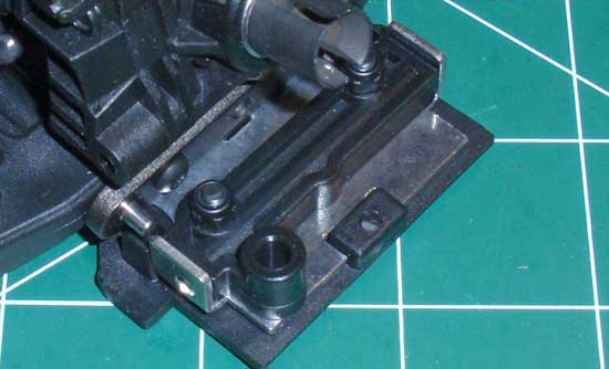
Locate the ‘box’ on the plastic skid plate. Insert the tab on the rear of the metal skid-plate into the box as shown…
Step 23

…and press the gearbox down and into place. The hinge pins should drop into the grooves in the plastic skid plate. You may need to slide the pins slightly forward or back to make them fit.
Step 24

Secure the plastic skid plate to the gearbox with the 4 screws.
Step 25

Swing the bumper brace into place and secure with the 3x18mm screws.
Step 26

Press the headlight caps into place and apply the stickers as shown. If you don’t get them perfectly straight, it’s ok. Use a flat head screwdriver and rotate them from behind to straighten them out.
Step 27

Attach the lights to the front bumper as shown.
Step 28

Build a pair of steering links.
Step 29

Pop the steering links into place as shown. Set this assembly aside for now.
HPI Savage XS SS Online Build – Part 4
The build of the rear differential is exactly the same as the front. I would have liked to build both at the same time but because the rear diff parts were 2-bags deep in another location, I opted to just build it per the instructions.
Build Notes:
• Since we’ll be working with the differential, you’ll obviously be dealing with differential oil. Make sure your area is nice and clean and have plenty of rags handy for clean-up.
• As I’m sure you’ve learned from the front diff, a high-quality small Phillips screwdriver is essential in screwing the screws in. Find one.
Step 1
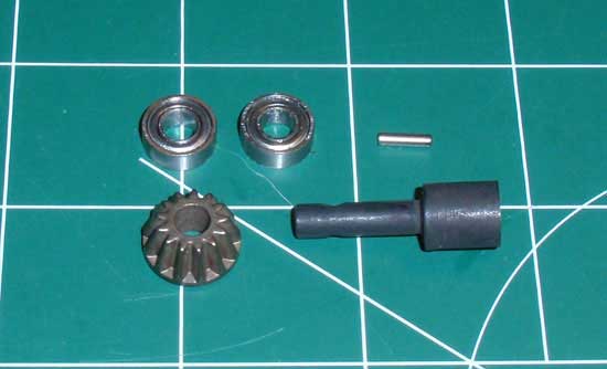
The first thing we’ll want to do is take the parts shown and move them to the side. These are for the next step (Rear Gearbox). Note the input shaft and gear; the longer shaft and taller gear are the ones you’ll set aside.
Step 2
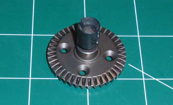
Take the diff outdrive and slide it into the gear as shown.
Step 3
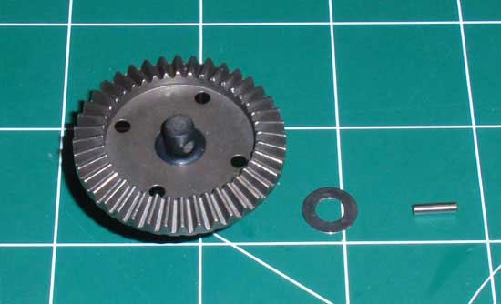
Place the black o-ring and shim over the outdrive shaft and slide the pin through the hole. In this picture the o-ring is already installed. Make sure it seats all the way down into the notch.
Step 4
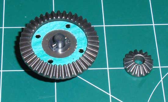
Place the green gasket onto the gear face as shown. Make sure you line the holes up. If the gasket does not stay, a dab of black grease will keep it in place. Align the notch in the back of the sun gear with the pin on the shaft and press into place. Again, if it does not stay, a dab of grease will help.
Step 5
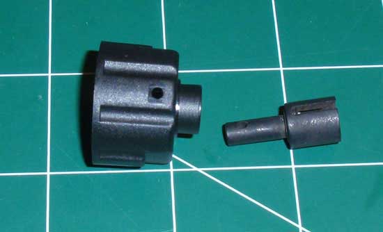
Slide the 2nd diff outdrive into the diff housing.
Step 6
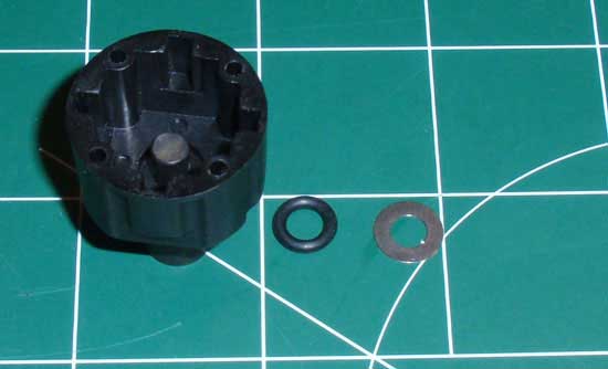
As we did with the diff gear, slide the o-ring and shim into place.
Step 7
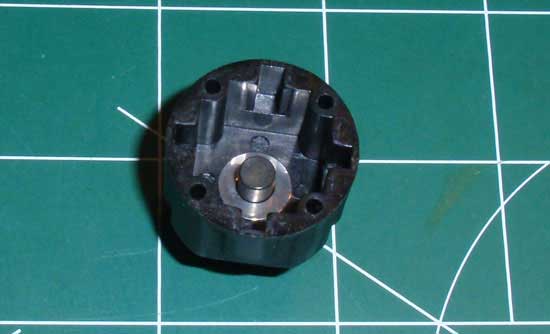
Make sure the o-ring seats all the way down into the notch.
Step 8
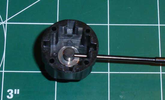
Take a thin tool (one of the ones HPI supplies will work) and slide it into the hole in the diff housing. You will want to rotate the diff outdrive until the hole lines up with the tool…
Step 9
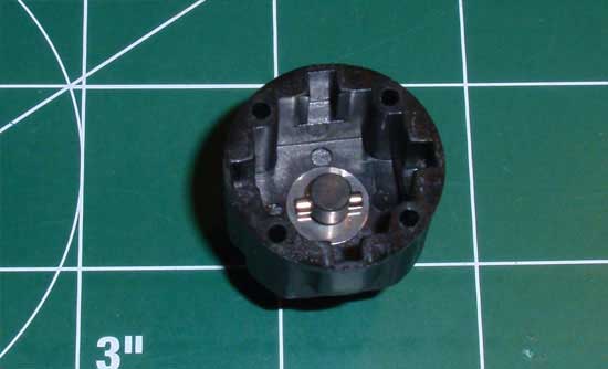
…then slide the pin through the hole in the housing and into the hole in the outdrive. It is possible to do insert it by dropping the pin in from the top but this was was much easier. Align the notch in the back of the sun gear with the pin and drop into place.
Step 10
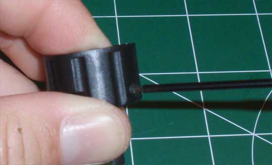
Insert the set screw into the diff housing and tighten it down until it is flush. Rotate the outdrive to verify that you have not tightened it too much…you do not want the set screw to hit the sun gear.
Step 11
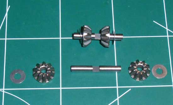
Gather the parts shown and build two satellite gear assemblies. Note the location of the shims and the direction of the gears.
Step 12
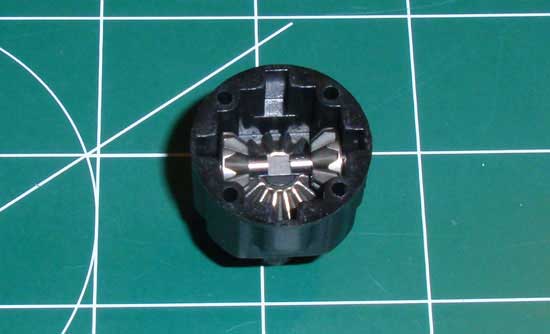
Slide one of the satellite assemblies into place as shown. Make sure the flat spot on the shaft is pointing up.
Step 13
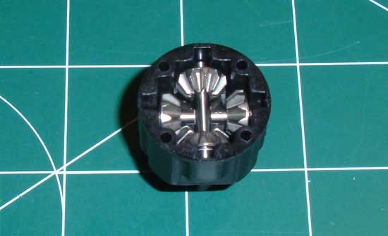
Slide the second satellite gear assembly into place as shown, making sure the flat spot on the shaft is pointing down. You want the flats spots to be resting against each other.
Step 14
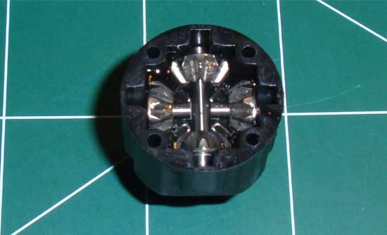
Fill the differential about 95% up with diff fluid. I used 5000wt fluid in the rear. Rotate the diff outdrive to help circulate the fluid through the entire housing. Re-fill if you need to.
Step 15
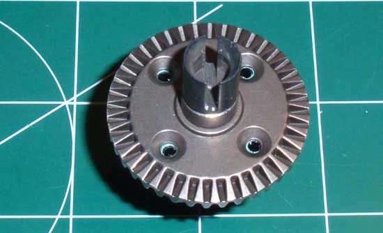
Now take your diff gear assembly and turn it over onto the diff housing assembly. You want to make sure the screw holes are aligned; neither the gear nor housing are keyed to make this easier. Just take your time here.
Step 16
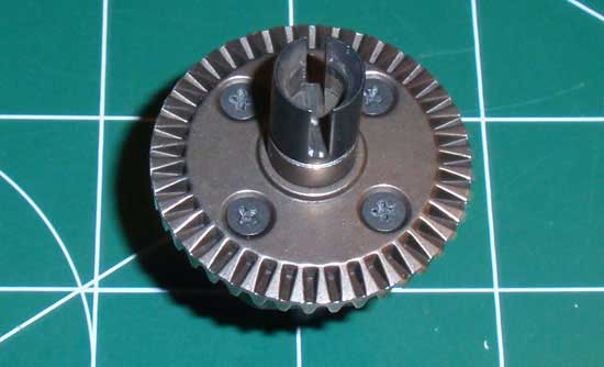
Using the dainty Phillips screws, secure the two assemblies together. This is where your quality Phillips screwdriver is almost a necessity.
Step 17
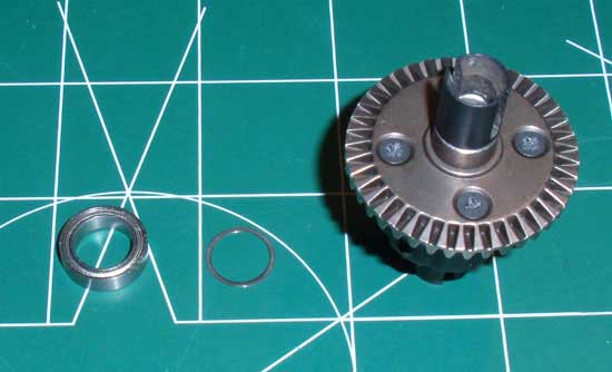
Slide one shim and one bearing over the outdrive. Make sure it drops all the way to the face of the gear.
Step 18
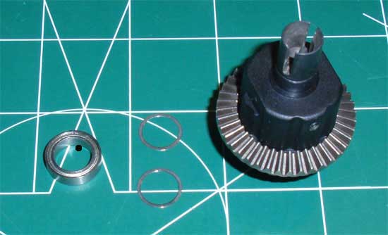
Add two shims and a bearing to the housing side of the diff. Make sure they seat all the way against the housing. Mine didn’t so I had to do a little sanding of the housing ‘nub’.
HPI Savage XS SS Online Build – Part 5
Part 5 of the HPI Savage XS SS deals with the rear gearbox. Its identical to the front gearbox build so it should go quickly.
Build Notes:
• In a few of the steps you will be pressing a locknut into a plastic ‘space’. To make this easier, align the locknut so the flat sides match the flat spots in the ‘space’.
Step 1
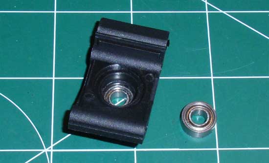
This is a pretty simple step; press the bearings into the bearing support.
Step 2
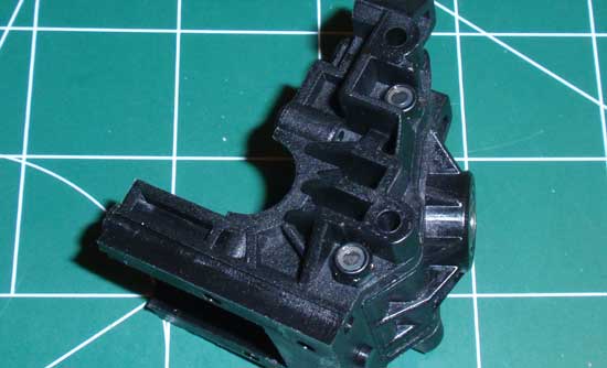
Take the bearing support, align it and secure with the two 3x35mm screws. The locknuts help secure the screws. Note the direction of the bearing support. I didn’t check it but I’m pretty sure it only fits in one direction.
Step 3
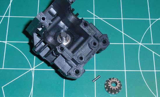
Find the longer outdrive and taller sun gear from the differential step. Slide the outdrive into place, insert the pin and press the sun gear over the pin. If you turn it over the sun gear might fall out. Put a dab of grease on the pin area and that should keep the gear in place.
Step 4
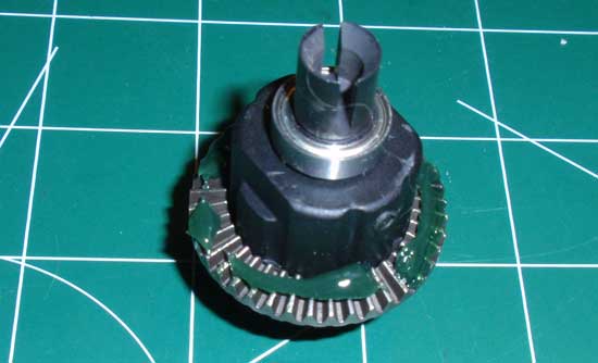
Take you built diff, liberally coat the gears with the supplied grease…
Step 5
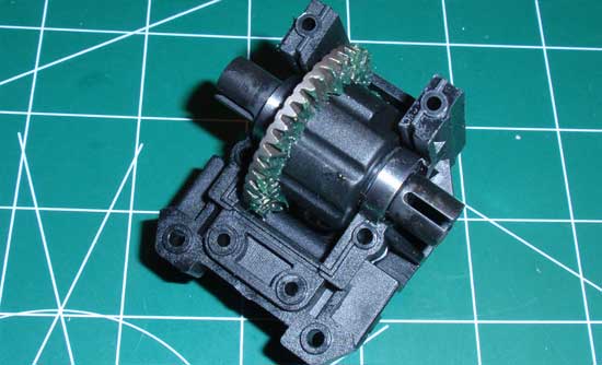
…and drop it into the gearbox. Note the direction of the diff. Also make sure that the bearings sit INSIDE the small lip. If it doesn’t fit, the bearings are not on all the way. Fix this before you move on.
Step 6
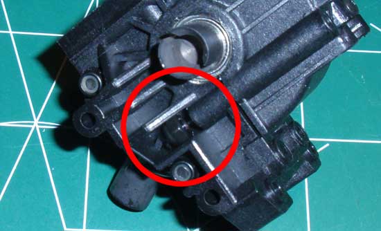
Attach the upper gearbox half into place. Press the locknut into the groove on the gearbox. As mentioned, lining up the flat spots will make this much easier. Do this on both sides.
Step 7
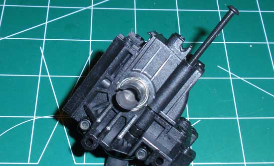
Secure the two halves with the 3x35mm screws.
Step 8
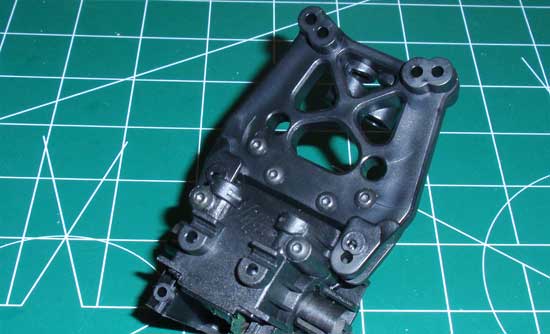
Insert a pair of locknuts in the rear of the front upper gearbox half. Now set the front shock tower into place and secure with the 4 screws. Make sure the 3x18mm screws are on top.
Step 9
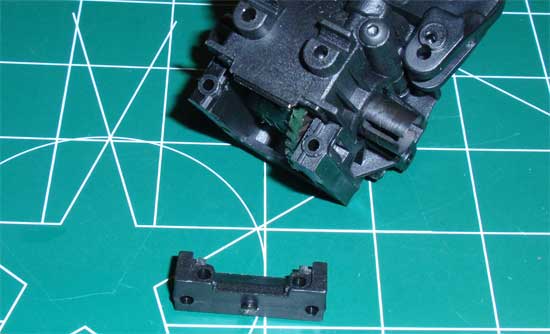
Press the lower gearbox mount into place. This piece is a little tricky so I had to trim off a little bit of plastic to make it fit.
HPI Savage XS SS Online Build – Part 6
Step 6 involves assembling the rear suspension. The build is very similar to the Step 3 (the front suspension), but thankfully has a few less steps. Lets get to it.
Build Notes:
• You will be building a left and right side of the suspension, however I will only be showing one side of the build.
Step 1
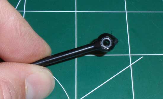
We start off the build with the CVDs. Put a bit of black grease on the cross joint and push it through the axle as shown. A set screw threads into the cross joint, but only from one direction (or the open end). Make sure you insert the cross joint with the ‘closed end’ first. This will avoid getting any grease on the threads.
Step 2
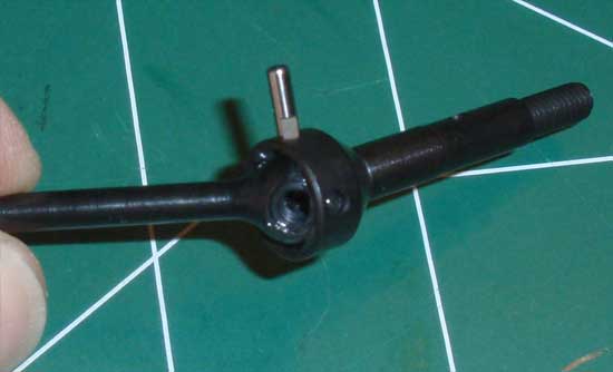
Apply a liberal amount of black grease on the axle ‘ball’ and insert it into the axle. Take your cross pin and insert it as shown. Make sure to line up the flat spot with the ‘open end’ of the cross joint.
Step 3
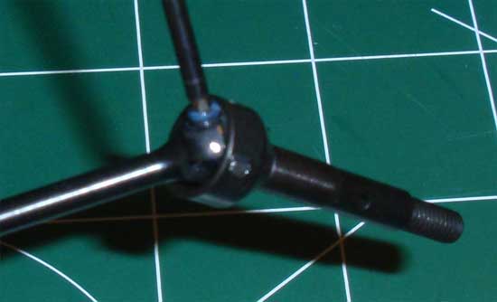
Apply a dab of threadlock onto the set screw and insert it as shown. Make sure the set screw contacts the flat spot of the cross pin. Build two of these.
Step 4
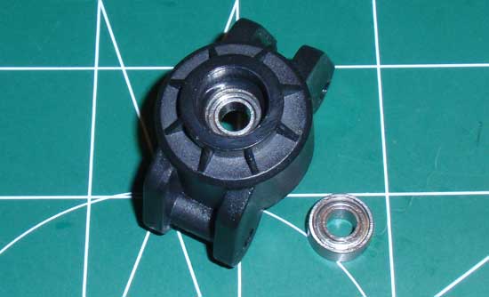
Press the two bearings into the rear hub carrier.
Step 5
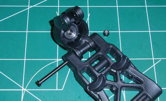
Take one of the suspension arms and attach the hub carrier as shown. Note the direction of the suspension arm.
Step 6
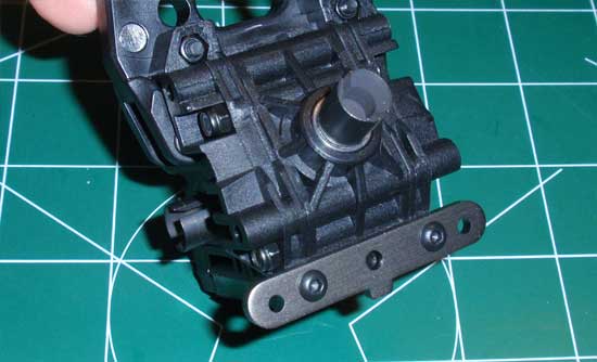
Attach an arm brace to both the rear of the assembled gearbox…
Step 7
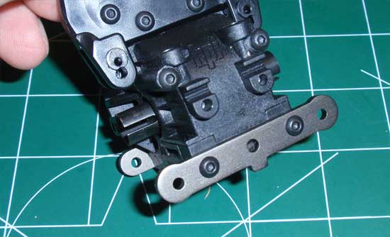
…and the front. Notice the front brace is slightly different than the rear one. Don’t get these mixed up.
Step 8
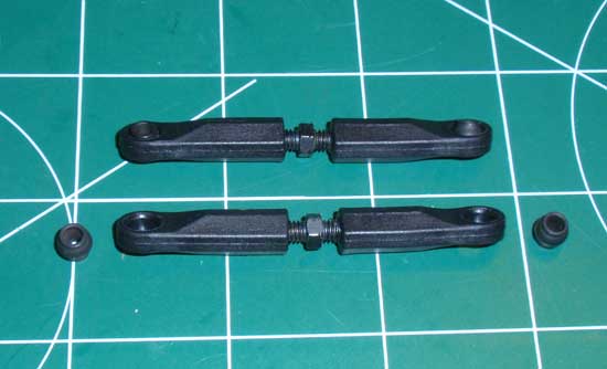
Assemble the camber links per the instructions.
Step 9
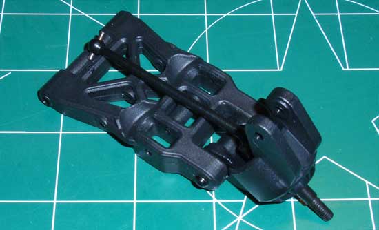
Slide the CVD into the hub carrier as shown…
Step 10
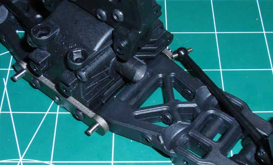
…then slide the arm between the arm braces and slide the long hinge pin in place. If the arm does not slide in smoothly, loosen the arm mount brace screws 1/4 turn and try again. You want the arm to slide in but still have a somewhat tight fit.
Step 11
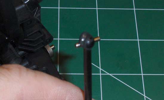
Add a bit of black grease to the ball of the CVD…
Step 12
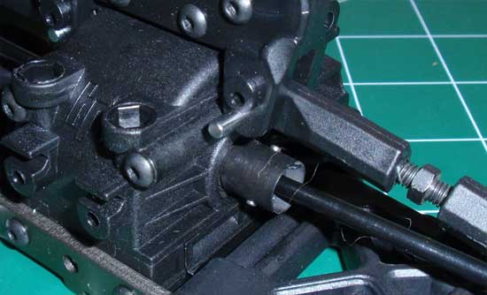
…and feed it into the diff outdrive. Take one of the camber links and slide it into position on the shock tower. Insert a camber pins to lock the camber link into place…
Step 13
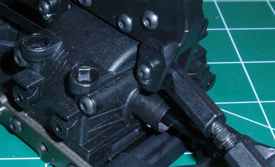
…followed by a 2.5x4mm screw. This screw keeps the camber pin in place.
Step 14/h3>
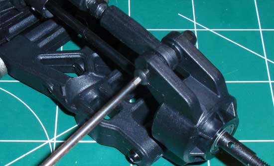
Swing the camber link into place and secure in the hub carrier.
Step 15
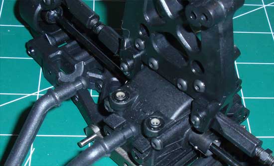
Press a pair of locknuts into the top of the gearbox case. Make sure they are seated all the way down. Take the rear bumper brace and feed it into the two holes in the shock tower.
Step 16
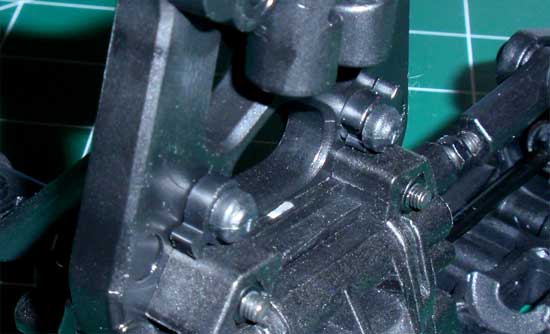
Secure with the pair of plastic c-clips.
Step 17
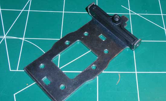
Attach the plastic mount to the metal skid-plate brace. Not the direction of the mount.
Step 18
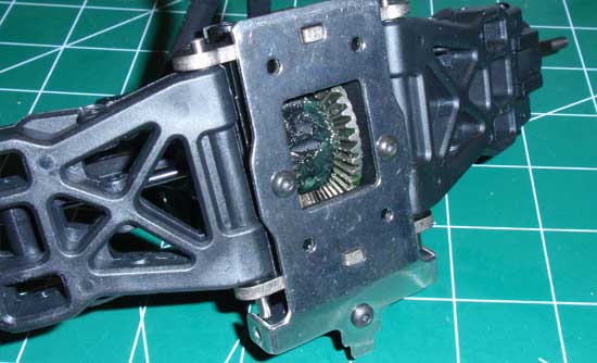
Attach the metal skid-place brace to the bottom of the gearbox. The plastic mount (you attached in Step 100) should be towards the front of the gearbox.
Step 19
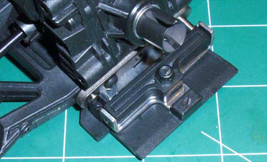
Locate the ‘box’ on the plastic skid plate. Insert the tab on the rear of the metal skid-plate into the box as shown…
Step 20
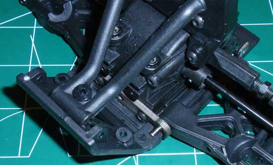
…and press the gearbox down and into place. The hinge pins should drop into the grooves in the plastic skid plate. You may need to slide the pins slightly forward or back to make them fit.
Step 21
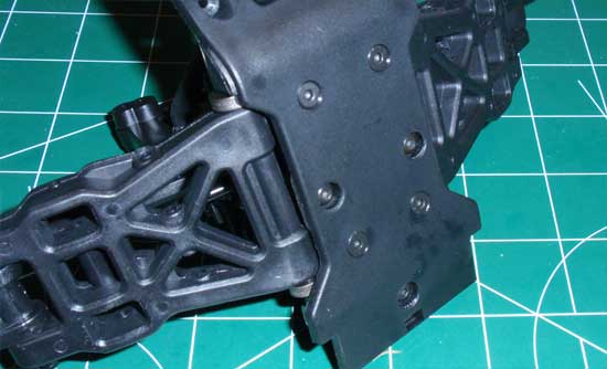
Secure the plastic skid plate to the gearbox with the 4 screws.
Step 22
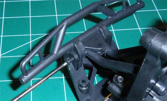
Swing the bumper brace into place and secure to the rear bumper with the 3x18mm screws.
HPI Savage XS SS Online Build – Part 7
In Step 7 we will be putting together the 2 halves of the chassis as well as installing the servo and brushless motor. There are a few tricky spots here to pay attention to so make sure you read the notes for each step.
Build Notes:
• In a couple of the steps you will be advised NOT to tighten the screws all the way down. Keep an eye on these steps…it will make building the XS SO much easier.
• With some kits you can continue the build without electronics; not this one. You will need the servo and motor, and I would HIGHLY suggest turning everything on and centering the servo now. If it is not centered when installed in the truck, you can do it without removing it but it is a bit of a pain.
• Pay close attention to the step where we piece the two chassis halves together with the steering. It is a bit tricky to line up the steering posts so take your time. If you don’t line them up you’ll end up with severly bound steering.
Step 1
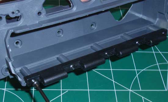
We start this build with the attachment of the battery box swivel rail. 5 screws and you’re moving on.
Step 2
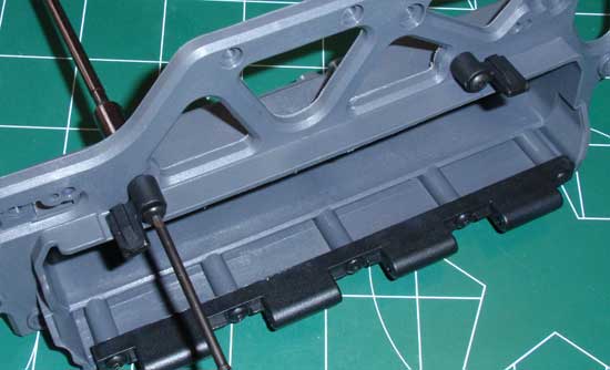
Next attach the two battery door swivel locks as shown…
Step 3
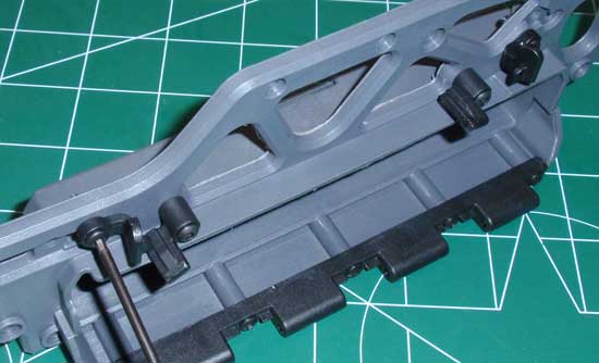
…followed by the battery door swivel lock locks. These will keep the swivels from swiveling while you’re driving.
Step 4
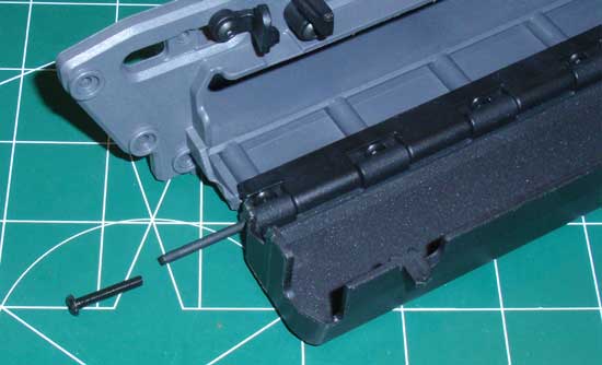
Line up the battery door and slide the flexible pins in place (one on each side). Press them in farther with the 3x18mm screw, then tighten the screw into place.
Step 5
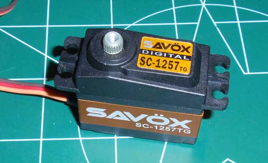
A quick pre-install look at the powerful Savox SC-1257MG steering servo. I show you this now because once the XS is completely built you won’t see the servo again. This is also a good time to center the servo (see the Build Notes above for this step).
Step 6
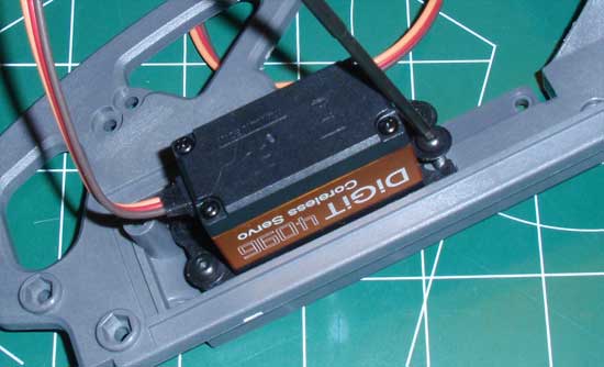
Slide the servo into place and secure with the four 3x12mm screws. Not the direction of the output shaft during the install.
Step 7
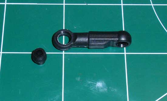
Build the drag link. No exact length was given so I threaded the ballcups in until they touched.
Step 8
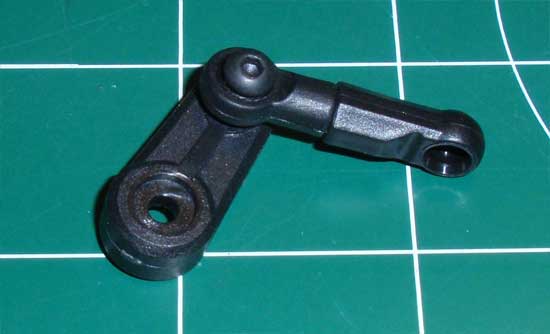
Thread the 3x12mm screw through the open-ended ballcup and into the servo arm. Make sure you choose the servo arm made for your servo.
Step 9
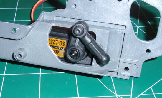
Attach the servo arm to the servo as shown.
Step 10
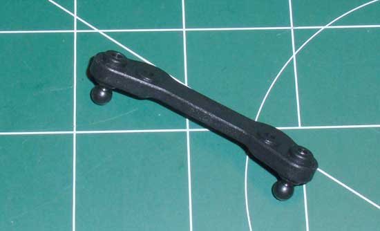
Build the bellcrank link as shown.
Step 11
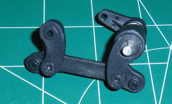
Attach the servo saver arm assembly and the opposite steering arm to the bellcrank link. HPI has graciously built the servo saver for us. One less step to worry about.
Step 12
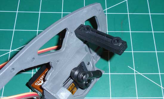
Attach the upper steering support to the chassis as shown. Note the direction of the steering post holes (towards the front).
Step 13
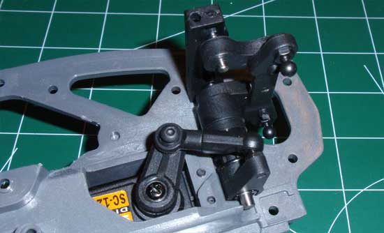
Slide the steering assembly into place and attach the drag link to the servo saver.
Step 14
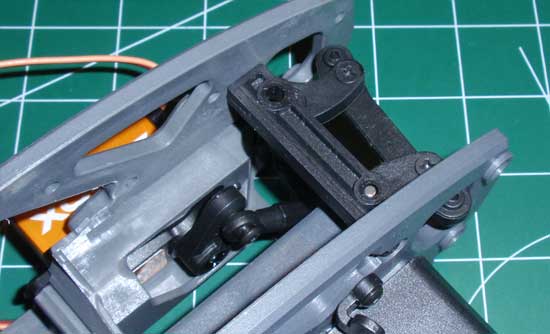
Align the steering posts with the lower mounts and slide the chassis halves together. The lower mount is keyed to the chassis and it’s not the easiest thing to assemble. Take you time and it’ll finally pop into place. Secure with the two 3x12mm screws. Give a quick look to make sure your steering posts have seated in the holes in the mounts.
Step 15
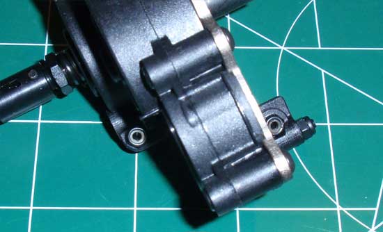
HPI has also pre-assembled the gearbox for us. This will save alot of build time for sure! Take a pair of the locknuts and press them into place on the gearbox as shown.
Step 16
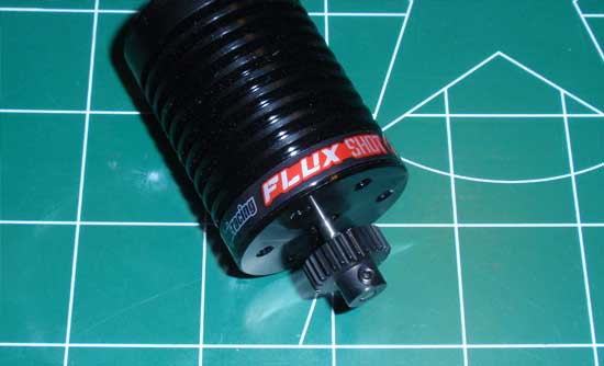
Attach the pinion to the motor. The XS comes with two pinions but since I wanted some stupid speed with this thing, I chose the biggest pinion.
Step 17
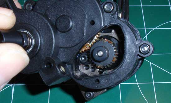
Slide the motor into place and, using the pinion-size guide in the manual, secure the motor into place. If you did it right the gear mesh will be automatically set for the gear set you are using. The gooey stuff inside is gear grease…shouldn’t be a problem but just try to keep it in the gearbox.
Step 18
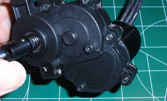
Once you have the motor locked in place, attach the gear cover.
Step 19
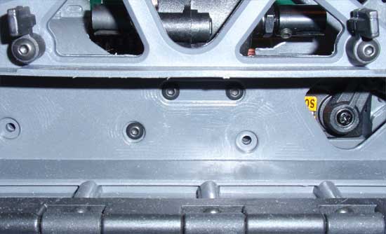
Wiggle the gearbox into place and attach it to the chassis plate using the 3 screws as shown. Don’t tighten them down all the way just yet.
Step 20
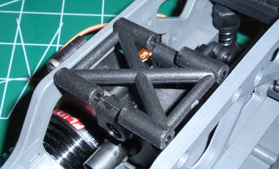
Drop the cross brace into place.
Step 21
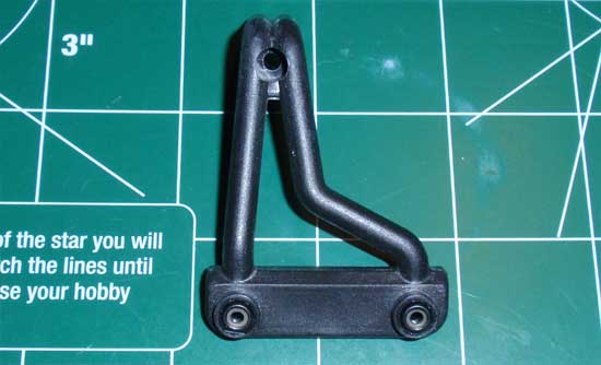
Press a pair of locknuts into the rollbar/carrying handle.
Step 22
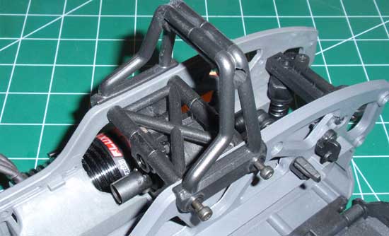
Place both sides of the carrying handle into place and, using the two 3x64mm screws, slide them all the way through the chassis (and cross brace) to the other side.
Step 23
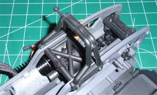
Secure the top of the rollbar/carrying handle as shown. You can now go back and tighten the screws for the gearbox you left loose in Step 124.
HPI Savage XS SS Online Build – Part 8
Step 8 revolves around attaching your previously built front and rear clips to the center chassis. We will also be installing the drive bones that go from the center transmission to the front and rear gearboxes.
Build Notes:
• When installing the drive bones, don’t forget to put a liberal amount of grease on the ball and pin section of the bones. Most of this will fling out the first time you pull the trigger but enough will stay to help lubricate the metal-to-metal surface.
Step 1
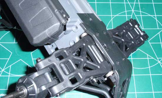
Since the rear of the XS is a little easier to work with (no steering link or components in the way), I started with this part first. Take a look at the inside of the chassis where the rear clip mounts. You’ll see an odd boxed shaped area…this is where the mounting point on the rear skid will ‘snap’ into place. So, start by sliding the upper portion of the clip into place and rotate it down so the skid plate ‘snaps’ into that boxed area. It’s a little tricky and does require a bit of grunt to make it work but it will snap in there. Make sure it is fully seated (as shown) before moving on.
Step 2
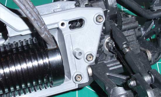
Press the 3 locknuts into the chassis as shown. These are a nice, tight fit so they should stay.
Step 3
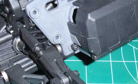
Slide ONE of the long 3x58mm screws into the bottom hole as shown. Do NOT tighten it down all the way yet…we want to use it as a pivot point for the next step.
Step 4
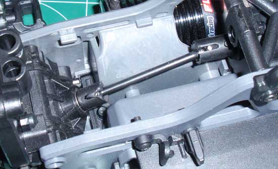
Grab one of the center driveshafts and slap some grease on the ends of it (both shafts are the same length). Now gently ‘flex’ the rear clip away from the truck and pop the driveshaft into place. Once you have it in place, install the other 2 3x58mm screws and tighten all three of them down.
Step 5
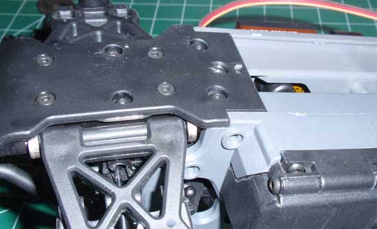
Attaching the front clip is the same as the rear, but pay close attention that the steering links and components are where they’re supposed to be (and not lodged inbetween the arm or something). Rotate and snap it into place.
Step 6
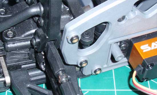
Press the 3 locknuts into place.
Step 7
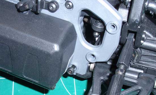
Insert ONE of hte 3x58mm screws but don’t tigthen it down yet.
Step 8
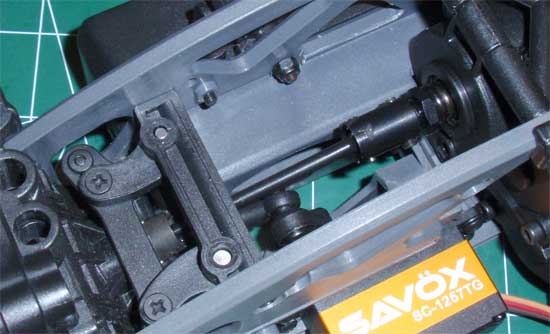
Grease the drive shaft and up gently flex the front clip away to install. The front will be a tiny bit more difficult than the rear but shouldn’t be to bad. Install the other 2 3x58mm screws and tighten all 3 down.
HPI Savage XS SS Online Build – Part 9
In Step 9, we will be installing the Futaba receiver and Castle Creations Mamba ESC. This step requires a little patience as you’ll see early on, but take your time and it shouldn’t be all that hard.
Build Notes:
• If you don’t read ANYTHING on this page, read this: Insert the rubber grommet from the INSIDE of the sealed box. Really. I tried installing it from the outside and after about 30 minutes gave up…but then tried it from the inside and it took about 3-4 minutes. Still a long time but WAY easier.
• The ESC holder can handle quite a few different ESC’s. Although the HPI Q-Base Flux Brushless ESC fit, it was a tad tall and I ended up having to flex the plastic ‘top’ a bit to get it to work over the top of the installed fan unit.
Step 1
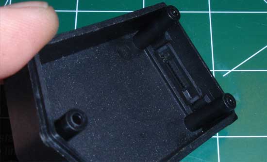
The first step is to install the rubber grommet into the waterproof box. This was a major pain but, as I described in the Build Notes, installing it from the inside was the only way I could get it to fit. Go ahead and do that now. I’ll wait an hour before we continue…
Step 2
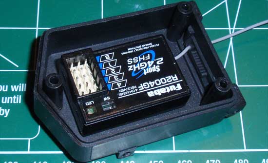
Now that you’ve probably thrown the box across the room, go get it and install your receiver. Install the antenna through the rubber grommet as shown and tape the receiver to the box.
Step 3
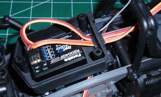
Set the receiver box into place and feed the servo and ESC leads into it as shown (don’t forget to plug them in). Leaving as much of the leads outside of the box (for now) will make it easier to deal with.
Step 4
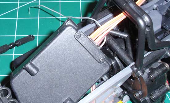
Flip the receiver box over and screw on the lower grommet holder. This ensures the grommet will not come loose or let any water in.
Step 5
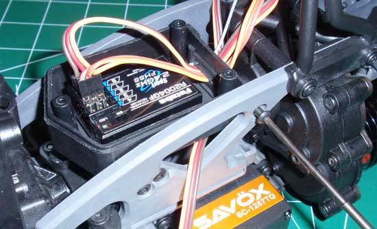
Flip the box back over and attach to the chassis with the 4 screws.
Step 6
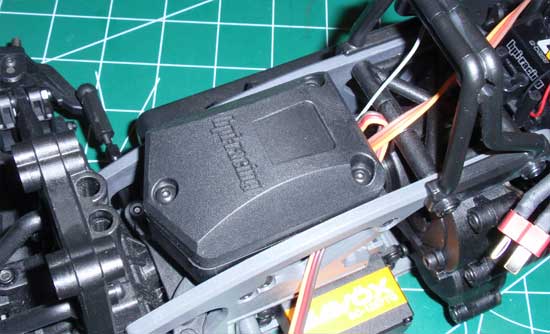
Attach the upper rubber grommet (between the box and lid) and screw the lid into place.
Step 7
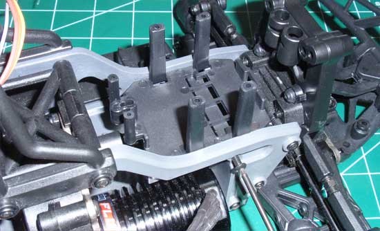
Attach the ESC mount to the chassis as shown.
Step 8
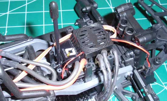
Using more of the double-sided tape, install the ESC.
Step 9
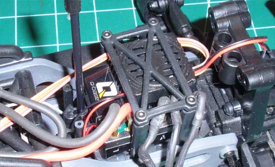
Connect your motor wires to the ESC (however you do it with your setup), and install the ESC holddown lid. Again, the HPI Q-Base Flux ESC was a little tall so that’s why the top looks distorted. I also used slightly longer screws to ensure it would keep the lid in place.
Step 10
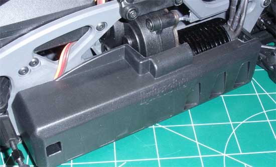
Attach the motor/servo cover with the 2 screws as shown in the manual.
HPI Savage XS SS Online Build – Part 10
Step 10 involves building and attaching the front and rear shocks. There’s nothing new or complicated about the shocks so it’s a pretty straightforward build.
Build Notes:
• Shocks involve shock fluid which, if you’re not careful, can easily get all over the place. Have some clean towels ready for clean up.
Step 1
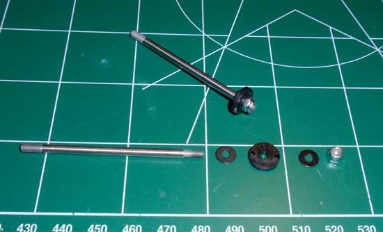
The first step is to build 4 shock shaft assemblies. Take the shock shaft and, on the end that has the smaller threaded area, slide the parts on as shown: steel shim, piston, shim, locknut. Tighten down the locknut. You can go pretty tight here; we don’t want the piston wiggling around at all. Build 4 of these.
Step 2
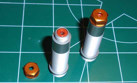
Place two red o-rings into the bottom of the shock body as shown. Drip a drop of two of shock fluid down into the center of the o-rings and screw the lower shock cap into place. Build 4 of these.
Step 3
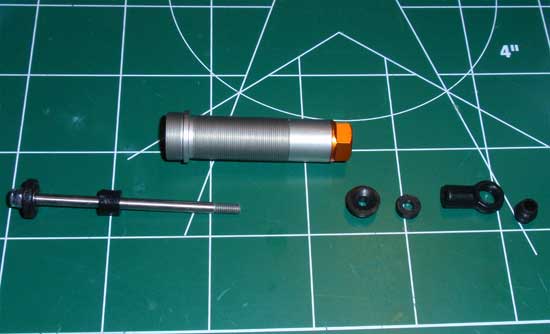
Slide one of the rubber downstops onto the shock shaft as shown. Take the shock shaft and SLOWLY feed it through the shock body and through the o-rings at the bottom of the shock. Once through, plunge the shock shaft a couple times to get it coated with the shock fluid you installed in Step 148. Now feed the two outer rubber bump stops onto the shaft (note the direction of the first bumpstop). Screw the shock eyelet onto the shock shaft and press the shock eyelet ball into place. Build 4 of these. Make sure they are all the same length; if they’re not, you can tighten or loosen the eyelets to adjust the length. WASH YOUR HANDS THOROUGHLY WITH SOAP AND WATER BEFORE THE NEXT STEP!!
Step 4
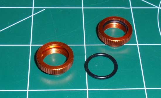
We will now press the black spring collar o-ring into the spring collar nut. This is much easier if you’re hands are not covered in shock oil so if you haven’t yet, WASH THEM! Build 4 of these and screw them onto the shock bodies. If they feel sticky, apply a small drop of shock fluid to the inside of the collar and thread them on.
Step 5
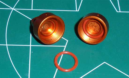
Press the orange o-ring into the shock cap as shown. This is a much easier step than Step 150. Build 4 of these.
Step 6
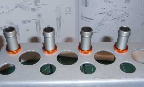
Set the shocks in your shock stand (you do have a shock stand, don’t you?) and fill them up with shock fluid. Plunge the shock shaft slowly up and down to release any air bubbles below the piston. Place back in the stand and let sit for a few minutes. Once the bubbles have risen to the top (and popped), fill thoe shocks up again to the top and screw the shock tops on about 90% of the way.
Step 7
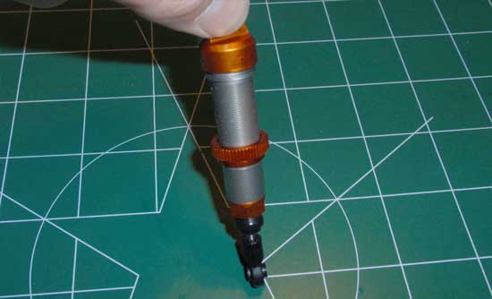
Pull each shock from the shock stand and slowly collapse the shock shaft into the body as shown. You should see some shock fluid pour out the bleeder hole in the side of the shock cap. If you don’t you may not have enough oil in them. Open and fill with oil to the top of the body and repeat. If the shock won’t collapse, unscrew the cap another 1/2 turn and repeat this step. Once you have bled the shocks, tighten down the shock cap.
Step 8
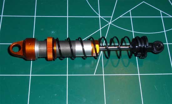
Install the spring and lower shock spring retainer on all 4 shocks.
Step 9
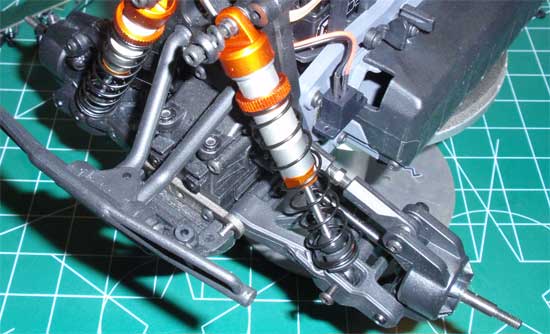
Attach the shocks to the Savage XS SS as shown. Make sure you add the o-rings to the top of the shock mount.
HPI Savage XS SS Online Build – Part 11
The final step in the HPI Savage XS SS build is the body, wheels and tires. HPI includes all three but you’ll need to glue the tires to the wheels and paint and mount the body.
Build Notes:
• Gluing up the tires is a simple but sometimes messy step. I always recommend people picking up a set of the CompetitionX Gloo Toobs. These little glue tips allow you to precisely apply glue where you want it as well as actually SAVING the amount of glue you use.
• If you’re a hero painter like me (NOT!), you can probably whip up something cool on the clear XS body. If not, there are plenty of painters on the web that can do a killer job for you.
• You may notice that the end of this build there is nothing showing me mount the body on the truck. Well, that’s because the original XS body seems to have gone missing in the mail and a spare is on it’s way. To complete this build, I just left it out. Check out the review of HPI’s Savage XS SS for the paint that made the final cut.
Step 1
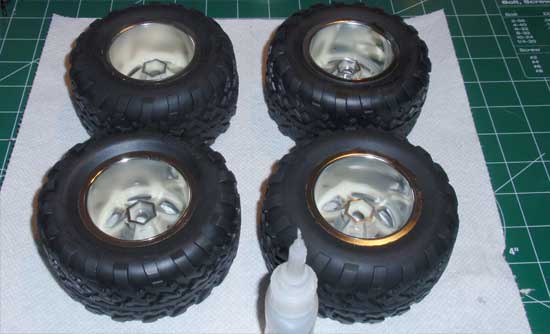
The first step in the final step is to assemble and glue up the XS tires. Stuff the insert into the tire followed by the wheel. Make sure the bead of the tires is seated correctly in the wheel groove before gluing. Let each side dry for about 20 minutes before flipping over and gluing the opposite side.
Step 2
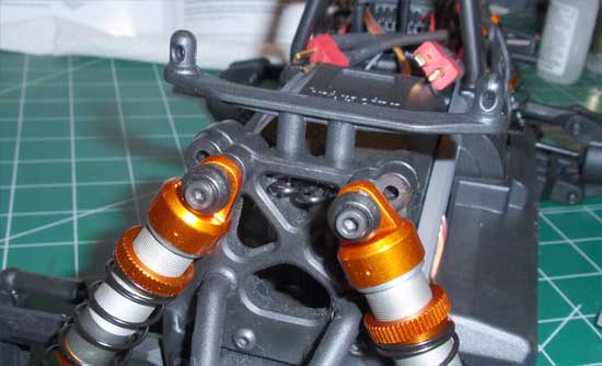
Feed the body mounts into the top of the shock towers and lock in place with the body clips. The body height is adjustable but I installed them according to the instructions (2nd hole from the top).
Step 3
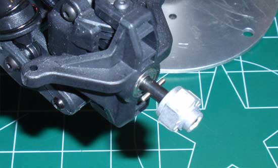
Slide the wheel pin through the hole in the axle and capture it with the wheel hex adapter. Do this on all four corners of the XS.
Step 4
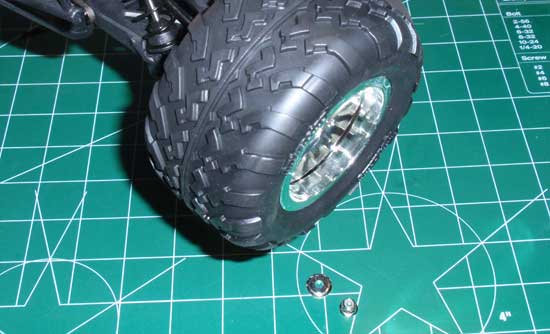
Slide the freshly glued wheel and tire combo into place and secure with the locknut. Don’t forget to install the washer BEFORE the locknut. This washer helps distribute the pressure evenly so it won’t fatigue the center of the wheel.
Step 5
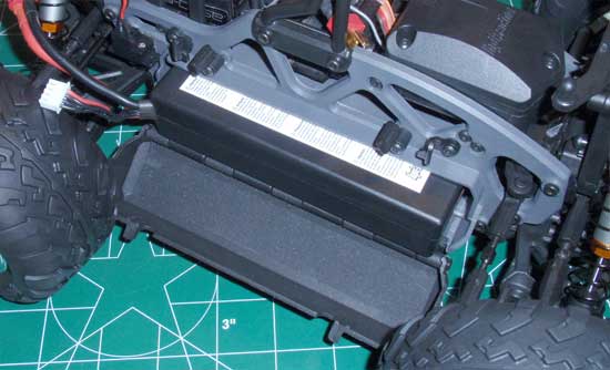
Take your 2S (or 3S) battery and slide it into the battery compartment.Make sure the battery leads are towards the front.
Step 6
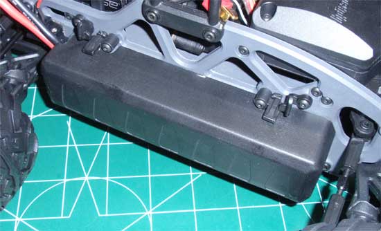
The final step is to close the door to the battery compartment and lock it in place with the ‘flip’ locks. Make sure the battery leads feed out through the openings in the battery door.
And that’s it! You should know have a fully functional, rip-roaring HPI Savage XS SS! Word of caution: this truck is addicting! It is SO fast with a 3S that you may never want to lift!
I hope this build has helped you build yours. Don’t hesitate to ask any questions if you have them! Good luck.

