
Team Durango DEST210R Online Build
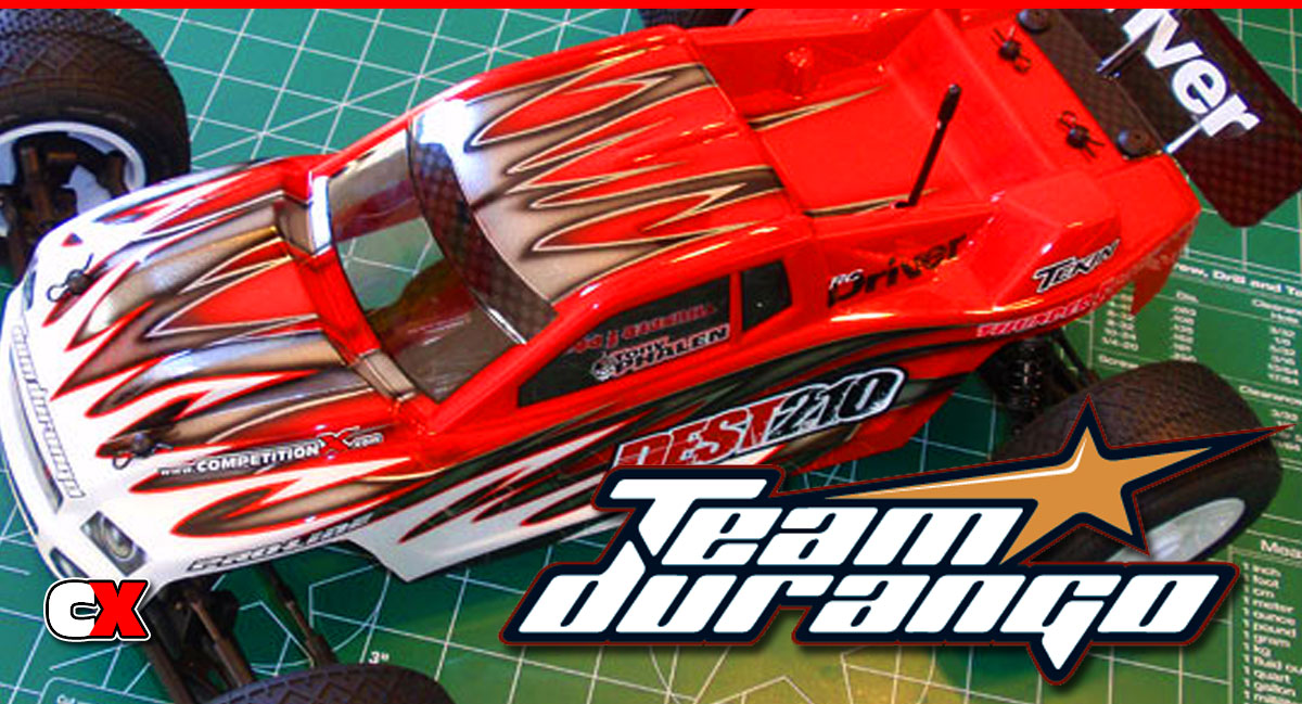
on the 2WD Stadium Truck group with the release of the DEST210R. Based on the ultra-competitive DESC210R, the DEST210R should have no problem reaching the podium.
Follow our step-by-step build up right here on CompetitionX. Testing and my final thoughts will be posted in an upcoming review.
Team Durango DEST210R Online Build – Part 1
The steering is the first thing we need to build on the FT SC10 4×4. Because it is buried DEEP in the chassis, you will need to have your servo for the first part of this build.
Build Notes:
• Since the instructions are step by step, I would suggest emptying the contents of each bag (as you get to that step) into a designated area so it is easier to find the parts you need. For example, the first part of the build uses Bag A. Empty that out to make it easier to find the parts. When it comes time for Bag B, do the same.
• Some of the screws will thread into aluminum parts. Have some blue thread-locking compound handy to help prevent those screws from backing out while you run the truck.
Step 1

Find the two Steering Bellcrank arms and insert one of the bearings as shown. Insert the small plastic shim down inside the arms and press the 2nd bearing into place. Make sure the plastic bushing is seated correctly before inserting the bearing.
Step 2

Insert the 3x18mm screw through the Servo Bellcrank Support followed by a metal shim, the Servo Bellcrank Arm and then another metal shim. The first side will be easy; the second will take a little patience. The Servo Bellcrank Support is a little flexible, allowing you to flex it enough to get the screw to feed into the Servo Bellcrank Base.
Step 3

Insert the ballend into the left Servo Bellcrank Arm.
Step 4

Thread both ballends through the metal Servo Bellcrank Connecting Arm. It’s hard to see in the instructions (mine are quite dark) but the ballend goes through the center hole. Make sure you have it mounted in the same location on both sides.
Step 5

Drop the ‘tophat’ spacer into place as shown…
Step 6

…and screw into place with the 3x8mm screws. Don’t forget the washers. You’ll want to add a small dab of threadlocker here to keep the screws in place. DO NOT over tighten. There must be free movement in this assembly.
Step 7

Take the Chassis Plug and attach it to the Chassis. The instructions call out the part as 320141-4, however that is not correct. The correct ‘tree’ number is 320121-4.
Step 8

Now drop the Steering Bellcrank Assembly into place as shown. There are locating pins on the bottom of the Steering Bellcrank Base. Once you have it set into place, secure with the 3 3x6mm screws.
Team Durango DEST210R Online Build – Part 2
The next setp involves installing the steering servo into the truck. I can definitely say this is the most involved steering servo install I’ve ever done, but it is quite cool! This thing isn’t going anywhere!
Build Notes:
• I am using one of Futaba’s killer brushless servos, the BLS157HV. Only the best for my stadium truck.
• It’s a good idea to pick (and test fit) the correct servo horn prior to starting this step. This makes this step easier and helps keep the build moving along smoothly.
• It is also a good idea at this point to center your servo. You can do this by hooking up your electronics package, turning on your transmitter and making sure the servo is centered.
Step 1

Start this step by installing the ballend into the correct Servo Horn.
Step 2

Attach the Servo Horn to the servo and use the screw that came with your servo. Again, make sure your servo is centered before attaching the Servo Horn.
Step 3

The servo in the DEST210R is angled (unlike most off road cars where just the Steering Bellcranks are angled). Secure the servo to the Servo Mounts but do not tighten down the screws yet.
Step 4

Build the Servo Drag Link with a 2mm gap per the instructions. Now snap one end of it onto the ballend on the Servo Horn.
Step 5

Mount the Servo Mount-Servo Mounts to the chassis. These key into small nubs on the chassis.
Step 6

Take your servo assembly and slide place it in the chassis, sliding it down into the slots as shown. If it seems difficult, loosen the chassis-mounted Servo Mounts and try again.
Step 7

Secure the servo with the two 3x10mm screws. You can re-tighten the screws to the chassis-mounted Servo Mounts if you loosened them in the last step.
Step 8

Tighten down the Servo Mount screws.
Step 9

Snap the Servo Drag Link onto the Steering Rack.
Team Durango DEST210R Online Build – Part 3
ring Rack.
The step involves building the front shock tower and attaching it to the front bulkhead. We’ll attach that final assembly to the chassis. Pretty simple 6-step process.
Build Notes:
• None.
Step 1

Start by attaching the two ball ends to the Shock Tower. Use the inner mounting hole and don’t forget to add the two shims.
Step 2

Next, attach the front Body Mount Support. It is directional so be sure you have it mounted the right way.
Step 3

Attach the completed Shock Tower to the Shock Tower Support.
Step 4

Find the front Bulkhead and arrange it as shown in the picture. Notice the recessed ‘nub’ holes. The Shock Tower assembly has matching ‘nubs’ located on the bottom of it. Press these two parts together. Again, make sure the front Bulkhead is correctly orientated.
Step 5

Place the front Bulkhead/Shock Tower assembly on to the Chassis and secure with the 4 3x18mm screws.
Step 6

Finally, attach the Shock Tower Support’s ‘arms’ to the side of the Chassis. The top-hat looking piece helps center the screw.
Team Durango DEST210R Online Build – Part 4
On to the front suspension. This part of the build includes the front suspension arms, steering knuckles and caster blocks. Pretty simple, straightforward steps.
Build Notes:
• The suspension arms are made of a pretty strong plastic; you’ll notice this when you try and screw in the droop screws. I would suggest putting a drop of grease on the droop screws prior to inserting. You don’t want the tight plastic to stress out your hex-driver and snap the tip off.
Step 1

Arrange the front Suspension Arms as shown and tap the droop screw in. Since it doesn’t give a starting point, I would suggest tapping it all the way until it is flush with the arm boss (see right side arm). This will give you a good starting point.
Step 2

Take the 2 longer Hinge Pins and feed them into the Suspension Arms and Bulkhead as shown.
Step 3

Fit the aluminum Hinge Pin Brace into place and follow that up with the front Hinge Pin Cap. Note the direction of the Cap.
Step 4

Take your left and right Steering Knuckle and press Bearings into both sides.
Step 5

This step is a bit tricky. First, press the two top-hat bushings into the holes of the Caster Block. You’ll want to feed them into place from the ‘inside’ of the Caster Block. Now insert one of the 3x12mm screws through the top of the Caster Block (and top-hat bushing), slide a plastic washer over the screw and then fit the Steering Knuckle into place. Screw the 3x12mm screw in until it is lightly snug. Repeat for the lower screw. Once both screws are in place, tighten each one 1/4 turn (rotating from the top screw to the bottom screw) until both are tight. Make sure there is no binding in the Steering Knuckle.
Step 6

Feed the ball end through the plastic washer and into the Steering Knuckle’s arm. Attach the locknut and tighten down. The locknut will fit into a locknut-shaped recess in the bottom of the arm.
Step 7

Feed the ball end through the Caster Block and secure with the locknut. Yes it’s hard to see what hole; use the outside one.
Step 8

Take the 3x10mm screws, slide the washer over it and feed into the Axle. A dab of thread-locking compound here is a good idea.
Step 9

Now slide the Axle assembly through the plastic washer and into the Bearings in the Steering Knuckle.
Step 10

Slide the Wheel Hex Adapter over the axle and secure with the Axle Pin. Make sure you put the Wheel Hex Adapter on the Axle BACKWARDS as shown. Yes, this might seem odd to some of us but this is how it works.
Step 11

Choose which Caster Block setting you want and slide it into the Caster Block. Make sure you orientate the left and right sides the same when building.
Step 12

Another tricky step. Start by sliding the Hinge Pin through the Suspension Arm and into the Caster Block. All 4 of the shims go BEHIND the Caster Block…this is where it gets tricky. The easiest way I found to do it was to lay all 4 shims together, slide them into the gap and, while pushing the Caster Block towards them, pinch all 4 between the Caster Block and the Suspension Arm boss. Once you get them in place, slide the Hinge Pin all the way through and secure with the 2.5x4mm screw.
Team Durango DEST210R Online Build – Part 5
The rear suspension of the DEST210R is as simple to assemble as the front.
Build Notes:
• You will need to use black grease to build the rear drive axles. Have some paper towels available to help with clean-up.
• Pay close attention to the direction of the rear suspension arms. Building these backwards means building them twice.
Step 1

Let’s start off by building the drive axles. Grab a dogbone and shoot some black grease into the open end. Take the coupler and slide it through the hole. Make sure the couple ‘pin’ hole is visable through the slot in the of the dog bone’s open end.
Step 2

Put a liberal amount of black grease on the ‘ball’ of the drive axle and insert it into the axle. Line up the axle hole with the coupler hole and slide the pin in place. Set both axles aside.
Step 3

Press the bearings into the rear hub carrier.
Step 4

Insert the ball end into the hub carrier. Use hole #3 (see set up sheet for hole numbers). Don’t forget to insert the plastic spacer!
Step 5

Slide the assembled axle through the hub carrier. Take the hex adapter and slide it onto the axle FIRST (note the direction). Line the hole in the axle up with the slot in the hex adapter and slide the pin into place. This is a pretty tight fit so the pin should stay in place.
Step 6

The next step involves the rear toe in the 210R. The rear toe block already adds 3 degrees of rear toe this is, in essense, extra toe. I would suggest starting with the 0 or -.5 degree toe insert. Make sure you insert both in the same direction in the rear hubs.
Step 7

Take your hub carrier assemblies and lay them out as shown. Now place the rear suspension arms out as shown, also. This step is to verify the correct arms are set for the correct side of the truck.
Step 8

Drive the Droop Screw into the arm (from the bottom). To start, screw it all the way down. This will also help out when attaching the arms to the chassis.
Step 9

Insert the 2.5x4mm screw into the Hinge Pin retaining hole on the outside of the arm. You can insert either screw first.
Step 10

Slide your Hinge Pin through the arm boss, through a pair of the Wheelbase Spacers, through the Hub Carriers and through the final pari of Wheelbase Spacers. Yes, it’s a bit tricky but MUCH easier than the front assembly.
Step 11

Insert the other 2.5x4mm screw to lock the Hinge Pins in place.
Step 12

Choose the inner Arm Mount you wish to use and secure it to the Chassis.
Step 13

Slide the inner Hinge Pin through the arm and cap each end with a Hinge Pin Ball. These are a very loose fit so a dab of grease will help keep them attached.
Step 14

Slide the arms into place, followed by the rear toe block. Secure with the pair of 3x8mm screws.
Team Durango DEST210R Online Build – Part 6
Part 6 deals with building the DEST210R’s ball differential. While I could have incorporated this with the gearbox build, I just figured it would be easier to keep things short and sweet.
Build Notes:
• The instructions mention a ‘Silicone Grease’ and a ‘Molybdenum Grease’. Typically, Silicone Grease is clear so that was easy to figure out, so that would make the Moly Grease the green stuff. However, there was also a container labeled ‘Gear Grease’…looking VERY much like the Moly Grease. You will need to use this in a later step so don’t get them confused.
• You will be using both black and diff grease while building the differential. Have some paper towels handy for esay clean up.
• While I did these steps in the order presented, some of you might want to do Steps 53-54 up front. I was able to get the C-ring to snap into place easily but I can see how it might be a pain.
Step 1
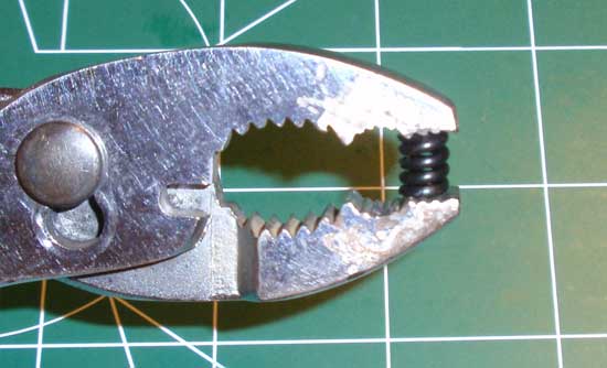
Take the diff spring and pre-compress it using a pair of pliers.
Step 2
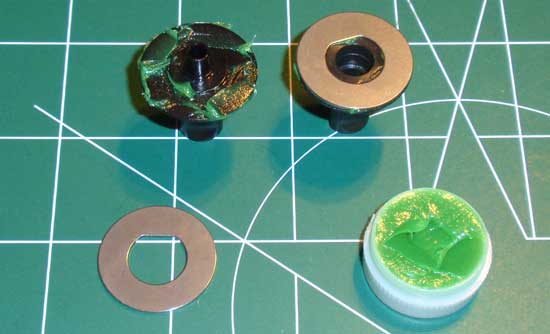
Open your Moly Grease and put a little on the outdrives where the rings set. Press the rings in place. The grease will help keep the rings from falling all over the place.
Step 3
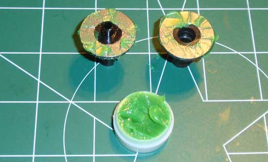
Once in place, coat the rings with the Moly Grease as shown.
Step 4
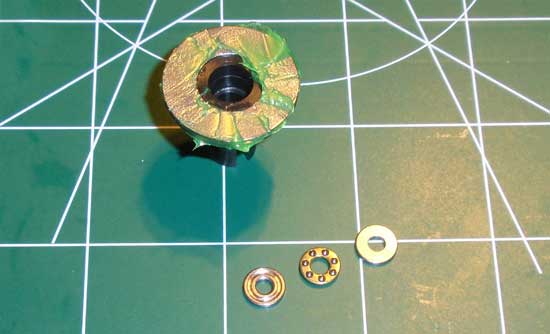
Find your thrust washers and bearing and assemble them as as shown, making sure to pack it full of black grease (more is ok here. Be sure that the ‘grooved’ areas point towards the bearing. Slide this assembly down inside the ‘female’ outdrive.
Step 5
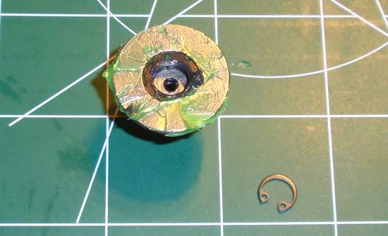
Tricky-step time. If you have a pair of C-ring pliers this will be an easy step. If you don’t, not so much. Take the C-ring and feed it into the opening. It obviously won’t fit, but if you take a pair of pliers (or socket wrench) you can slowly work it down in the groove. It is extremely important that this C-ring snaps into the groove in the outdrive!
Step 6
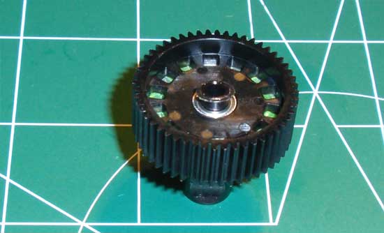
Take one of the 5x8x2.5 bearings and the 5x7x.0.2 shim and slide them over the nub on the male outdrive (no rude comments, please). Once seated, slide the diff gear on and over the bearing.
Step 7
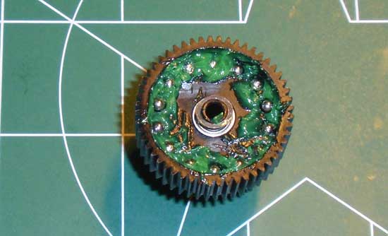
We want to make sure the diff had plenty of grease. Pack a liberal amount into each hole followed by the diff balls. You can also see the shim here from Step 55.
Step 8
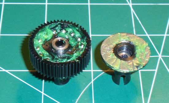
Slide the other 5x8x2.5 bearing onto the outdrive nub. Take the opposite outdrive and flip it over and into place, creating a complete differential. Make sure you keep the ‘flipped’ outdrive side face up…
Step 9
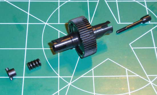
…because that’s the side the Diff Screw goes through. Slide it through the diff, the Diff Spring and into the Diff Nut. Clamp the differential together and SLOWLY tighten the Diff screw into the Diff Nut. Continue to tighten 1 full turn, working the diff after each revolution. When the diff is tight, it’s ready. Since it doesn’t say, I’m suggesting backing the screw off about 1/8th of a turn. That’s about typical for these types of differentials.
Step 10
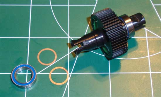
Final step; Slide a pair of copper Shims on each side of the diff followed by a 10x15x4mm bearing. That’s it…you’re done. Set the diff aside for the next step as we assemble the complete gearbox.
Team Durango DEST210R Online Build – Part 7
In this step we will be assembling the gearbox. The DEST210R allows you to build the gearbox in one of 4 configurations; Rear Motor 3-Gear (RM3), Rear Motor 4-Gear (RM4), Mid Motor 3-Gear (MM3) or Mid Motor 4-Gear(MM4). Each of these has it’s pros and cons, and you can read all about those here: Team Durango Motor Config, which I would suggest doing prior to starting this step. I chose to build it in the MM4 configuration not only because it seemed to be the style I wanted but more because it is completely different that any 3-gear, rear-motor setups I’ve ever driven.
Build Notes:
• You will be using some of the grease labeled Gear Grease in this step. Don’t get it mixed up with the other green ‘Moly’ grease.
• Pay close attention to the steps. Some of the instruction pages are for the RM3/RM4 build, others for the MM3/MM4 build. As mentioned above, this build is for the MM4. Your steps may vary.
• You will need some threadlocker and CA glue for this step. Have it ready and make sure you have a clean, covered work space. Glue and mom’s kitchen table are not a good mix.
Step 1

The first step is pretty tricky. Slide your assembled differential into the gearbox housing as shown. Tough, right? Do make sure, however, that the diff adjustment screw is facing towards you and not the the gearbox half.
Step 2

Press the 5×10 bearings into both of the idler gears.
Step 3

Slide the idler gear shafts into position (as shown), followed by a 5×8 gear shim.
Step 4

Slide your assembled idler gears into place followed by another 5×8 idler gear shim.
Step 5

Take the opposite-side gearbox case and start by pressing a 5×8 bearing into place.
Step 6

Align the flat spots and insert the top shaft into the layshaft gear. Smudge a bit of the gear grease onto the layshaft gear and drop the assembly into the bearing you just pressed into place in step 64.
Step 7

Combine the pair of gearbox halves together. Secure with the pair of scrwes. Don’t forget the washers.
Step 8

Slide the plastic motor mount spacer into place followed by the metal top shaft spacer and 5×11 bearing.
Step 9

Slide the 3 long screws through the case (don’t forget the shims). There are two different sizes here to make sure you get them in the correct holes.
Step 10

Slide the plastic spacer into place. It doesn’s say but I added a light dab of threadlock to the 3 long screws at this point. The align the screw holes in the motor mount and tighten. The threadlock will help keep these screws from loosening up.
Step 11

Does this step look familiar? It might, but this is an entirely different step; same idea though. Pre-compress the spring a few times.
Step 12

Take the top shaft screw and put a SMALL dab of CA glue in it. Quickly slide the pin into place before the glue dries. When I say small I mean SMALL! This pin needs to fit into a groove in the slipper plate and if you put to much glue it won’t.
Step 13

Slide the inner slipper plates onto the top shaft as shown. The inner one is the one without the writing on it.
Step 14

Slide the spur gear and slipper pads into place. Two pads go on the gear (one on each side) and are keyed into it. If they don’t stay, you can add a dab of black grease to keep them in place.
Step 15

Take the second slipper plate (the one WITH the writing on it) and slide it into place. Take you top shaft screw assembly (the piece you CA glued the pin into) and slide it all the way through the top shaft, making sure the gluee pin seats in the groove of the outer slipper plate.
Step 16

Using one hand to hold the slipper assembly tight against the motor mount, slide the shim-spring-shim-locknut pieces into place. Tighten the locknut down…
Step 17

…to about this point. There are no suggested settings so we’ll deal with this later.
Step 18

Attach your motor to the motor mount. Again, no suggested gearing settings to start with so you’ll either have to scour the web or test this on the track.
Step 19

Attach the gear cover. Notice there isn’t a hole for the slipper spring…AH! That’s because it sticks out of the other side of the gearbox. Pretty slick.
Team Durango DEST210R Online Build – Part 8
In Step 8 we attach the gearbox to the chassis. There is only one place the gearbox can mount but, depending on the configuration with which you built it (RM3, RM4, MM3, MM4) will designate how to attach it.
Build Notes:
• Pay close attention when mounting the gearbox. Make sure you are using the correct configuration to mount it.
• Depending on the size (and mounting) of your servo, you may or may not need to install the front battery stop. I couldn’t get it to fit while using the Futaba BLS157HV servo.
• These build notes are for the MM4 configuration. Some of the steps may vary depending on the configuration you build.
Step 1
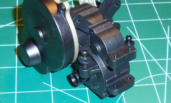
Start the install by attaching the ball ends to the gearbox. Don’t forget the 2 plastic washers on each side.
Step 2
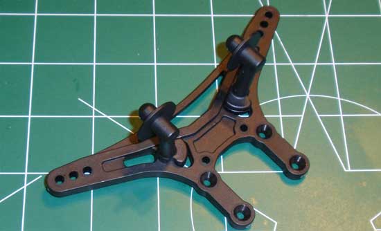
Attach the body mounts to the shock tower. Notice the direction of the shock tower for the MM4 build.
Step 3
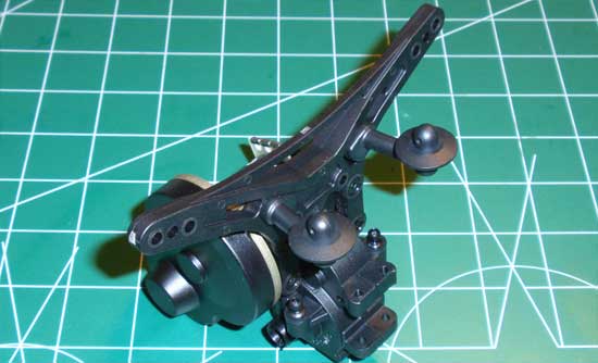
Attach the shock tower to the gearbox.
Step 4
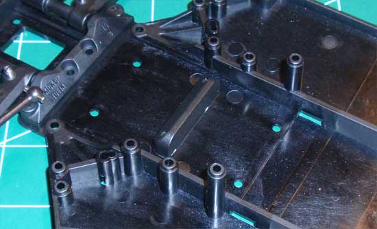
Install the front and rear battery stop. As I mentioned earlier, I could not get the front battery stop to fit because of the size of the servo.
Step 5
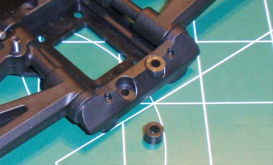
Take the two spacers and press them into place. They should be a slightly tight fit so you won’t have any problem with them falling out. If not, a dab of black grease will help keep them in place.
Step 6
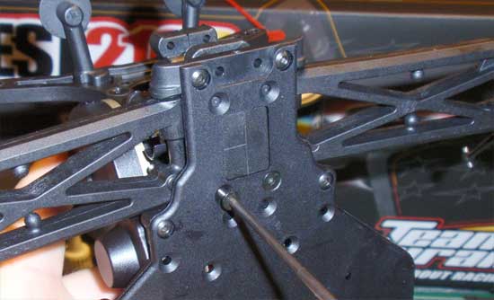
Drop the gearbox assembly into place and secure with the 2 3x10mm screws.
Step 7
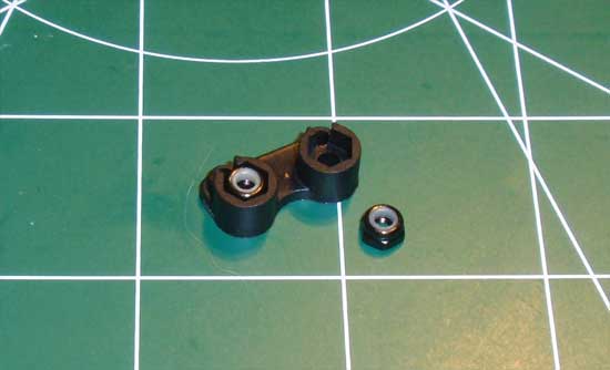
Press the two locknuts into the upper anti-roll bar mount.
Step 8
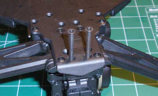
Set the rear bumper into place and feed the two 3x30mm screws up through the chassis about 3/4 of the way.
Step 9
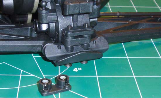
Place the lower anti-roll bar mount over the two screws followed by the upper anti-roll bar mount and tighten down the 3x30mm screws. No need to overtighten since the screws feed into the locknuts.
Step 10
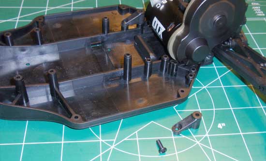
Place the chassis braces into place and secure with the 3x10mm screws.
Step 11
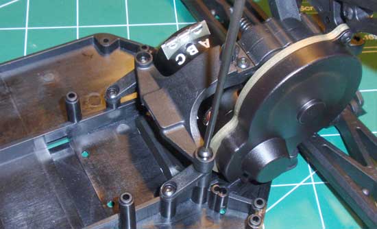
Drop the motor/rear chassis brace into place and secure.
Step 12
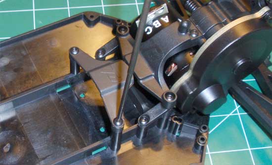
Set the battery brace locator into place and secure.
Step 13
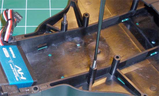
While not a step to mount the gearbox, we’ll put it here anyway since Durango has it here. Screw the battery brace thumbwheel setscrews into the chassis. Put them in about 1/2 way; we can adjust them later.
Team Durango DEST210R Online Build – Part 9
Step 9 consists of building the turnbuckles. Pretty simple and straightforward, but do yourself a favor and READ the page before building. I saw 4 sets of turnbuckles and spent a good 15 minutes looking for 4 sets of angled ball cups…only to realize that the bottom 2 sets were the SAME THING…just built different depending on the rear motor configuration. Oi…
Build Notes:
• All 3 sets of turnbuckles have a left and right side. Pay special attention that you build them that way.
• Not all given lengths are correct in instruction manuals, but the Durango ones seem good to start with.
Step 1
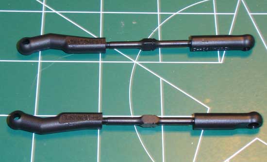
Build the front camber links…
Step 2
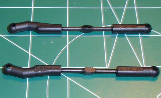
…followed by the front steering links…
Step 3
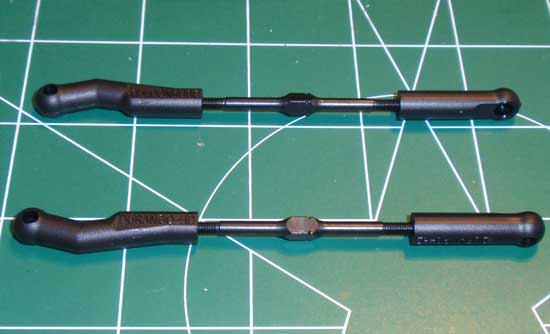
…and the rear camber links. Make sure you pay attention to which rear links you build depending on the motor configuration you’ve chosen.
Step 4
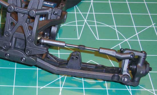
Pop the front camber links into place. Notice the location of the bent ball cup.
Step 5
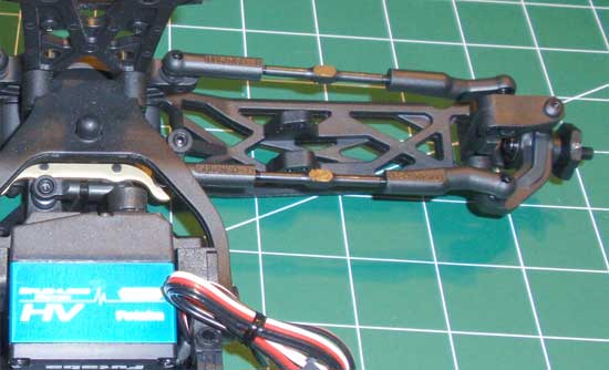
Pop the front steering links into place. Notice the location of the bent ball cup.
Step 6
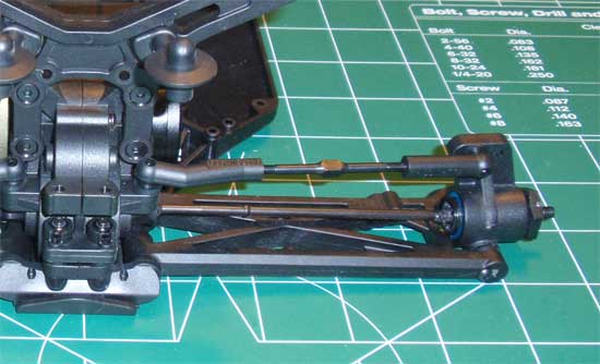
Pop the rear camber links into place. Notice the location of the bent ball cup.
Team Durango DEST210R Online Build – Part 10
The shocks are the single most important part of the suspension of the DEST210R. Mess these up and you’ll most likely be struggling out on the track! Take you time building the shocks!
Build Notes:
• The shock pistons all look very much alike. When removing them from the tree, snap off the #1 pistons and place them near the front shock shafts. Do the same with the rears. This will ensure you don’t get them mixed up.
• Carefully remove the plastic internal parts from their trees. Debur any extra plastic on the outside of the parts so they will fit properly inside the shock.
• Messy-messy shock oil time. Have a clean pit space and plenty of paper towels for clean-up.
Step 1

The first step is to assemble the shock pistons and shafts. Separate the front shafts (short) and rear shafts (long) as well as the front pistons (#1) and rear pistons (#2). Assemble as shown. The pistons only fit on the shaft in ONE direction so if they not going on right away, flip it over. Unfortunately, my kit was missing the M2 screws but, thankfully, I had some lying around that worked out.
Step 2

Next we’ll build the ‘cartridge’ at the bottom of each shock. Here are the parts you’ll need…but wait…
Step 3

…why put them in one at a time when you can feed them in like this! Just remember the direction of the ‘shouldered’ pieces and DON’T FORCE THIS ASSEMBLY INTO PLACE! If it doesn’t just slide in, most likely you have a burr on one of the plastic pieces. Check, remove and try again. Screw the cap on when you’re done.
Step 4

Place a drop of shock oil onto the threads of the shock shaft assembly and gently slide it into the shock body. You don’t want to tear the o-rings in your haste to push it through. Wrap a paper towel around the shock shaft (or use a shock-holding tool if you have one) and screw the bottom eyelet on to the top of the threads.
Step 5

Once you have the eyelets on, pop the pivot-balls into place. The unflanged ones go in the front shock eyelets while the flanged ones go in the rear.
Step 6

Take the rubber o-rings and slip them over the top of the shock body (where the threads are). Do NOT overstretch them. Doing so may make them lose their elasticity, causing problems when you put the shock cap on.
Step 7

Fill the shock to the top with oil. Move the shock shaft up and down a few times (SLOWLY) to release any air bubbles that might be lodged below the piston. Set the filled shocks aside for a few moments.
Step 8

The DEST210R comes with shock bleeder caps. It’s a good idea to pre-thread the holes prior to putting the caps on the shocks. Tighten the screw about 1/2 way, then remove.
Step 9

Fill the shock with oil until it is slightly crowned (or above the top of the shock). Place the cap on and slowly tighten. Make sure that the o-ring is staying positioned (as mentioned in step 103). Once the cap is fully tightened, press the shock shaft almost all the way to the top (maybe 5mm from the top – or the eyelet 5mm from the bottom of the shock). You may (or may not) see oil come out of the bleeder hole – hopefully you will see at least a little. Thread the bleeder screw all the way into the cap and clean up any residual oil. Plunge the shock shaft a few times to test. You don’t want to hear (or feel) any air bubbles in the shock. If you do, remove the cap (and bleeder screw), fill to the top and repeat this process.
Step 10

Slide the shock collar on to the threaded body (flange side down) followed by the shock spring and spring retainer. I’m sure you’re aware, but short springs on the front, long springs on the rear.
Step 11

Now to mount the shocks on the truck. Start by feeding the shock mount screw (the one with the larger boss at the end of the threads) through the center hole in the front shock tower. Secure in place with the locknut.
Step 12

Slide the bottom of the front shock in to the arm, making sure the longer end of the shock ball is facing the rear of the truck. Secure with the 3x18mm screw.
Step 13

Find the plastic upper shock mount and press it into the shock cap. The mount only fits in one direction so don’t try and force it. Slide the shock and mount over the shock screw and secure with the locknut.
Step 14

The rear is a similar build. Slide the shock screw through the center hole in the tower and secure with a locknut.
Step 15

Pop the plastic shock mount into the shock cap, slide it over the shock screw and secure with the other locknut. Again, the mount only fits in one direction so don’t force it.
Step 16

Using the 3x12mm screw, secure the bottom of the shock into the upper hole in the arm as shown.
Team Durango DEST210R Online Build – Part 11
There is plenty of room on the chassis for standard racing electronics, however the location of the receiver and ESC is completely dependent on which version of the truck you build. The rear-motor build puts the motor on the left side of the truck; standard issue for most offroad RC cars. The mid-motor build, however, puts the motor on the right side of the truck. To keep wires short, it’s best to mount the ESC on the same side as the motor.
Build Notes:
• The DEST210R’s chassis has been molded to accomodate the receiver on either side of the chassis. How do I know this? Because there is an antenna mount on both sides of the chassis!
• I would suggest putting a little bit of double-sided tape on the foam battery pads when dropping them in place. If you use the pad up front, the battery strap is not long enough to keep it in the truck. The tape will help secure it.
Step 1
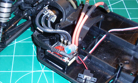
Start by mounting the ESC as shown. Feed the receiver wire through the slots in the chassis and solder the motor wires in place. Also attach the sensor wire and mount the switch. My Tekin RS ESC fits perfectly and, thanks to it’s externally-mounted wires, makes wiring up a cinch.
Step 2
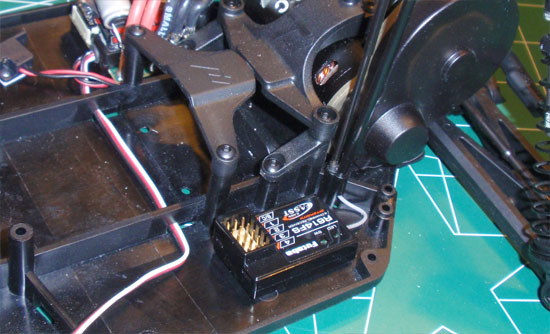
Mount the receiver on the opposite side of the chassis. Feed the antenna wire through the molded antenna mount and into the tube. Slide the tube in place and secure with the set screw.
Step 3
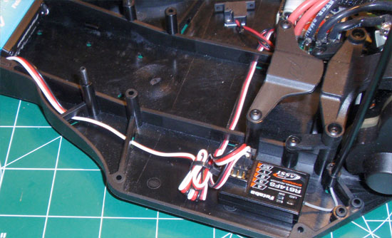
Feed the servo wire through the chassis slots and over to the receiver. Tie both up the servo and ESC leads up and plug into the servo.
Step 4
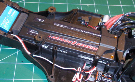
Drop the battery into place, adding the foam spacer in either the front or rear locations. You can cut the foam in half for smaller increments. Slide the battery strap into place and screw the plastic thumbscrews onto the long set screws. Tip: Screw the setscrews in farther so you don’t have screw the thumbscrews down a ton to get it to secure the battery strap. Plug the battery in and check your electronics setup.
Team Durango DEST210R Online Build – Part 12
The final step with the Team Durango DEST201R is the body, wheels and tires. Since they are a good all-around tire at the track I plan to test at, I went with the Proline Suburbs. The body comes with the kit but I sent it out to JGO Paintz (located in Las Vegas) and the guy did it up! Way more bad-ass than I was expecting but certainly looks good in my red/white/black colors. I wish I could retain this guy to do ALL my race bodies like this!
Build Notes:
• You will be gluing the tires to the wheels so I suggest picking up some CompetitionX Gloo Toobs. These will really make your life much easier during the gluing process.
• Tires are 80% of your vehicles setup. Check to see what tires work at your track before mounting anything up.
• To help mount the tires to the wheels, we will be cutting the inside of the foam inserts. This is not really a step but more of a tip; if you choose to keep the inserts full move on to Step 120.
Step 1

The first step for mounting the tires is to cut away part of the foam insert. Take your insert and turn it inside out.
Step 2

With a pair of sharp scissors, but a little bit from the inside ‘corner’ as shown. You don’t need to take much off.
Step 3

Flip your inserts back and stuff them into the tires as shown. Make sure they seat completely within the tire.
Step 4

Push the wheel through and glue into place. Glue one side, let it dry and duplicate with the other side. Again, the CompetitionX Gloo Toobs are excellent at avoiding any kind of gluey mess.
Step 5

Once the tires are completely dry, mount them up to the DEST210R. Make sure the axles-mounted hex is seated in the wheel hex before cranking down on the wheel nut.
Step 6

Attach your front body mounts as shown. They are directional so make sure you have the splined side attaching to the splined mount. TIP: Don’t screw the screws in all the way yet. Press the mounts into place and test fit your body. If it doesn’t fit, you can adjust the mounts without having to take the screws out. Once you get the mounts where you want them, tighten the screws all the way down.
Step 7
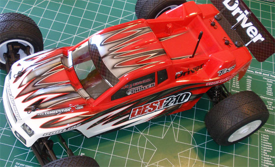
Place the body on and secure with the body clips. Looks sick, right? JGO is the man!
And you’re done! Thanks so much for following along with the step-by-step build of the Team Durango DEST210R.

