

Axial EXO Terra Online Build
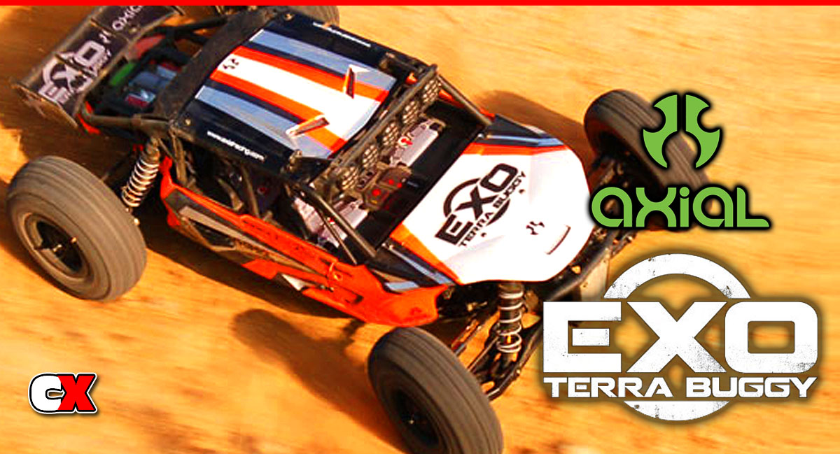
The EXO Terra is Axial’s first attempt at a full blown, semi-race buggy. While being touted as more of a fun vehicle (which it REALLY is!), there will be those that set this sucker out on a track…I know I will be.
Axial EXO Terra Online Build – Part 1
We will be assembling both the front and rear differentials. The build is exactly the same on both so when you’re building one, you can build the other the same way.
Build Notes:
• There are a TON of plastic parts trees that you will need to work with…in no particular order. Make sure you have a large work area.
• In the first step you’ll be working with some diff oil. Keep some paper towels handy to clean up any mess.
• HAVE THE RIGHT TOOLS! I can’t stress enough how crucial it is to have the right equipment to build this car.
Step 1
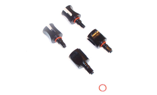
Start off by sliding a red o-ring over all 4 of the outdrives. Slide it all the way down to the base.
Step 2
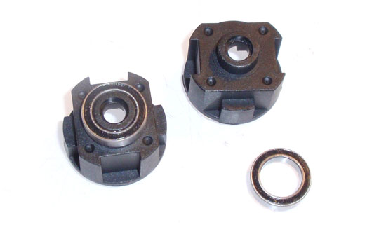
Take the outdrive bearings and pop them into place on the diff housing.
Step 3
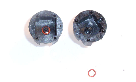
Slide the outdrive through the diff housing, flip the housing over and slide another red o-ring over the outdrive shaft. Work it down as far as it will go.
Step 4
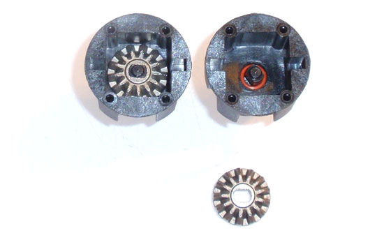
Take the larger sun gear and slide it down over the output shaft. The sun gear and shaft are keyed, so make sure you align the flats before installing.
Step 5
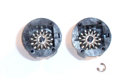
Lock the gear in place with an e-clip. BUILD TIP: This step drove me crazy as it was extremely difficult to get the e-clip into place to snap it in. Place a drop or two of the diff fluid on the top of the shaft/sun gear before dropping the e-clip into place. SO much easier.
Step 6
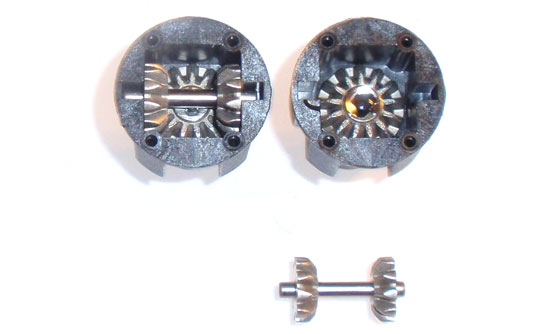
Slide two of the smaller sun gears onto the pin and drop down into the diff housing. Make sure the sun gears are facing each other.
Step 7
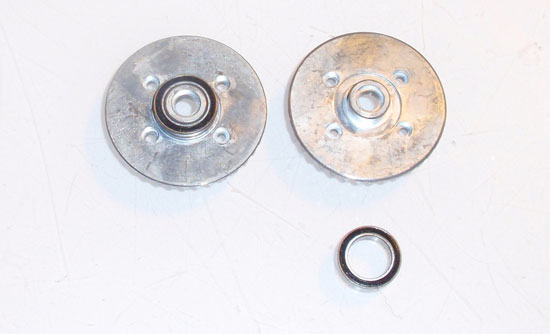
Take the large outdrive bearings and slide them into place over the diff gear as shown.
Step 8
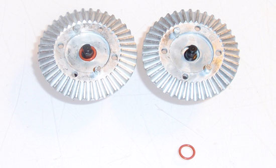
Take the available two outdrives, feed them through the diff gear, flip the diff gear over and attach another red o-ring. Slideit down as far as it will go.
Step 9
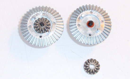
Slide the larger sun gears over the outdrives like you did in an earlier step. Remember, these are keyed and the flats need to be aligned before installing.
Step 10
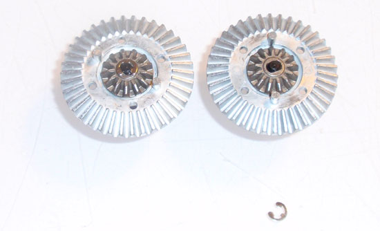
Secure with an e-clip. These e-clips are much easier to get at so you won’t necessarilly need any fluid to hold them in place.
Step 11
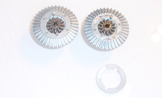
Install the diff gasket as shown.
Step 12
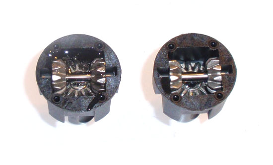
Fill the diff housing up with diff fluid as shown. Rotate the outdrive a few times to make sure the fluid seeps down into the whole housing. Refill if necessary.
Step 13
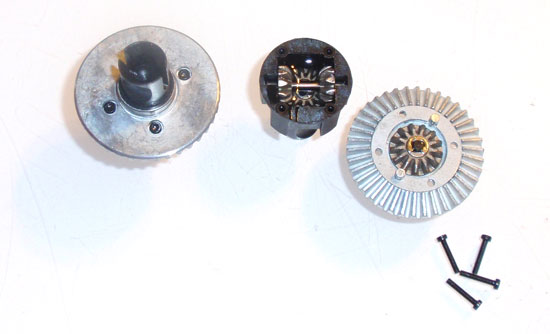
Take your assembled diff gear and attach to the diff housing. The diff gear pins should line up with the slots that the sun gears slid into. Bolt the diff together with the 2x10mm screws.
Step 14
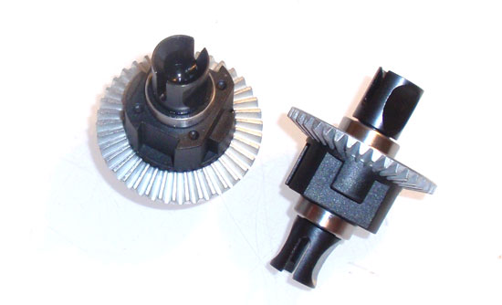
Easy peasy. Set your diffs aside.
Axial EXO Terra Online Build – Part 2
Part 2 of our Axial EXO Terra build revolves around the front gearbox and suspension.
Build Notes:
• Axial uses a combination of fine and coarse pitch screws in the following steps. Pay attention to the lengths and pitch when building.
• The caster and steering blocks are directional. Pay attention to the direction you install them.
Step 1

We start off Part 2 by assembling the gearbox bevel gears. Insert the pin into the input shaft, slide the bevel gear in place and secure with the e-clip. You’ll need to build two of these; one for the front and one for the rear gearboxes.
Step 2

Insert the 2 5x11mm bearings into the gearbox half and slide the bevel gear assembly in place. Make sure the bevel gear is on the inside of the case.
Step 3

Slide the outdrive onto the bevel gear shaft, line up the holes and insert the setscrew to secure. It’s a good idea to put a small dab of loctite on the setscrew.
Step 4

Put a healthy amount of grease on the bevel gear. I used a bit of Team Associated’s white lube for this step. Set one of the gearboxe halves aside. It will be used later for the rear assembly.
Step 5

Insert the completed differential into the gearbox and attach the other gearbox half as shown.
Step 6

Attach the front shock tower to the gearbox. Attach the shock tower brace but notice the orientation of it; this is a directional piece.
Step 7

Pull the steering knuckles and caster blocks off the parts tree and place on a flat surface. Pay attention to the orientation of the pieces in the picture; this is how they are paired up in the rest of this step.
Step 8

Insert the 5x10mm bearing into the front of the knuckle and 10x15mm bearing in the back.
Step 9

Take the steering knuckle and position it onto the caster block. Slide the gold-colored pins in place to secure the two pieces together. Use the setscrews to lock the gold pins in place. Do not overtighten; make sure the steering block rotates freely.
Step 10

Slide the axles through the bearings. The instructions tell you to insert the dogbones too but you’ll soon see it’s a pain to deal with. Don’t insert them yet but do keep them handy.
Step 11

Remove the front suspension arms from the parts trees. Note the orientation of the arms. Now take the steering knuckle assembly and attach it to the suspension arm using the hinge pin. Again, note the orientation. Lock the kingpin in place with the setscrew.
Step 12

Take your F2 block and press the axle bushings into place. Attach the F2 block to the rear of the front gearbox as shown.
Step 13

Feed the long hinge pin through the arm and insert it into the bushing in the rear arm mount. Insert the hinge pin bushings into the front arm mount and place it over the hinge pins, capturing them in place. Secure with the two 3x20mm screws. The #1 bushings have the capture hole offset. Axial doesn’t say which direction these should go so I inserted them with the hole up. This should rake the hinge pins upward for more kick-up.
Step 14

Assemble the turnbuckles. Note the direction of the pivot balls. Axial states 40mm which works well, so stick with that.
Step 15

Insert the dogbones into place and attach the turnbuckles. Again, note the direction of the pivot balls.
Step 16

Wah-lah. You have a completed front gearbox and suspension for the Axial EXO. Set it aside and get ready for the rear end.
Axial EXO Terra Online Build – Part 3
Part 3 revolves around the rear gearbox and suspension. This is a pretty straighforward build.
Build Notes:
• The rear gearbox and suspension is much like the front. The same steps will apply.
Step 1
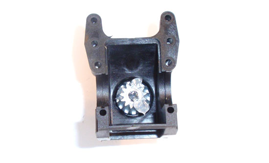
Grab the second gearbox half that you built early on. If you didn’t put any grease on the input gear, do so now.
Step 2
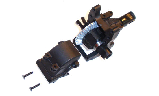
Insert the differential and attach the outer case half. Note the direction of the differential.
Step 3
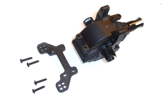
Attach the rear shock tower as shown.
Step 4
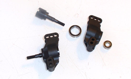
Assemble the two rear uprights by installing the bearings and outdrives. They uprights are the same on both sides so there is no need to worry about a left and a right piece. Don’t worry about attaching the dogbones; they’ll only get in the way. We’ll insert them later.
Step 5
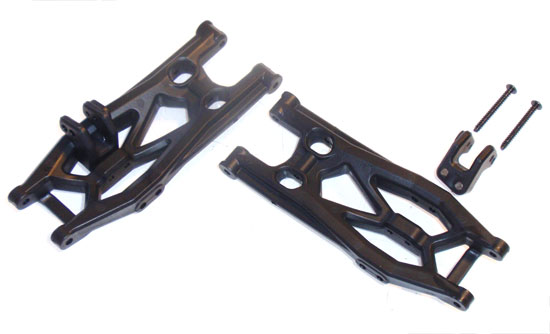
Attach the shock mounts to the rear suspension arms. Note the orientation; the piece should ‘curve’ towards the inside of the arm.
Step 6
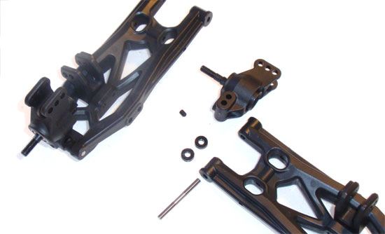
Attach the rear uprights to the suspension arms. Make sure you install the spacers on the opposite side of the arm than the shock mounts.
Step 7
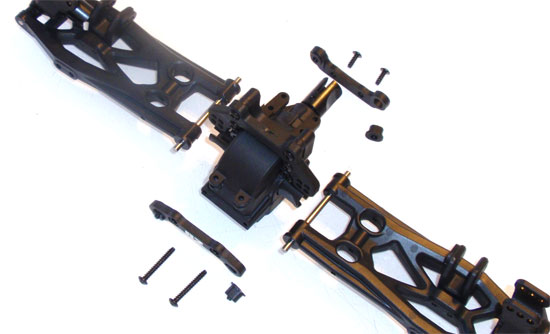
Press the hinge pin inserts into both arm mounts and attach the R2 hinge pin mount to the back of the gearbox. Slide the hinge pins through the arms and insert into the rear hinge pin mount. Align and attach the R1 hinge pin mount to the front of the rear gearbox and secure. Rotate the arms up and down to make sure there is free movement. You don’t want any binding in the suspension arms.
Step 8
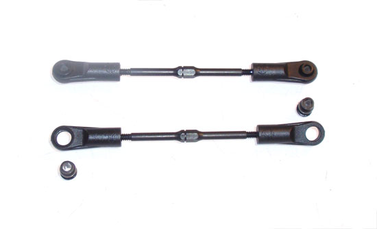
Build a pair of turnbuckles and insert the bushings. Axial’s 48mm setting is spot on.
Step 9
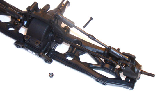
Attach one end of the turnbuckle to the upright. Slide the dogbone into place and attach the other end of the turnbuckle to the rear shock tower. Go ahead and use the attachment locations provided by Axial.
Axial EXO Terra Online Build – Part 4
In part 4, we assemble the center differential. Depending on the power you plan and running through your EXO, you can change this oil to help balance the front/rear drive ratio.
Build Notes:
• The center differential build is much the same as the front and rear diffs. Having some clean towels handy will help with clean up.
Step 1
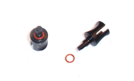
Slide the red o-rings over the outdrives. A dab of diff fluid will help keep them lubed.
Step 2
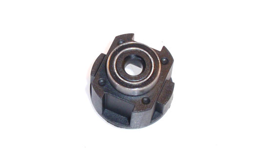
Press the bearing onto the differential housing. It should be a snug fit and should sit flush as shown.
Step 3
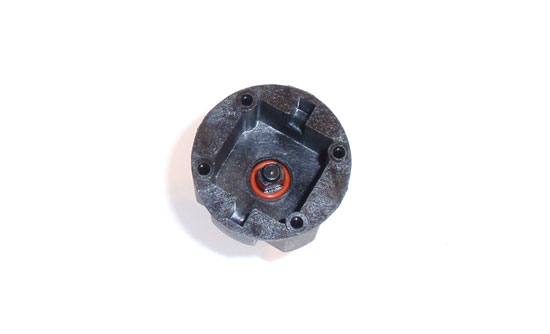
Insert an outdrive through the housing and slide another red o-ring over outdrive.
Step 4
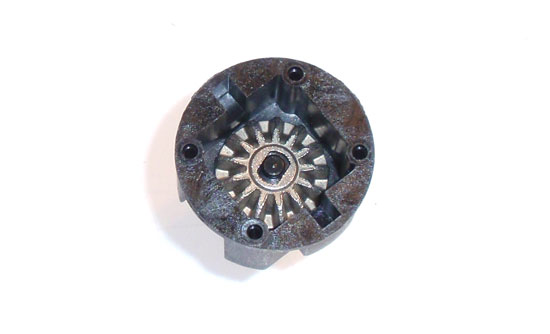
Align the flat spots on the outdrive and spider gear and slide the gear into place.
Step 5
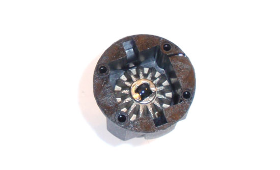
Snap the e-clip into place. As we did with the front and rear diffs, a dab of diff fluid will help keep the e-clip in place while you lock it to the outdrive.
Step 6
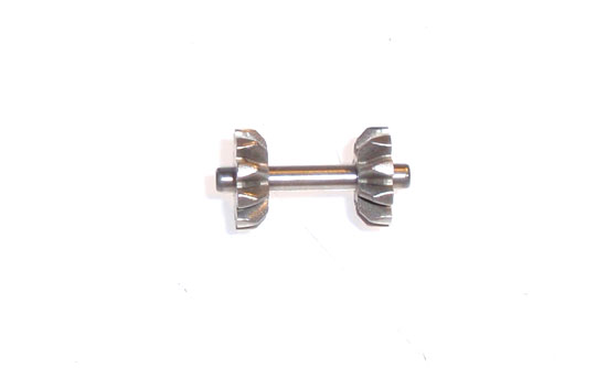
Slide the small spider gears over the input shaft as shown…
Step 7

…and drop it into place within the diff housing. Rotate the outdrive to seat the gears if they don’t push all the way into place.
Step 8
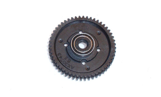
Press the bearing onto the diff gear as shown.
Step 9
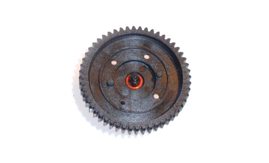
Flip the diff gear over, insert the other outdrive and slide the red o-ring into place.
Step 10
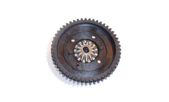
Align the flat spots on the outdrive and spider gear and slide the gear into place.
Step 11
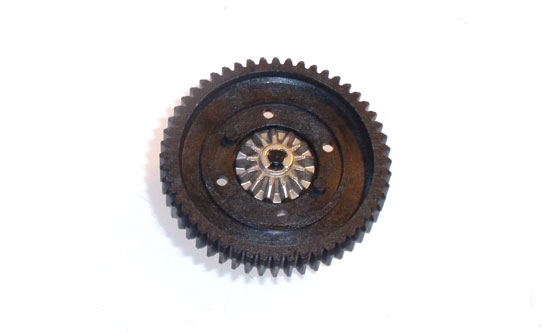
Snap the e-clip into place. This side is much easier to work with so you probably won’t need the diff oil to hold the e-clip in place.
Step 12
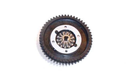
Press the diff gasket into place as shown. If it slides off, a dab of diff fluid on it should help keep it in place.
Step 13
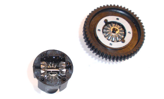
Fill you differential to about 85% with the provided fluid. Rotate the outdrive a couple turns to help circulate the diff fluid thoughout the housing. Let it stand for a minute or so and then refill to about 90% with the fluid.
Step 14
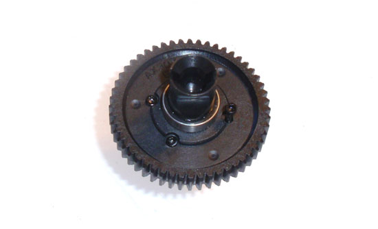
Attach the diff gear to the housing by aligning the pegs in the gear to the slots in the housing. Secure with the four screws.
Axial EXO Terra Online Build – Part 5
This short segment revolves around the assembly of the chassis and plastic side plates. We will also be attaching the center bulkhead and center differential.
Build Notes:
• Have some threadlock ready for the screws that go into the chassis. This will prevent them from backing out when out on the trails.
Step 1
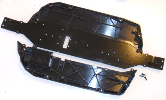
Attach the plastic chassis rails to the main chassis plate. Use a dab of loctite on the screws to prevent them from backing out.
Step 2
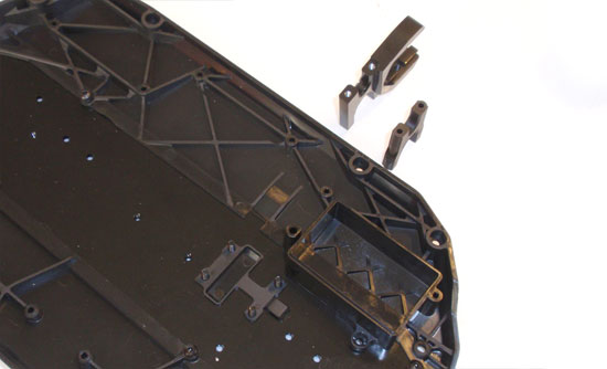
Place the lower plastic gear cover in place and attach both of the center differential bulkhead pieces. Snug the screws up; do not overtighten. Overtightening could twist the bulkheads and cause a mis-alignment of the center differential.
Step 3
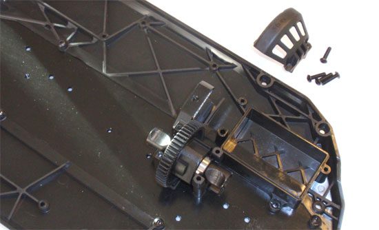
Drop the center differential into place (note the direction). Place the upper gear cover into place and secure with the four screws.
Axial EXO Terra Online Build – Part 6
Part 6 has you assembling and attaching the steering system to your Axial EXO Terra. The EXO comes equipped with a stout servo saver to help protect your servo.
Build Notes:
• Compressing the servo saver spring will help ‘settle’ it quickly. This collapsing of the spring also helps build the servo saver.
• You will need to build two steering rods, however the final assembly of one will be backwards. See the step below for clarification.
• A pair of washers are included with the EXO that are not in the manual. This is an appendum and should be found in your box prior to starting this step.
Step 1
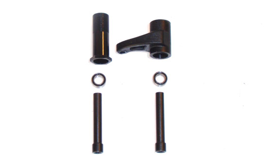
Gently press the bearings into the bottom of the servo bellcrank arms as shown. Note the orientation of the right bellcrank. Insert the steering posts.
Step 2
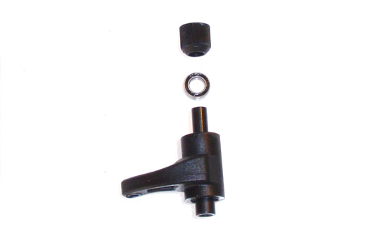
Place a 2nd bearing over the steering post as shown and cap it with the steering post spacer.
Step 3
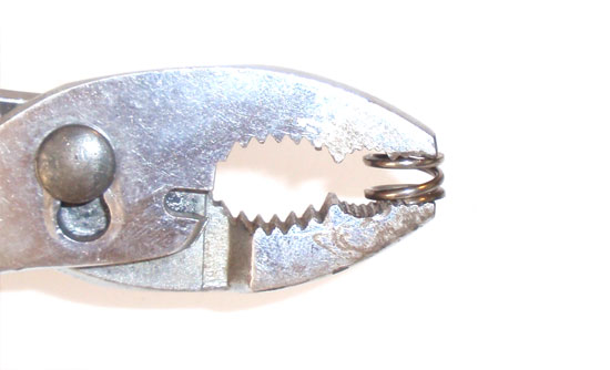
With a pair of large pliers, gently collapse the servo saver spring. DO NOT USE NEEDLENOSE OR ANY OTHER SORT OF SMALL PLIERS! Doing so may skew the spring out of its original position and cause it to not fit over the bellcrank post.
Step 4
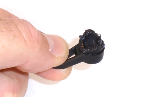
While this is not a required step, it is something I’ve learned to do over the years to most of my offroad vehicles. Carefully coat the servo saver lip with black grease. This will help keep the servo saver lubed when out in the dust and dirt. Not doing so can cause the two plastic pieces to wear out prematurely or even eventually bind up. This is a preventative step that you’ll thank me for later!
Step 5
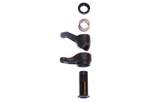
Assemble the servo saver. Note the direction of the plastic pieces. You may also have a little bit of black grease oozing out at this point. Just wipe it clean and you’ll be good to go.
Step 6
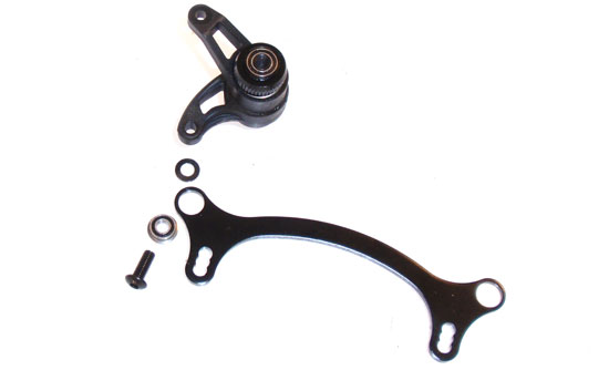
Attach the servo saver bellcrank to the steering rack. The screw and bearing feed through the bottom, then the ‘appendum’ spacer followed by the servo saver assembly.
Step 7
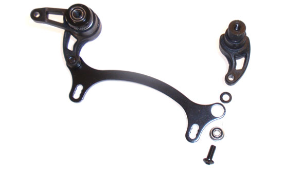
Attach the other bellcrank in the same fashion; screw and bearing through the bottom, followed by the ‘appendum’ spacer and bellcrank. At this point, swivel the steering assembly; it should move freely. If it doesn’t, loosen up the screws feeding through the rack SLIGHTLY and try again. You want free movement with the least amount of slop possible.
Step 8
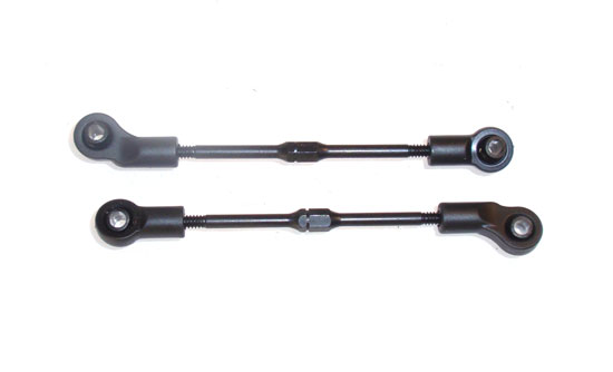
Build 2 steering links as shown.
Step 9
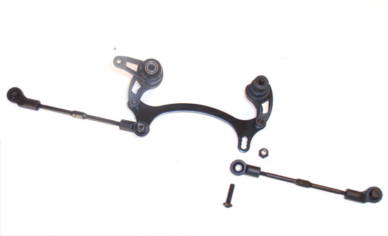
Attach the steering link to the steering rack by feeding the screw through the bottom, through the link and secured with the locknut. Note the direction of the links. I assembled my EXO with the link in the middle hole.
Step 10
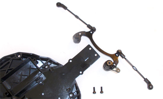
Secure the steering posts to the chassis as shown. A dab of loctite will help prevent these screws from backing out.
Axial EXO Terra Online Build – Part 7
Part 7 has you attaching the front and rear assembled clips to your EXO chassis. This is a fairly straightforward step.
Build Notes:
• Have some thread lock handy for the screws that thread into aluminum parts.
Step 1
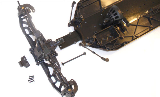
Start this step by inserting the front dogbone into the center diff cup. Line up the front diff cup to the dogbone and insert, holding the front clip to the chassis plate. Insert the two rear-most screws through the chassis to hold the front clip into place (screw in about 1/2 way at this point). Slide the bumper mount into place and thread the other two screws into the gearbox. Tighten them down.
Step 2
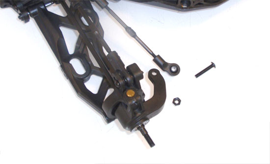
Attach the steering link to the steering block by inserting the screw through the top and down through the steering arm. Secure with the locknut. Complete both sides. Note the orientation of the steering link eyelet.
Step 3
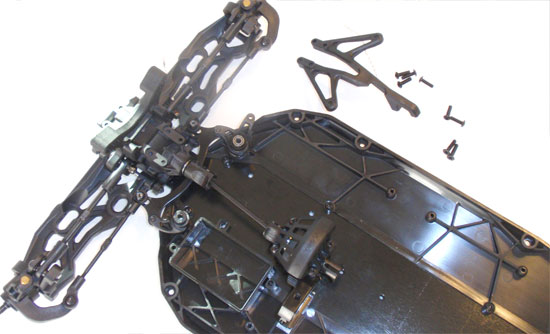
Attach the front chassis brace. Make sure the brace is seated completely before tightening down. A small dab of loctite is required on the screws that feed into the steering posts.
Step 4
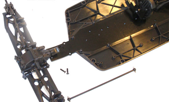
The rear clip attaches much the same as the front. Start by inserting the dogbone into the center diff cup. Line up and insert the dogbone into the rear diff cup and hold the rear clip against the chassis. Secure with the two screws nearest the front of the chassis. Tighten about 1/2 way for now.
Step 5
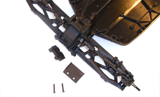
Slide the bumper mount into place, then feed the two screws through the plastic rear chassis guard, through the chassis and into the rear gearbox. Tighten all 4 screws down.
Step 6
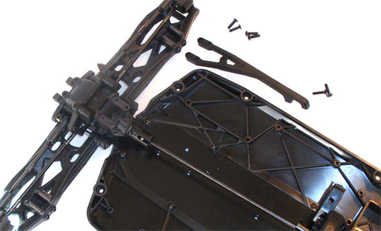
Line up and attach the rear chassis brace. Make sure it is completely seated before tightening.
Axial EXO Terra Online Build – Part 8
Installing the electronics in the EXO does require a little patience. Axial has included plenty of wire tie-downs to make sure none of your wires find their way into the drivetrain, but all this does require a little bit of time to do correctly. Take your time and you won’t have to do major surgery to repair any of it.
Build Notes:
• The EXO can handle quite a bit of power. It can also accept a 540 or 550 size brushless motor! Special pinions will be needed if using a 550 size motor.
• A special mount is included for use with the Novak Havoc ESC. This mount is not required with other ESCs.
• While the receiver mounts in a water-resistant case, I chose to install Axial’s NVS lighting system in the same box. Doing this required the removal of the receiver box top, making my EXO non-water-resistant. I can deal with that for the absolute killer look the EXO now has.
Step 1
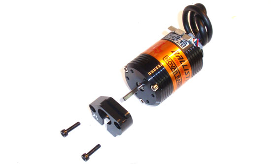
The first step is to attach your motor to the aluminum motor mount. Simple and straightforward, but note that the wire tabs on the motor should be facing up.
Step 2
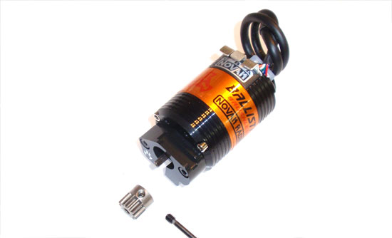
Next, attach your pinion gear. A dab of loctite is suggested on the set screw. The slot at the bottom of the motor mount will allow you to feed the pinion deep into the mount and still tighten the set screw.
Step 3
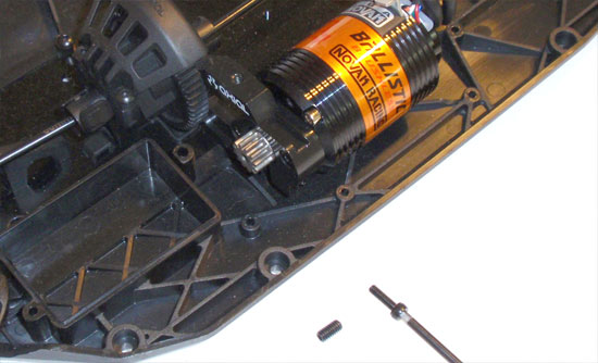
Slide the motor and mount into the chassis mounted motor mount. Screw the adjustment screw and set screw into the mount as shown. Do not tighten yet.
Step 4
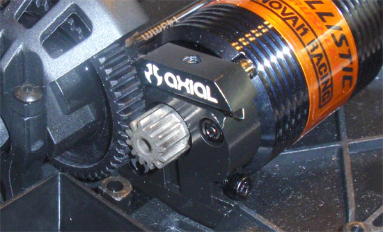
This close-up shows the lower adjustment screw and the upper set screw. By tightening the lower adjustment screw, you will widen the gear mesh between the pinion and spur. Loosening this screw will tighten the gear mesh. Set this screw so there is a very slight backlash between these two gears. Once you are happy with the mesh, tighten down the upper set screw. It does not say this in the manual, but I would suggest a DAB of loctite on these two screws to keep them from backing out.
Step 5
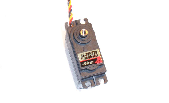
For steering purposes, I’m going with Hitec HS-7955TG Titanium Geared servo. This servo has a monster 333oz of torque; perfect for the heavy duty driving this bad boy is about to endure!
Step 6
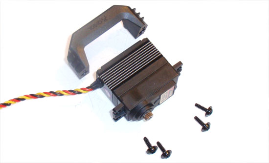
Attach the servo to the servo mount as shown.
Step 7
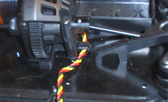
Before installing the servo to the chassis, feed the servo lead through the wire-capture-tab next to the front chassis brace as shown. This can be a bit tricky once the servo is installed.
Step 8
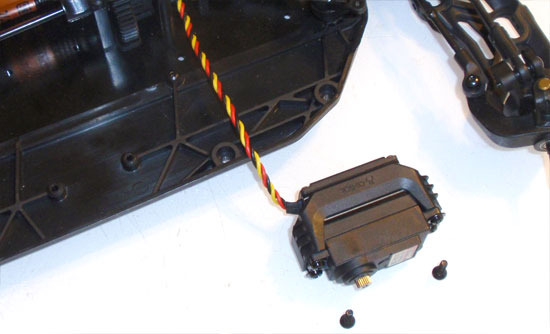
Attach the servo and mount to the chassis.
Step 9
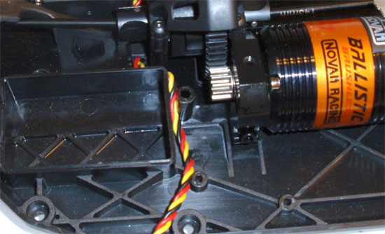
Press the servo lead into the wire-slots located next to the receiver box. This is important!!!! It helps keep the wire away from the central gears.
Step 10
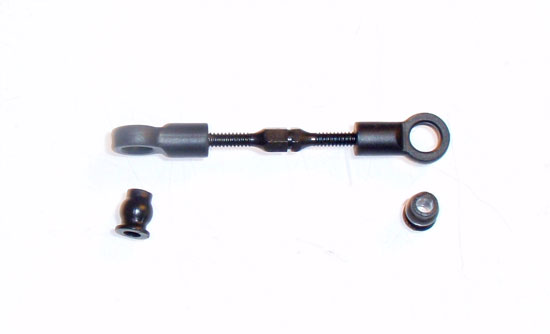
Build the steering link. Axial’s recommendation of 25mm is spot on.
Step 11
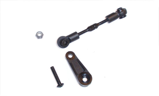
Choose the correct servo arm for your servo and attach one end of the link to it.
Step 12
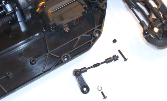
Attach the servo arm to the servo and connect the other end of the steering link to the steering bellcrank.
Step 13
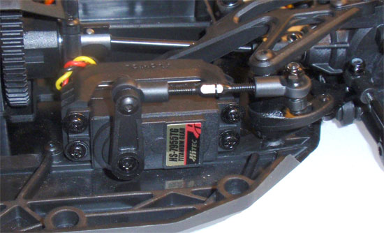
Your assembly should look like this.
Step 14
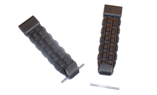
Feed the pin through the rubber battery strap. The straps are a VERY rubbery, well, rubber, and will take a little coaxing to get them through.
Step 15
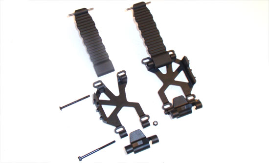
Build a pair of battery holddowns. The battery straps have 3 holes in them for different size batteries. I started with the middle hole. Note the direction of the pieces.
Step 16
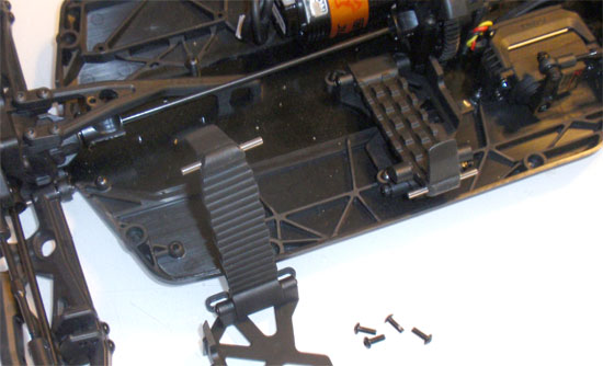
Attach the battery straps to the chassis. At this time it is also a good idea to test fit the battery you will be using. Mine was a bit to big, so I had to rebuild my battery holddowns and use the lower hole. You don’t want to do this step after you’ve completed the EXO. Trust me.
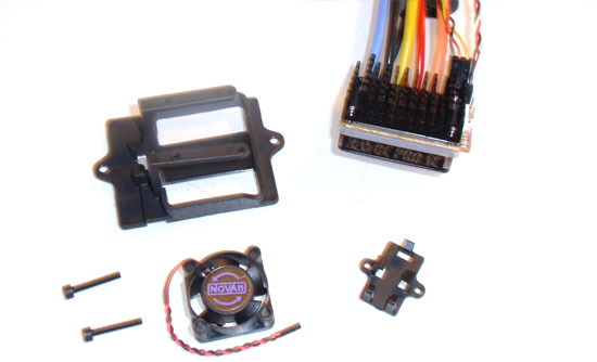
Step 17
Oddly enough, I will be using Novak’s Havoc ESC. I didn’t know that this ESC had it’s own special mount! This makes it easy as pie to install!
Step 18
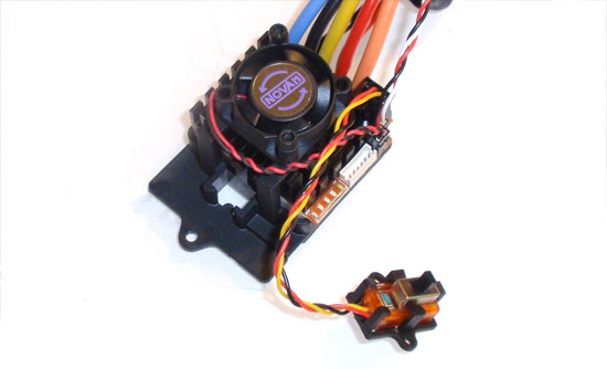
Attach the fan to the top of the ESC, the ESC to the mount and the switch to it’s separate mount. No tape required!
Step 19
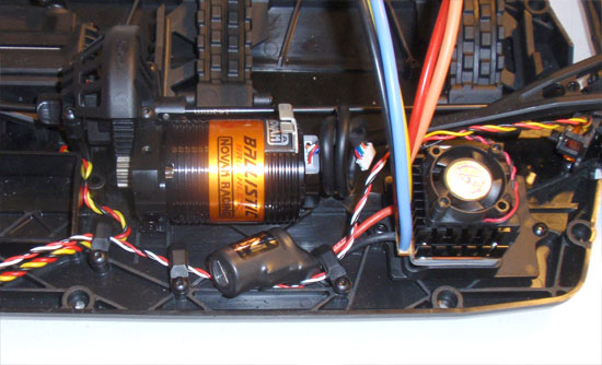
The ESC mount lines up with a pair of holes. Boom, done. Feed the wires from the ESC through the chassis mounted wire-ties.
Step 20
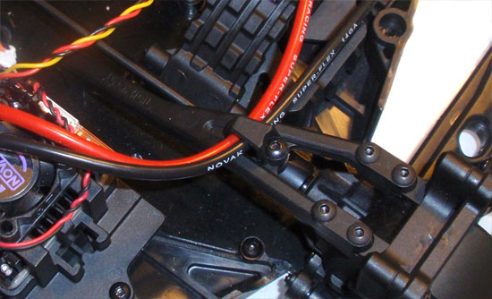
Axial has also added another slick wire-tie on the rear chassis mount. Route your power wires from the ESC through here.
Step 21
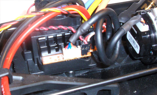
Connect the sensor wire to the ESC.
Step 22
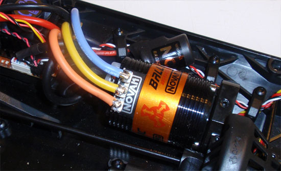
Solder the wires onto your motor. Remember, A goes to A, B to B and C to C. Mixing these up will result in your car going backwards. Really fast.
Step 23

Even though my setup is a little different, I am showing you this step. Fit the rubber grommet over the receiver box. It might be a bit of a pain so a little bit of grease on the corners will help keep it in place.
Step 24
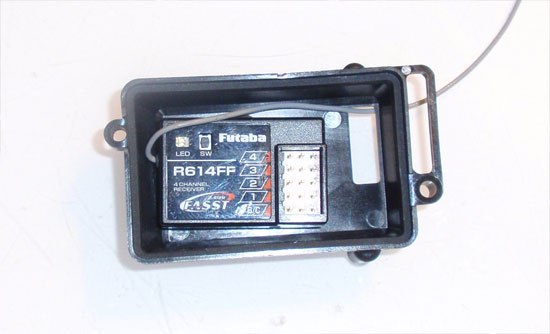
Tape the receiver to the lid of the receiver box. Feed the wires through the lid and plug into the receiver. Attach the water-resistant foam and cap and install to the receiver box.
Step 25
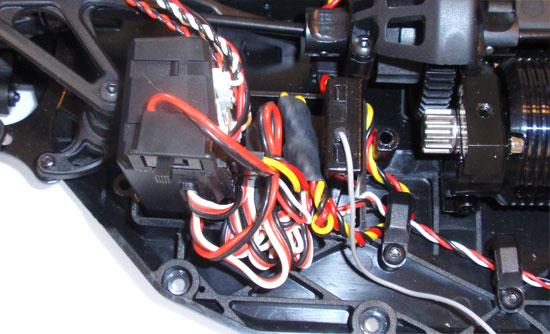
I added the NVS to the receiver box as shown. Yes, the wires are a bit of a mess right now but that will soon be fixed. This is mainly to show how the NVS was installed.
Step 26
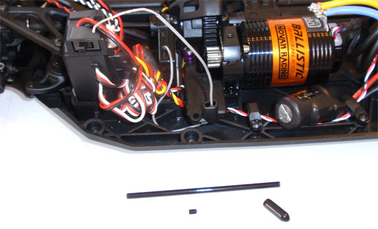
Feed the receiver antenna through the hole and slide up the antenna tube. Press the antenna tube into the hole and secure with the set screw.
Axial EXO Terra Online Build – Part 9
The cage of the EXO is probably the coolest part of this build. It’s rigid build helps protect the EXO’s innards from damage and, with the help of the body panels, also keeps dirt and debris out of the chassis.
Build Notes:
• The EXO’s cage ties directly into the chassis to form a very rigid platform. Do not tighten all the screws down until the entire cage is complete. This ensures the cage is ‘square’.
Step 1
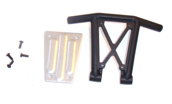
Attach the front aluminum skid plate to the front bumper.
Step 2
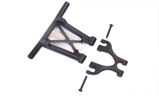
Attach the front bumper to the upper bumper support.
Step 3
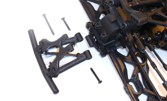
Attach the front bumper (and upper support) the the front bulkhead.
Step 4
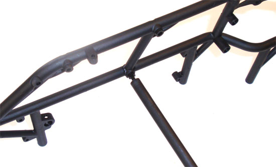
Attach the crossbar to the left side of the cage.
Step 5
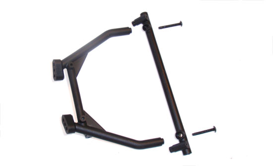
Attach the crossbrace to the cage’s front hood piece.
Step 6
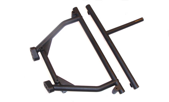
Press the crossbar/chassis mount into the front hood assmebly…
Step 7
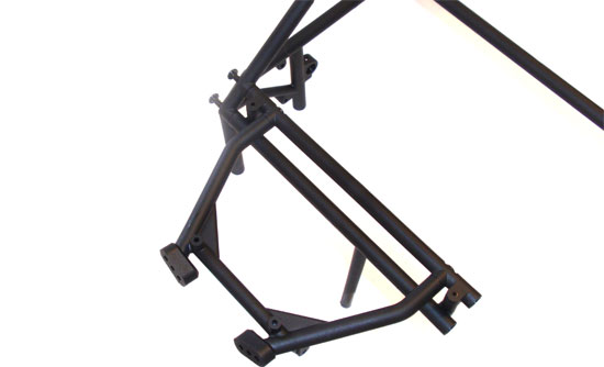
…and attach to the left side of the cage.
Step 8
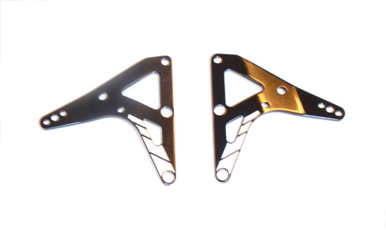
Close up of the aluminum shock mount braces. Note the direction and the white colored boxes. These help designate which side of the chassis they mount to.
Step 9
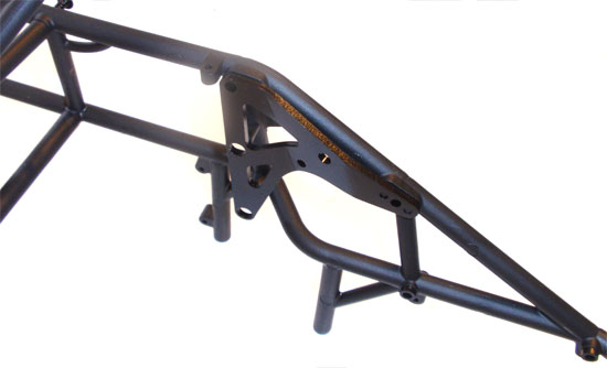
Press fit the aluminum shock mount to the left side of the cage as shown.
Step 10
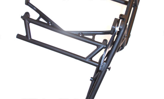
Screw in the rear crossbrace to the left side cage, through the aluminum shock mount.
Step 11
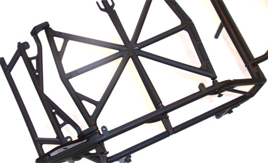
Attach the roll cage top to the left side of the cage. Note the direction of the top cage. Make sure it is facing the right direction.
Step 12
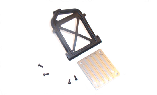
Attach the aluminum skid to the rear bumper.
Step 13
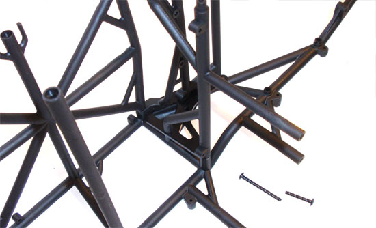
Attach the rear intermediate crossbrace/chassis mount to the left side of the chassis.
Step 14
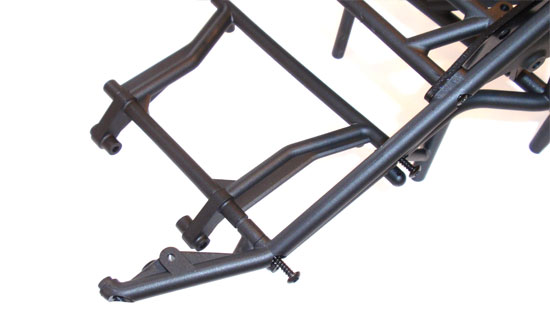
Attach the rear crossbrace to the left side of the cage. Note the orientation of this brace.
Step 15
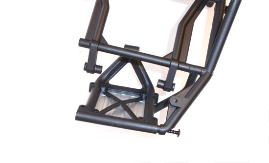
Attach the rear bumper/skid plate to the left side of the cage.
Step 16
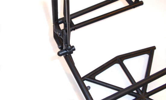
Insert the body mount and secure with the long set screw.
Step 17
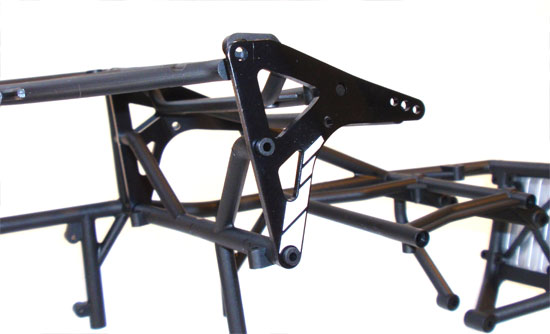
Press the other aluminum shock mount brace into place.
Step 18
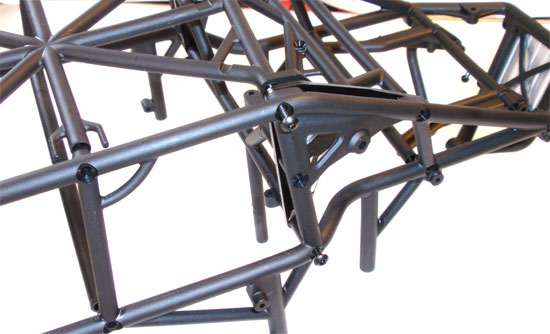
Slide the left hand cage into place and secure.
Step 19
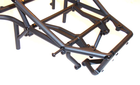
Bolt up the front and rear of the cage. Place the cage on a flat surface (to square it up) and tighten down all of the screws.
Axial EXO Terra Online Build – Part 10
The shocks on the EXO are the same tried-and-true units that come with most of Axial’s crawler line-up. They’re durable and are pretty smooth, so they’re a great addition to the EXO.
Build Notes:
• In this step you will be dealing with shocks oils. Things could get messy so it’s advised to have some clean towels handy.
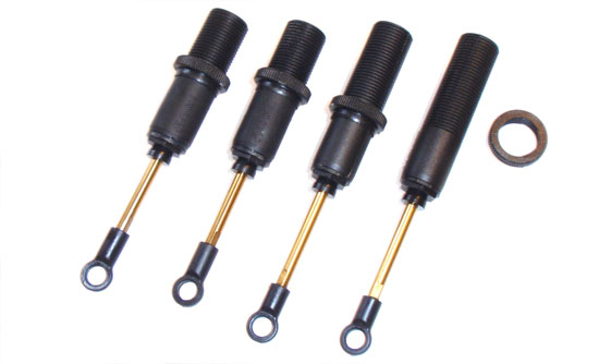
• The front shock bodies and shafts are short, the rears are longer. Pay close attention that you put the shorter shock shaft with the short shock body.
• During the building process, you will need to remove all of the air bubbles out of the shocks. I recommend a high-quality shock building stand like the one from Team Fast Eddy. While this one might be a bit overkill (there are cheaper plastic ones available, I prefer this on because it accepts all different types of shocks…from 1/10th up through 1/5th.
Step 1
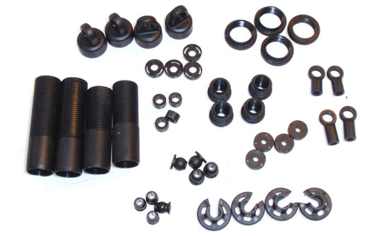
To make the entire shock-building process a little smoother, start off by removing all of the plastic shock parts from the parts trees. Don’t forget to remove any burrs or flashing prior to assembly.
Step 2
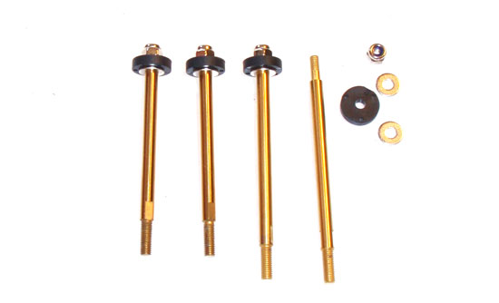
Assemble the 4 shocks shafts as shown. Don’t forget to include the washer on top and below the piston.
Step 3
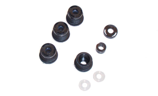
Build the bottom shock cartridges.
Step 4
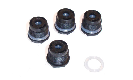
Slide the larger, clear o-ring over the cartridge. This will help seal the bottom of the shocks.
Step 5
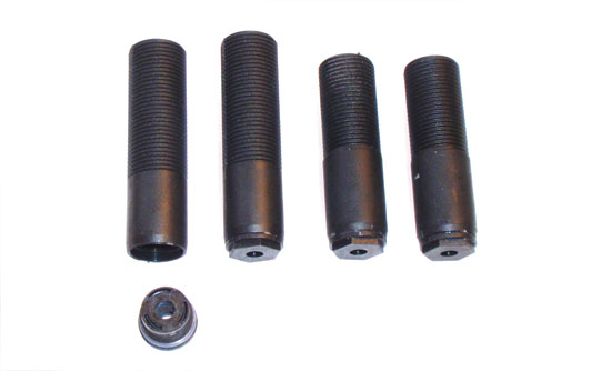
SLOWLY thread the cartridge into the bottom of the shock body until you are 100% sure the cartridge is going in straight; then tighten down.
Step 6
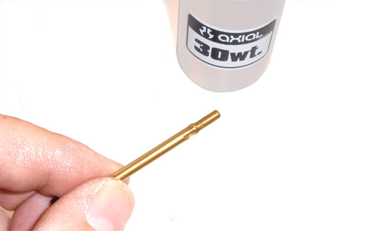
Put a drop of shock oil onto the threads of the shock shaft…
Step 7
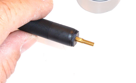
…and carefully slide it into the shock body and through the cartridge. Make sure the short front shafts go into the short front shock bodies and the longer shock shafts into the longer rear shock bodies.
Step 8
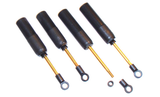
Once through, slide the shaft up and down a few times to lubricate it. Then install the rubber up-stop (note the direction) and the shaft eyelet. Once completed, measure the distance from the bottom of the shock body to the top of the shaft eyelet. The two front measurements should be the same. Tighten or loosen the eyelets until they are. Do the same for the rear shocks.
Step 9
Thread the ride height adjustment screw onto the body. I like to thread mine to the bottom to help keep it away from any shock oil that might pour over in the next couple of steps.
Step 10
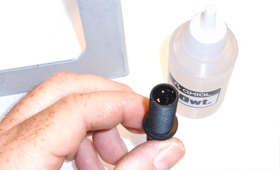
Fill the shock to the top with oil. Slide the shock shaft SLOWLY up and down to help fill the shock below the piston. You should notice the oil level drop.
Step 11
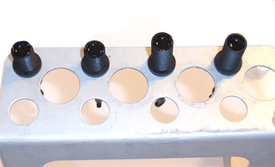
Fill to the point shown in the picture (more is better than not enough) and place your shocks into your shock stand. Here is where you’ll wait about 5 minutes for any bubbles to disperse. Go get a cold drink or some cookies.
Step 12
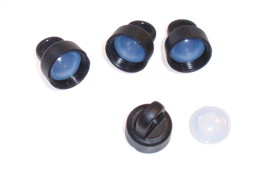
Ok, snack time over? Good. Let’s get back to it. Insert the clear bladder up into the shock cap as shown. It might take a little pursuading but you’ll want it to seat as far up in the cap as possible. DO NOT puncture the bladder!
Step 13
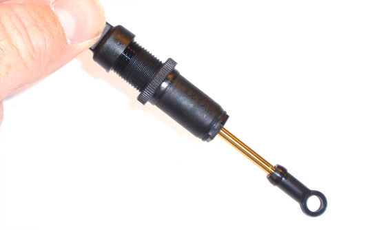
Place the cap on the shock, tilt the shock to about a 45 degree angle and start slowing screwing the cap on. Oil might/should drip out a bit. This is expected.
Step 14
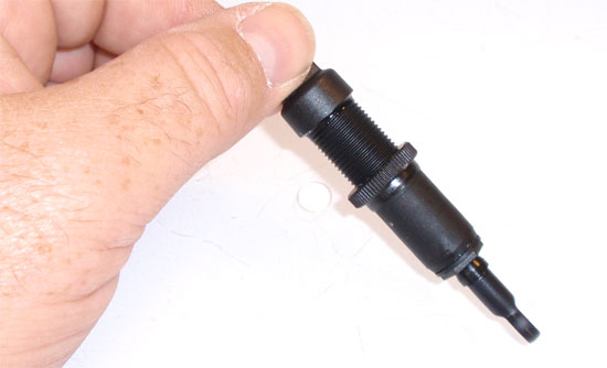
When the cap is about 1/4 of the way on, push the shaft up into the body. More oil might drip out (depends on how full you filled it). Screw the cap all the way on at this point. Pull the shaft out all the way and press it back to the top. You should have about 5-10mm of rebound. Follow the same steps for the other front (or rear) shock. You want the rebound to be about the same. If it’s less, you can add a tiny bit of oil to the ‘less-rebound’ shock or re-bleed the ‘more-rebound’ shock. Get them as close as possible. Follow the same steps with the rear (or front) shocks.
Step 15
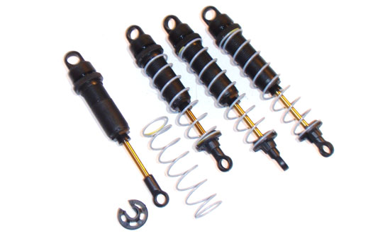
Insert the short springs on the front shocks and the long springs on the rear shocks. Capture the spring with the spring cup as shown.
Step 16
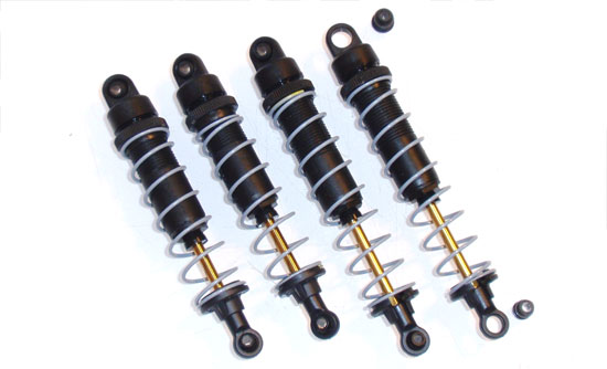
Press the eyelet balls into the shock caps and shaft eyelets as shown.
Step 17
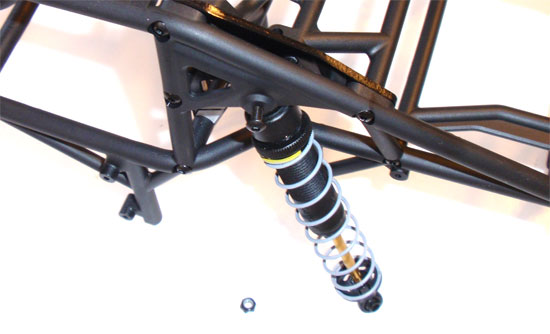
Set the front shocks aside (those will be attached in the next chapter). Take one of your rear shocks and slide the cap in between the EXO cage and the aluminum shock mount bracket. Slide one of the 3x18mm screws through the assembly and secure it with the locknut. Follow theses step for the other side.
Axial EXO Terra Online Build – Part 11
The final installment in the EXO Terra build is the body, wheels and tires. This is the step that brings the whole EXO together.
Build Notes:
• At this point of the build you will have hopefully painted the body panels and interior of your EXO. If not, ya better get on that now!
• I installed Axial’s NVS lighting system. While this is a bit more work, I’m not going to show you the walkthru here. There are probably a couple different ways to install them. We’ll leave that for another time.
• Make sure that you have your EXO chassis nice and tidy…the way you want it. Once the EXO cage is on, it’s not easy to get the chassis without completely removing the cage.
• You will need to open up the body panel mounting holes. You can use a body reamer, dremel, hobby knife or whatever tool you are comfortable with. NOTE! The screws that hold the panels in place are teeny-tiny. Don’t overenlarge the holes or you’ll never get them to mount correctly!
• Don’t forget to pick up your CompetitionX Gloo Toobs for that precise glue job. Yes, they’re the bees knees.
• Thanks to Dave over at RC Paint Labs for the killer paint work.
Step 1
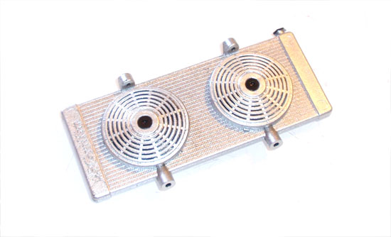
Axial has teamed up with Griffin Radiators to mold a realistic-looking, kind-of functional radiator. By kind-of I mean the blade turns. I can see a cool project here to make it actually functional. Anyway, build your radiator as shown. I painted mine silver to help make it stand out in the back of the cage area.
Step 2
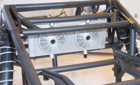
Install it from the top using the two 2.6x8mm screws. Looks pretty cool painted up. You can even see the Griffin logo.
Step 3
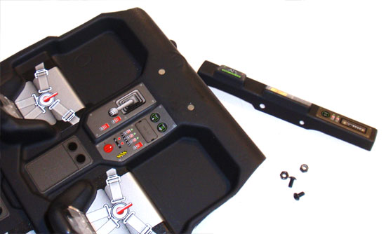
The next step was to assemble and install the rear deck-lid light bar. If you are not using lights, go ahead and do this now. If you are using lights, you might want to wait until later when the cage is attached to wire them up correctly. Make up your mind and then sticker up and assemble the EXO interior. Mine was painted flat black from the top-side to give it a little bit more realistic look.
Step 4
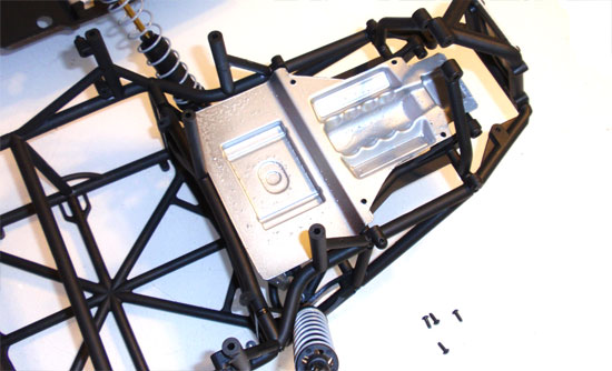
Open the mounting holes, sticker up the rear deck/motor area and attach to the rear section of the EXO cage.
Step 5
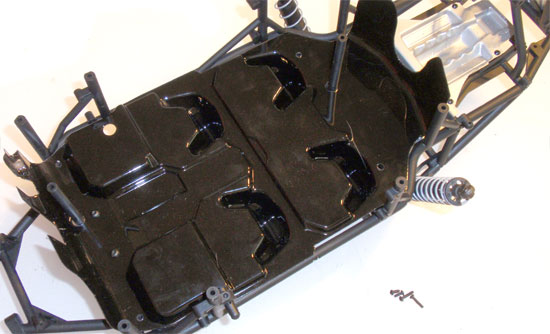
Open the mounting holes in the interior section and mount to the EXO cage.
Step 6
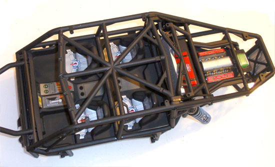
Flip it over and *BOOM*, DIALED. If yours doesn’t look like this, you did something wrong.
Step 7
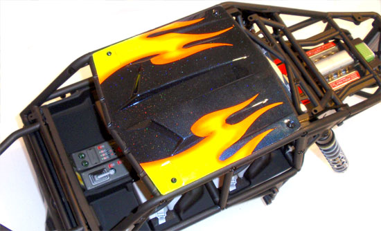
Open the mounting holes and attach the roof panel to the EXO cage.
Step 8
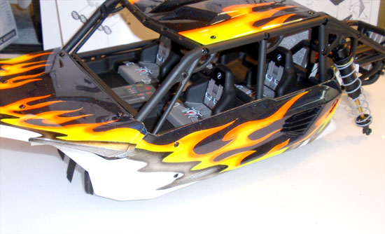
Open the mounting holes and attach the nose piece to the EXO cage. You can also mount the left side body panel. Don’t forget to add the cool plastic faux intake panel. Nice little extra detail.
Step 9
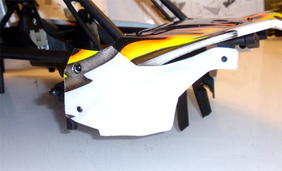
Rotate the EXO cage, open the mounting holes and attach the front right body panel.
Step 10
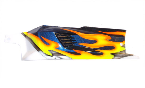
Take your right side body panel/battery panel, open the holes and attach the other plastic faux intake piece.
Step 11
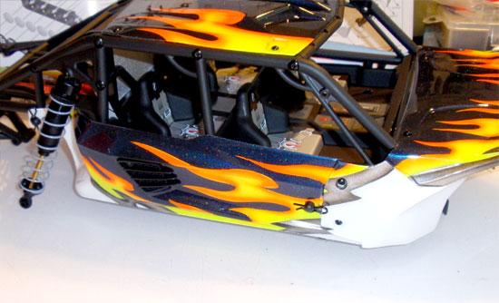
Line up the body panel and attach with body clips.
Step 12
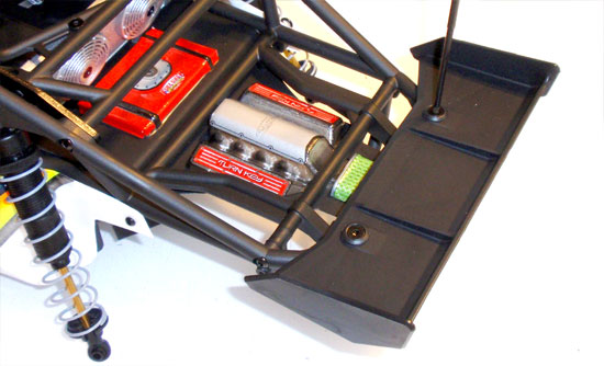
Attach the rear wing.
Step 13
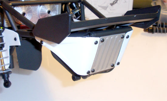
Open the holes and attach the rearmost body panels. These are directional so make sure you install them on the correct side.
Step 14
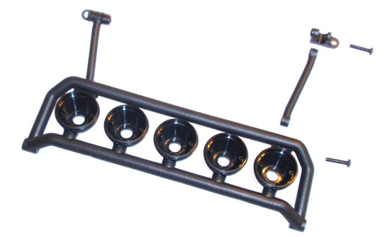
Assemble the top light-bar legs…
Step 15
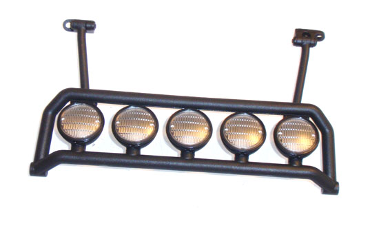
…and press in the plastic lenses. They should snap into place.
Step 16
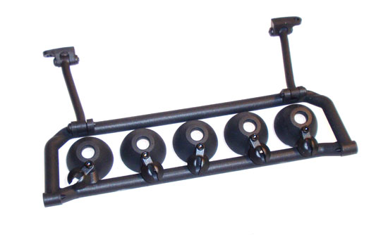
Attach the LED holders. If you are not installing lights, you could skip this step.
Step 17

Install the LED holders on the rear-deck light bar.
Step 18
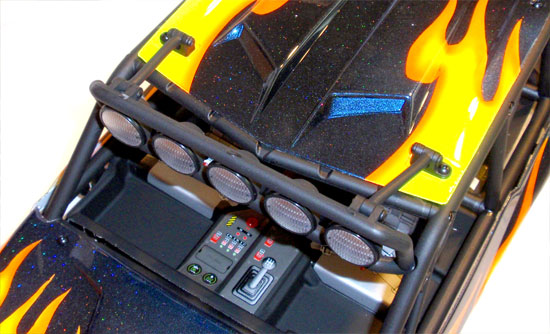
Attach the front lightbar as shown. You will need to remove and replace the front two roof-panel screws. You can mount the rear light-bar at this time also.
Step 19
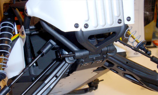
Fit the EXO cage onto the chassis. You might need to do a little massaging to get it to line up just right. Screw it to the chassis per the instructions and attach the 3x20mm screw through the rear bumper.
Step 20
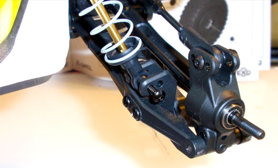
Swing the rear shocks into place and secure with the 3x15mm screws.
Step 21
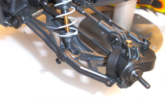
Take one of your completed front shocks, line up the shock shaft eyelet with the outside hole in the front arm and screw into place. Do the same thing for the other side.
Step 22
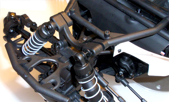
Attach the top of the shocks to the front shock tower with the 3x25mm screw. This screw also ties into the front of the EXO cage to make a seriously rigid platform! Don’t forget the little washer behind the top of the shock.
Step 23
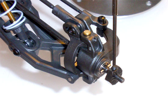
Insert the wheel pins into the axle, slide the wheel hexes over them (line up the slot and the pin) and secure with the setscrew. A little drop of loctite here will help keep that setscrew into place.
Step 24
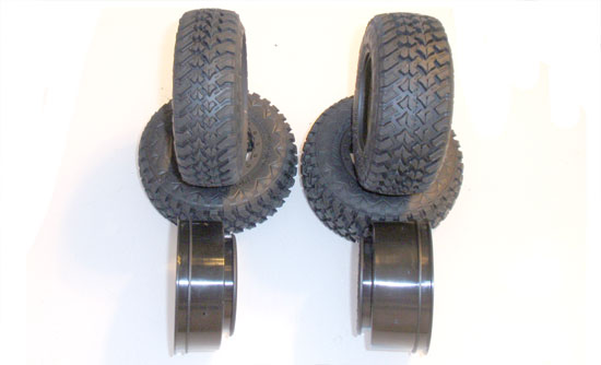
Hang in there…almost done! As you can see from this picture, there are narrow and wide wheels and tires. The narrow ones go on the front, the wide ones on the rear. And yes, these are officially licensed Hankook DynaPro MT tires!
Step 25
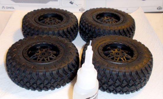
Fit the tires over the wheels (don’t forget the inserts) and work them until all the tires sit in the ‘bead’ of the wheel. Using your CA glue (and, hopefully some CompetitionX Gloo Toobs), put a small, consistent bead of glue around the entire front/rear wheel/tire combo. The Gloo Toobs will definitely help keep mess to a minimum.
Step 26
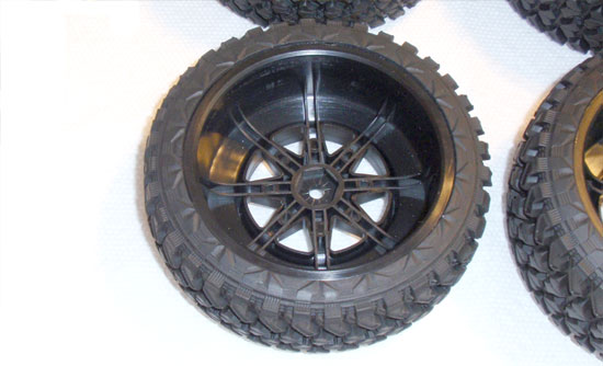
Flip over and glue the opposite side. See any glue? RIGHT!!!! Thanks CompetitionX Gloo Toobs!!!
Step 27
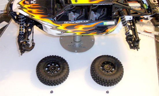
Once the glue has dried (give it about 15 minutes per side), you can mount the wheels and tires to your EXO. Remember, narrow set on the front, wide set on the rear.
AND YOU ARE DONE! Time to go out and have some serious fun! Thanks for following along with CompetitionX’s Axial EXO Terra build. If you liked this, please click the ‘LIKE’ button or, better yet, tell a friend!
Thanks.

