
Element Enduro Sendero Online Build
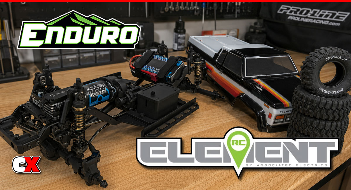
The rumor of a trail truck from Team Associated was strong, however what surprised the world was that it was released under a new brand name – Element RC. Not only was the brand something out of the blue, the truck itself surpassed what everyone was expecting from the race-bred company.
The Element RC Enduro is a top-notch truck that is chock full of high-end features; ladder-frame chassis, CMS (Chassis-Mounted Steering), aluminum shocks, Stealth-X transmission (with an overdrive feature) and all of the molded parts poured from AE’s competition-grade plastics. It’s handling it amazing as well – at the last Pro-Line By The Fire event, the Element RC crew had quite a few Enduros out on the trails and let people, at random, take them through a few gates. Fantastic marketing, but also let perspective buyers get a feel for the truck out in its element (see what I did there?).
Soon after the release of the RTR, Element RC announced a kit version. This is the exact same truck as the RTR minus the body, wheels, tires, bumpers and electronics – you get to choose all those goodies yourself to completely customize your ride.
This article will take you through the entire build process minus the body, wheels and tires. I have an idea of what I want to do, just not sure about it yet – that’s for another article.
Element Enduro Sendero Online Build – Part 1
If you’re like me, you’re ready to dive head-first into the build of the Element RC Enduro Builder’s Kit. If you’re REALLY like me, you’ll probably just want to tear into Bag 1 and just go at it.
I would suggest, however, a little patience up front to get acquainted with the manual and the parts included. Not only has Element RC done a great job with packaging, they’ve also added some fun touches to the manual; ie, each Step has been typecast as a Gate, so Step 1 is Gate 01, Step 2 Gate 02, etc. It’s fun little details like this that show how much thought really went into this rig!
Ok, enough talk – let’s get building!
Build Notes:
• Before you start your build, I would suggest giving the manual a quick read. This will help you familiarize yourself with how the legend works (screw sizes) as well as where they go. Some build steps use screws that look the same (drawings) but are actually different lengths. Just double check any screw lengths prior to installing.
Step 1:
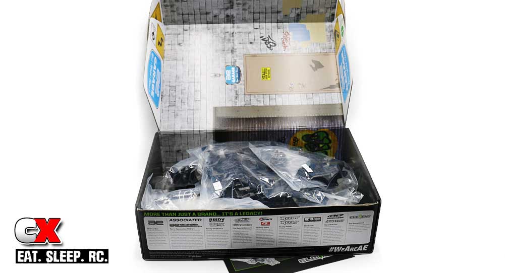
Upon opening the box, you’ll see the standard poly bags filled with all the build parts for the Enduro kit. You’ll be happy to know that one of the coolest parts of this truck, the faux garage scene printed on the INSIDE of the RTR box, is also included with the Builder’s Kit. While not quite as big, it will still act as a great base setting for many photos.
Step 2:
The Builder’s Kit instruction manual is quite good. There were a few minor issues I had throughout the build (some Element RC related, some due to my anxiousness to get the kit done) and I’ll call out these during the build when needed.
Step 3:
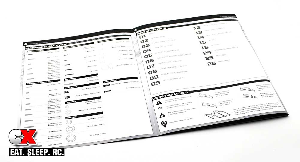
As with most of the current AE manuals (and I’m sure future Element RC guides), a 1:1 hardware legend is included in the front cover. Keep this flap open during the build to match up your screws – makes it easy peasy.
Alrighty, now that we have some general knowledge of what comes in the box, let’s get to the build. Up first – Part 1 – the main chassis!
Element Enduro Sendero Online Build – Part 1
Like almost every other trail truck on the market, the Enduro is built on a dual ladder-frame chassis. Multiple cross-braces ties the two sides together to form a strong platform for the rest of the truck.
Build Notes:
• There are a few things to watch out for during this step; screw lengths appear to be the same (in pictures) however they may not be – not all are called out. Double check each length (and location) prior to installation.
• Other than the actual photo, the shock hoops aren’t specifically designated. Pay close attention to these during installation as well.
Step 1:
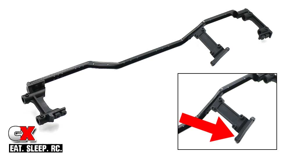
The first step is to install the front and rear bumper mounts as well as the battery mount. Pretty simple step, but pay close attention to the orientation of the battery mount (see inset).
Step 2:
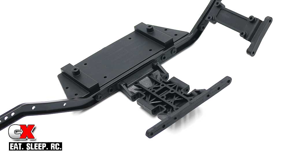
Install the left-side floorboard and gearbox mount. The gearbox mount can be installed in either direction.
You will, however, want to pay close attention to the screw lengths and install holes here.
Step 3:
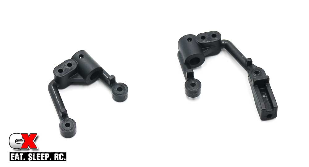
Shock hoops. These are the left side hoops with one having the panhard link mount. Note that 3x12mm screws are used to attach both the front and rear shock hoops.
Step 4:
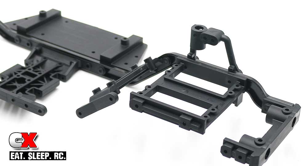
Attach the front shock hoop to the servo tray. The tray is directional; note the spacing of the mounts on the side of the tray.
Step 5:
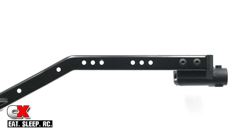
Before mounting the rear shock hoops, I wanted to point out the multiple holes in the chassis for different wheelbase lengths. Of the three holes, the front are for 11.8″ (299mm) wheelbase, the middle for 12.0″ (305mm) wheelbase and the back for 12.3″ (313mm) wheelbase builds. This will help keep the angle of the shocks straight up and down, however you can experiment with the mounting locations to suit different handling (ie, axle at 12.3″, shock hoops mounted in 12.0″).
Step 6:
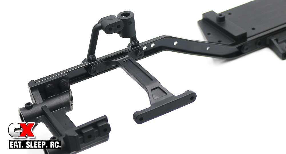
I’m building my Enduro with the hoops at the 12.3″ wheelbase. You will also be attaching the rear chassis brace.
Step 7:
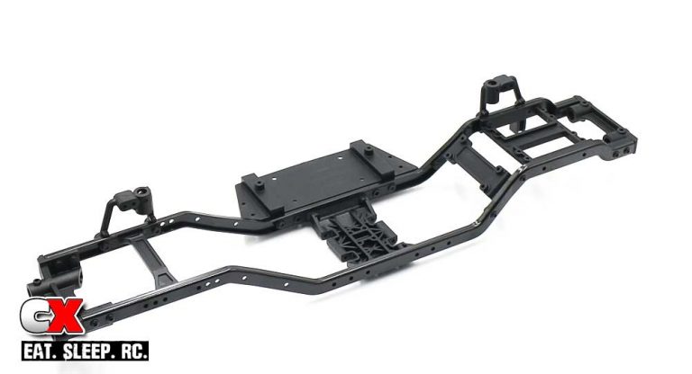
Attach the right side frame rail using screws for the front bumper mount, battery tray and rear bumper mount.
Step 8:
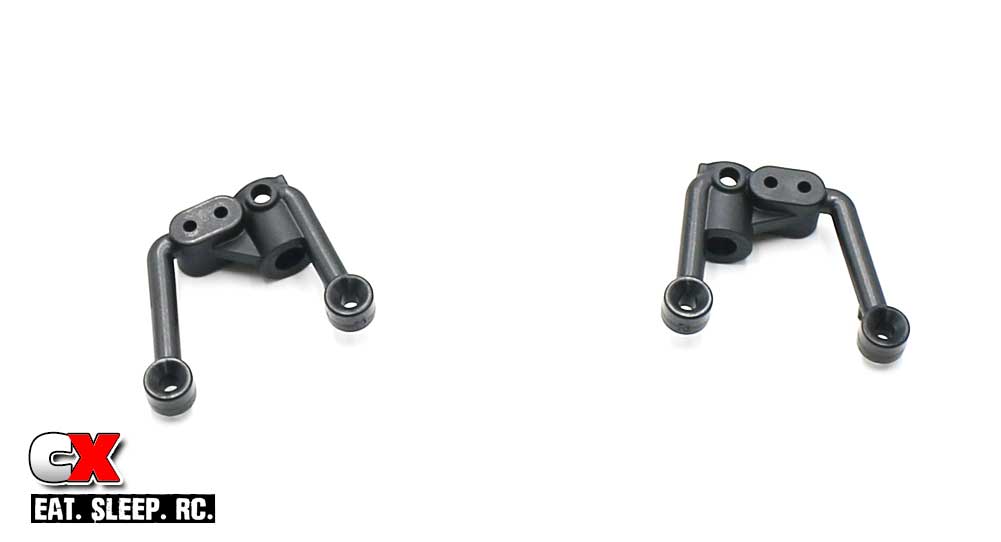
A quick look at the shock hoops from the right side of the truck – for orientation purposes.
Step 9:
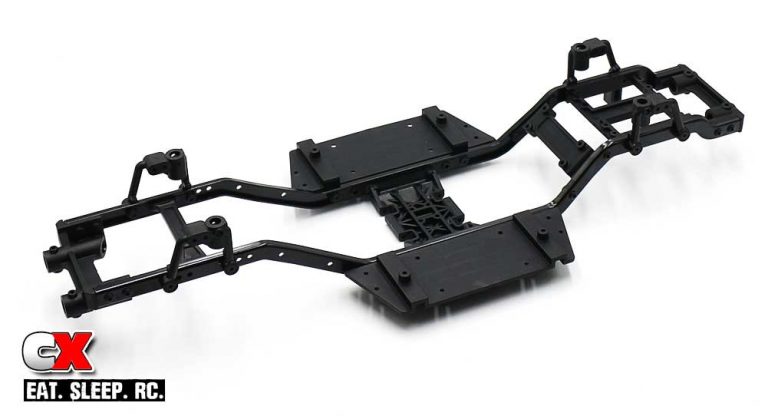
Attach the shock hoops (with the 3x12mm screws) as well as the right-side floor board (using the same screw locations and lengths from Step 2).
Step 10:
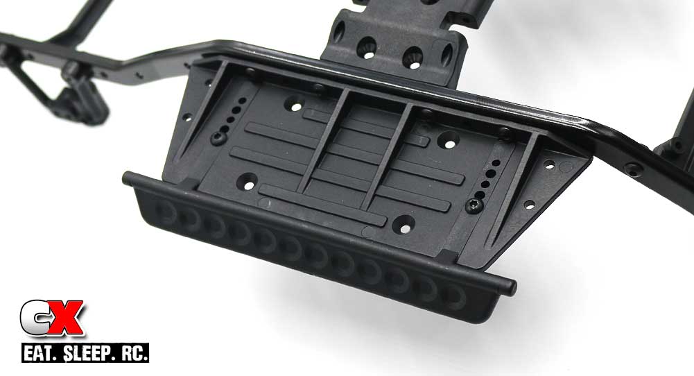
Slide the rock sliders into place and secure with the 3x12mm screws. These can be adjusted in or out depending on the body you’re using. I started mine all the way in.
Step 11:
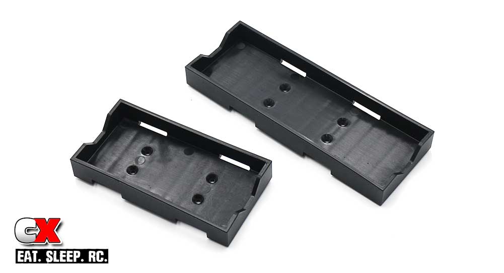
The Enduro Builder’s Kit comes with both a standard and shorty LiPo tray. The choice is yours at this point what you’d prefer to run; I’m going with the shorty setup. I have more shorty LiPos than I do standard, so it just makes more sense to go with that.
Step 12:
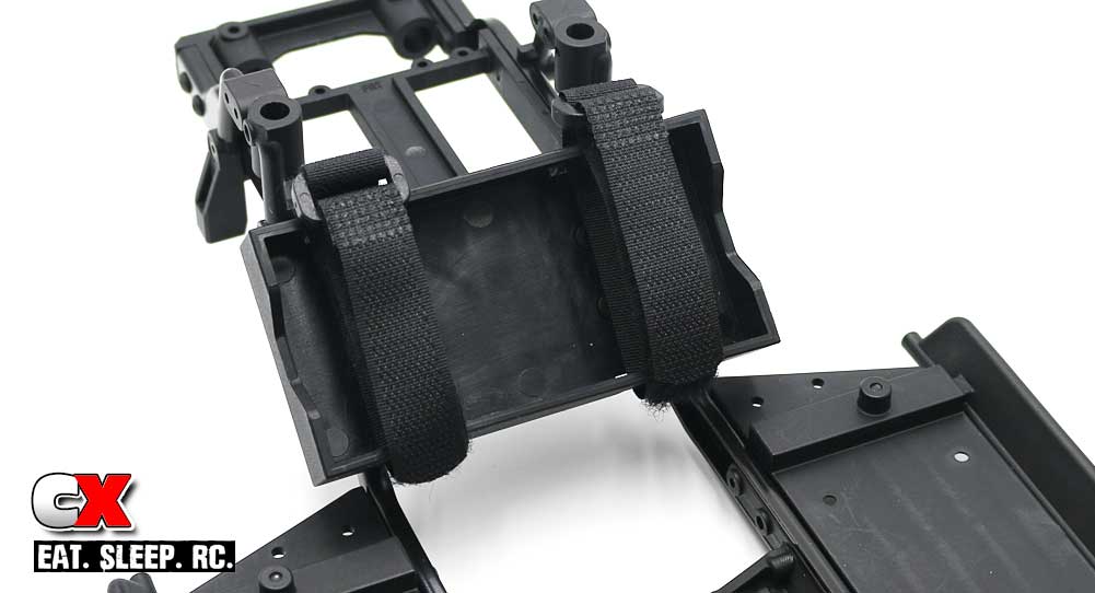
Attach whichever mount you’re going to use, then slip the Velcro battery straps into place.
Step 13:
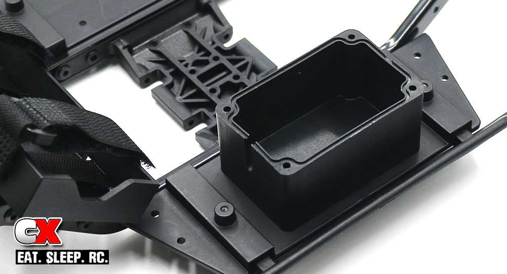
Attach the receiver box. Gotta love the size of this box – nice and roomy!
Step 14:
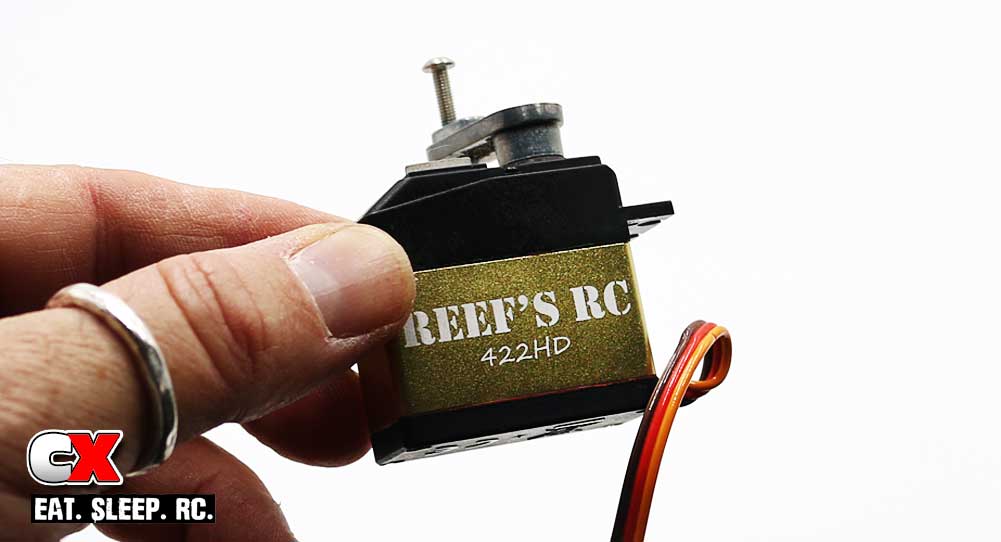
I mentioned going with the Reef’s RC 422HD servo. It’s quite the beast and will be a perfect fit in the Enduro. I also attached a metal servo horn, replacing the stock plastic one. Modification #1 of this build.
Step 15:
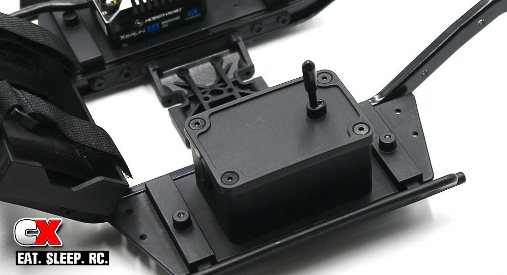
Once you get your receiver installed in the box, close it up with the silicone inserts (for waterproofing) and attach the lid.
Step 16:
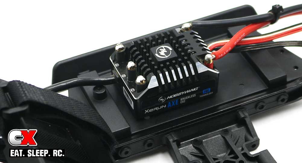
I’m also going with the Hobbywing Crawler ESC and brushless motor. Thanksfully there’s PLENTY of room on the floor boards for something of this size.
So, that’s about it for the chassis install. I’ll be working on the wiring of all the electronics at a later time; just want to make sure I get it all routed and tidy.
Element Enduro Sendero Online Build – Part 3
The transmission on the Enduro is actually quite unique. Dubbed the Stealth X, this transmission offers a couple different build options (specifically direction and Overdrive) depending on how you want the truck to perform.
Build Notes:
• If you want to build the truck as it is out of the box, the build should be easy. If you choose to alter the Overdrive, you’ll need to pay close attention to how it all works. It’s not that difficult, but you do need to swap out two gears and mount them accordingly. Use page 24 of the manual to see the different transmission mounting and gear ratio options.
I’ll be building the truck with the motor mount facing the rear, Overdrive at 12%.
• Blue threadlocker is highly suggested during these steps as well. You don’t want screws coming loose in the transmission when you’re out deep in the trails.
Step 1:
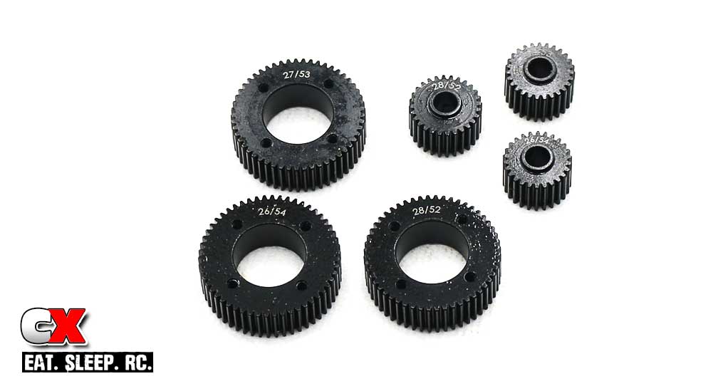
A quick look at the gears used inside the Stealth X transmission. As you can see, they’re all metal – even the gear combo is printed on all the them! Details I tell ya!
Step 2:
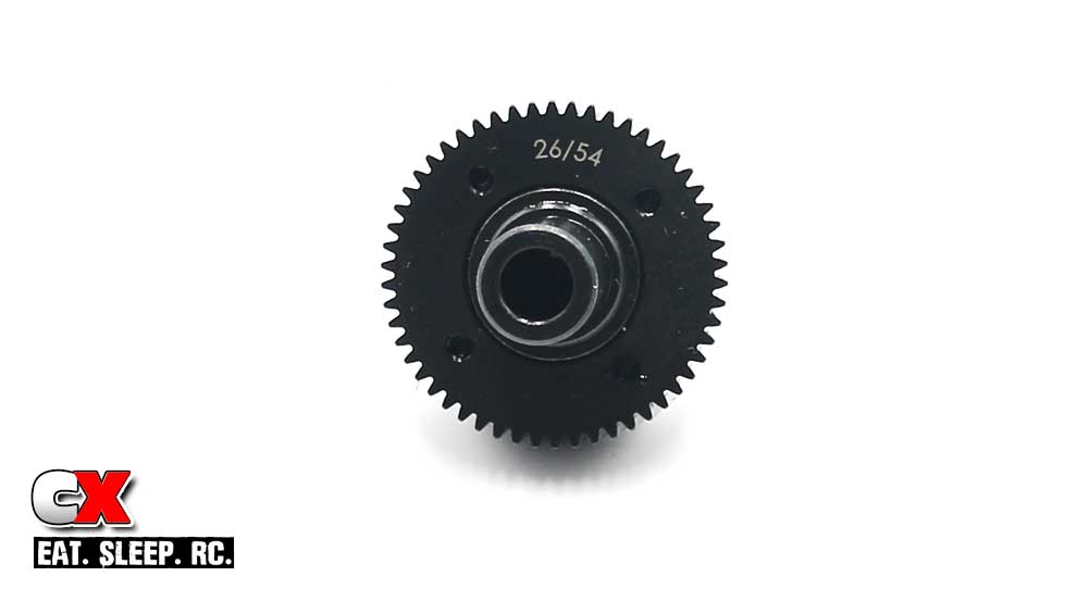
Assemble the rear output gear section – 26/54. Use a little bit of blue threadlocker on the screws to help keep them in place.
Step 3:
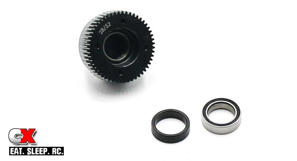
Assemble the front output gear section – 28/52 gear. You may need to firmly press the first 10×15 bearing into the gear recess. Follow that with the gear shim and second 10×15 bearing.
Step 4:
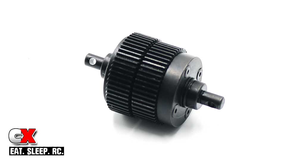
Mate the two gear assemblies together. Note the gap between the gears; if it appears a bit wide, you can tap the completed assembly on a table to help fully seat the first 10×15 bearing. I had to do this on mine to help close the gap up some.
Step 5:
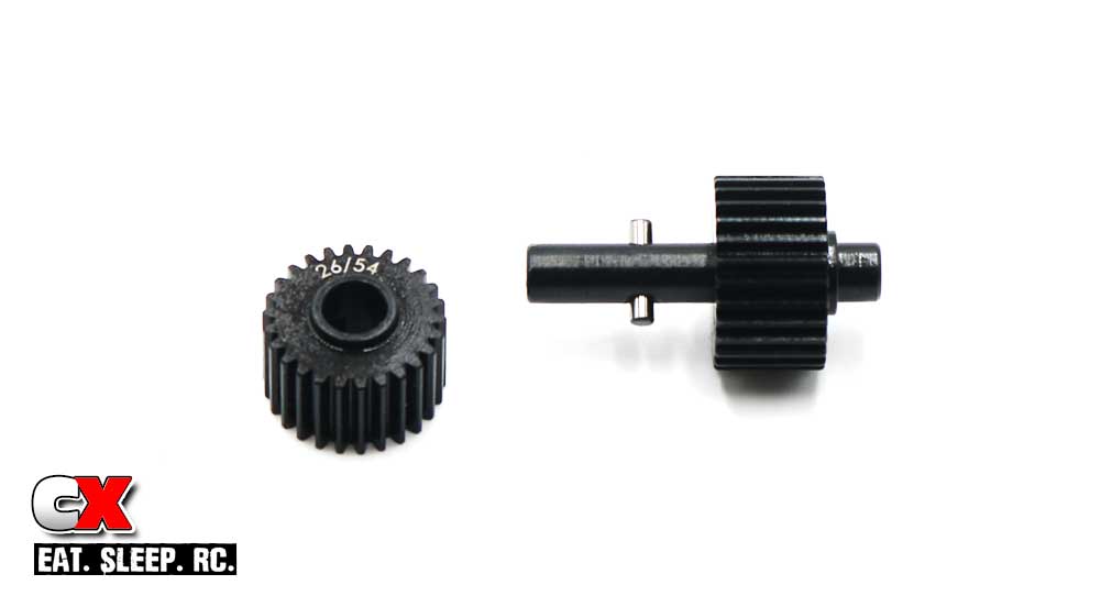
Assemble the idler shaft, making sure to match the correct gears with the ones used in Steps 2 and 3.
Step 6:
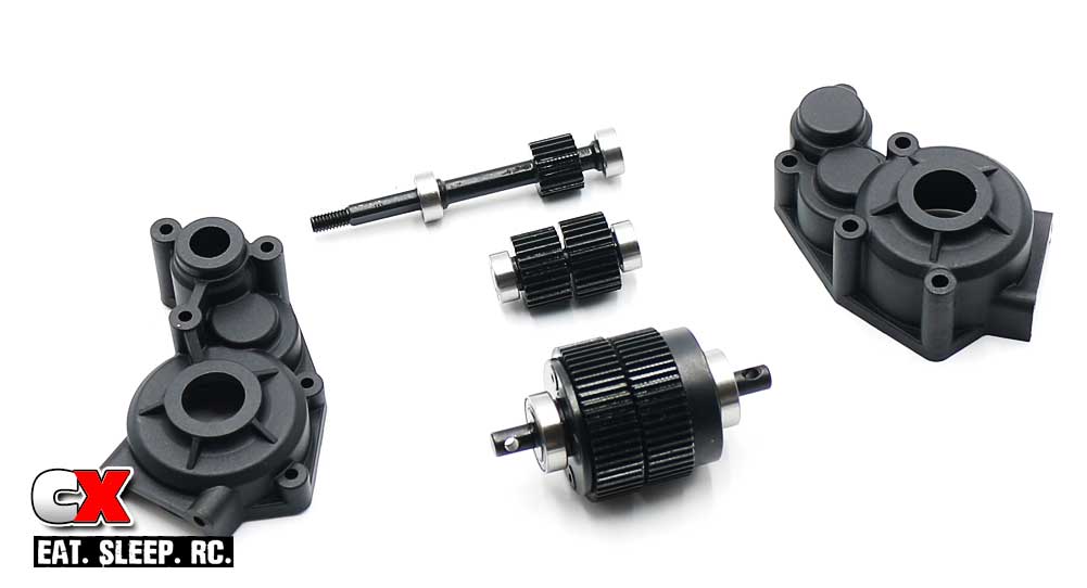
Slide the 5×10 bearings onto the top shaft and idler shaft; slide 10×15 bearings on the lower gear set.
Step 7:
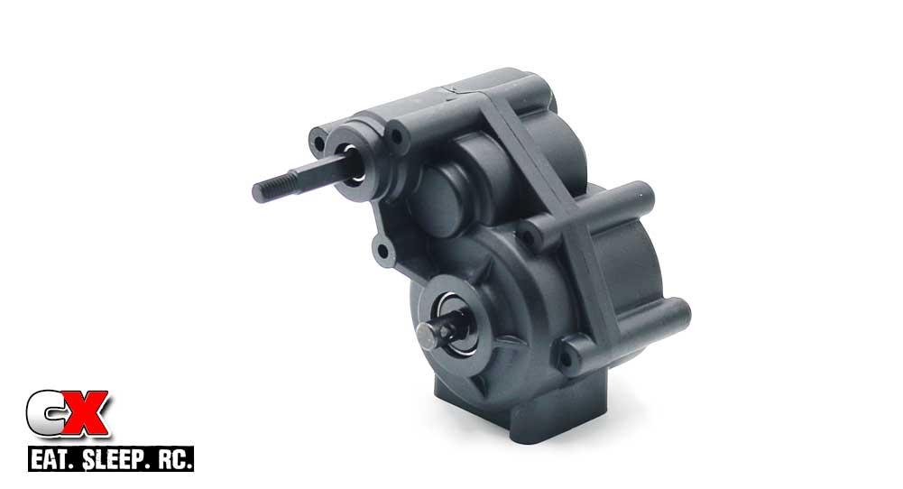
Assemble everything into the Stealth X transmission case, adding a little black grease to all the gears. If the case doesn’t slide together easily, you either need to tap on the lower gear set more to close the spacing (see Step 4) or your gear sets are not matched correctly.
If all goes together smoothly, you can secure the case with the 5 3x26mm screws.
Step 8:
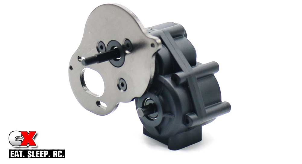
Attach the motor plate.
Step 9:
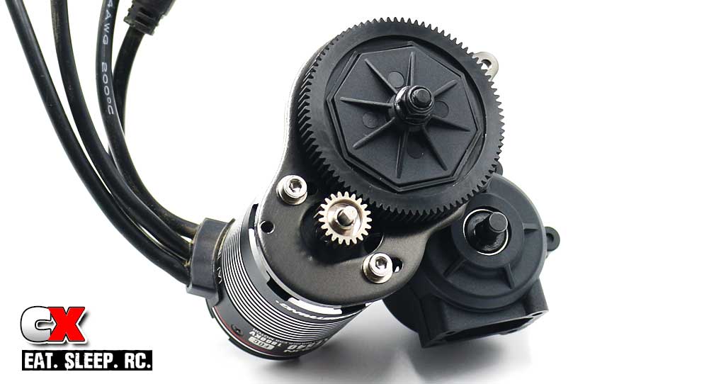
Assemble the spur gear and hubs onto the top shaft and secure with the M4 locknut. Mount your motor to the motor plate and attach your desired pinion.
I opted to swap out the supplied 3x8mm buttonhead screws for a larger caphead screw – I feel I can get more torque when tightening these down (to hold the motor in place). Modification #2.
Step 10:
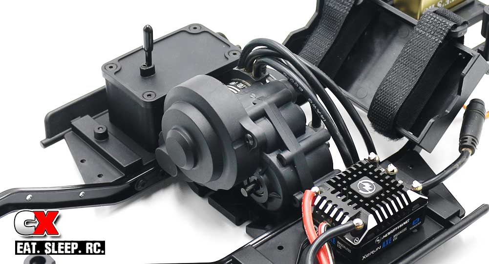
Attach the gear cover to the transmission, then the entire assembly to the chassis.
I’m happy that the transmission goes together easily as I may have to try the reverse-mount setup as well as all of the Overdrive options! That being said, we’re done with the Stealth X transmission – let’s move on to Part 4 – the Axles.
Element Enduro Sendero Online Build – Part 4
The Enduro uses a nicely molded pair of front and rear axles. Both incorporate steel lockers and oddly small input pinions, both having some major helical cuts to them. You’ll also get a taste of BTA steering, or Behind The Axle. This drastically increases the approach angle of the rig!
Build Notes:
• Early on in the build, you’ll encounter two instances of 2.5mm screws, both 14mm and 16mm lengths. Make sure you pay attention to where these go – they look very similar.
Step 1:
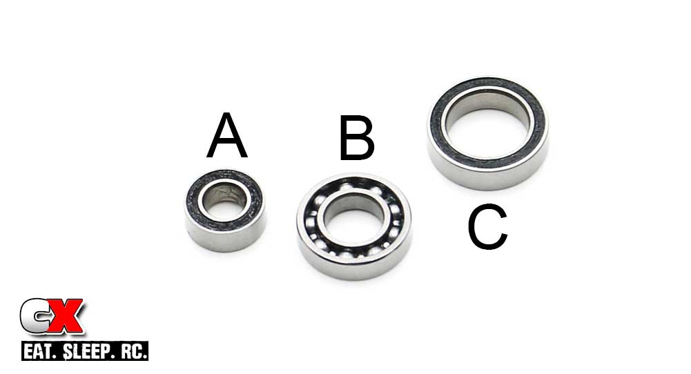
Before we build, I wanted to show you the three different bearings involved in this Step. A is a 5x10mm, uses for the input pinions. B are 7x14mm and come without any dirt shields; used on each side of the lockers. C is a 10×15 and are used in the steering blocks. Just an FYI.
Step 2:
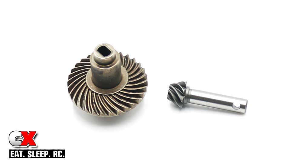
A look at the helical cut locker and pinion. One of the smalled pinions I’ve seen used in a trail rig, but the heavy helical cut should provide a ton of strength.
Step 3:
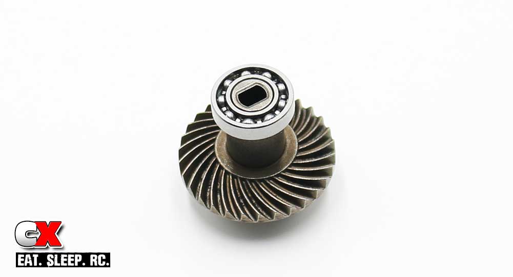
Ok, on to it. Press a 7×14 bearing on to each side of the locker unit.
Step 4:
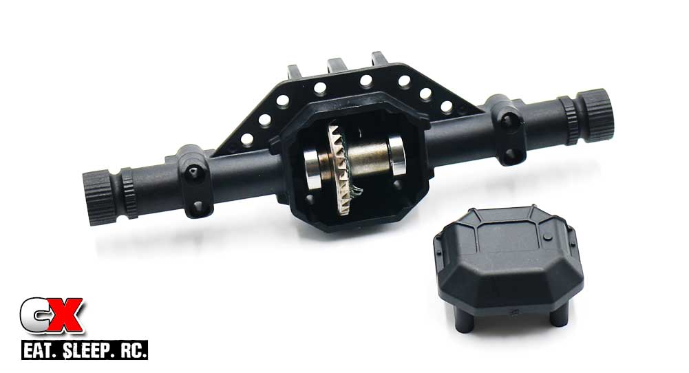
Slide a 5x10mm bearing on the pinion output shaft and press it into the axle case. Set the locker assembly into the axle case. Spread a liberal bead of black grease onto the gears, then press the axle housing cover into place, securing with the 4 2.5x16mm screws. Note the direction of the axle housing cover (see picture).
Step 5:
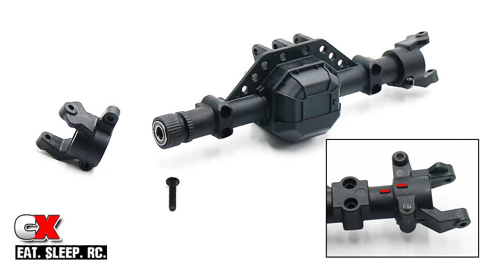
Press a 5x10mm bearing into the end of the axle, then slide the caster blocks onto the axle and secure with the 3x14mm screw. Note the inset; the caster blocks key to the axle (see red marks). This is a good starting caster setting. You can rotate the block to experiment with more or less caster.
Step 6:
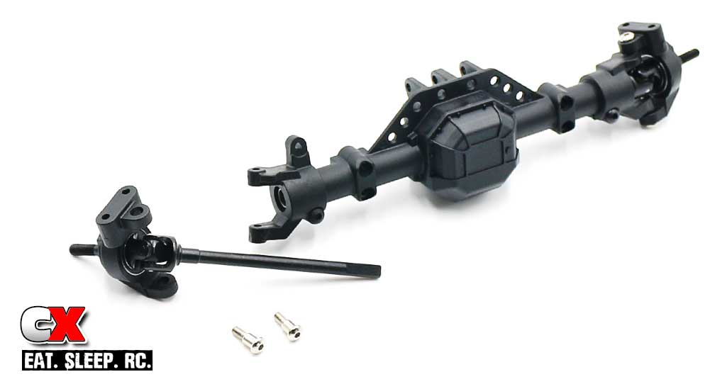
Press a 10x15mm bearing into the backside of the steering block, then slide a front universal assembly into place. Slip the universal into the axle, making sure to key the flat spots with the opening in the locker. Once fully inserted, use the 3x4mm shoulder screws to secure everything in place. Do not overtighten – just snug them down.
Step 7:
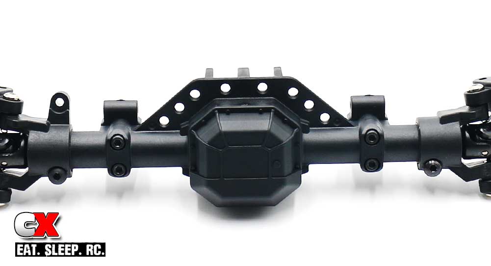
Attach the lower 4-link mounts with the 2.5x14mm screws.
Step 8:
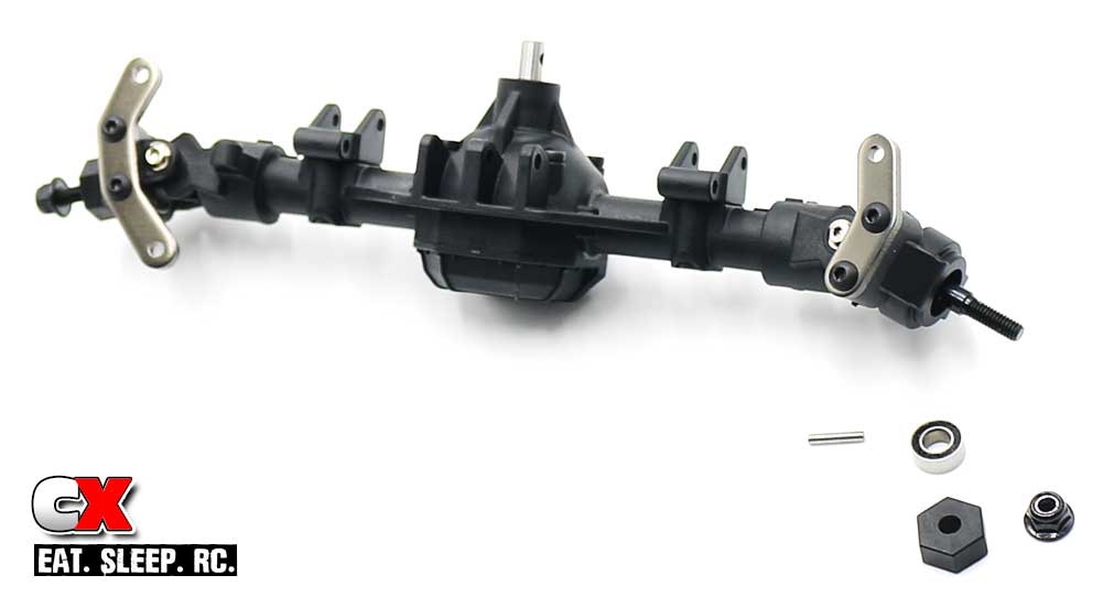
Mount the left and right steering plates as shown.
Install a 5x10mm bearing into the end of the axle housing followed by a wheel pin, wheel hex and wheel nut. Set this assembly aside.
Step 9:
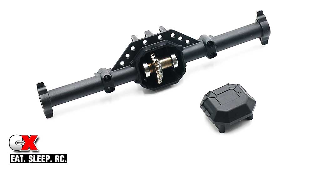
The rear axle is assembled like the front; bearing on the pinion (pressed into the axle), 7x14mm bearings onto the locker, pressed in place, add a little black grease and cap it all off with the axle housing cover. Secure with the 2.5x16mm screws.
Step 10:
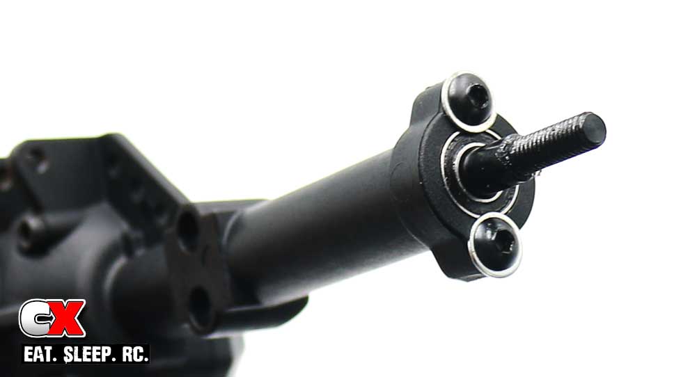
Slide the rear axle into place, keying the flat spots on the end to the slots in the locker. Press a 5×10 bearing into place and secure with the 3x6mm buttonhead screw.
Modification #3 – I wasn’t sold on the itty bitty, teeny tiny amount of screw head keeping the bearings in place, so I added a thin shim behind the screw. I feel better now.
Step 11:
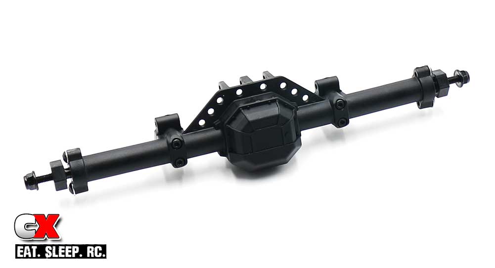
Attach the lower 4-link mounts with the 2.5x14mm screws. Add the wheel pin, wheel hex and wheel nut and your rear axle is complete!
There you have it – a pair of purpose-built axles ready to be mounted under our rig. So, let’s get to that – Part 5 – Links!
Element Enduro Sendero Online Build – Part 5
The Enduro comes with some pretty serious, chrome-plated steel links under it. Element RC also includes different lengths for you to adjust the wheelbase; simply build using the correct lengths for 11.8″, 12.0″ or 12.3″ options.
Build Notes:
• Due to the tolerances in the plastic, building the links can be a bit tedious. The manual suggests black grease on the threads to make assembly easier, but I often use Chapstick for this procedure. Everyone has Chapstick.
• The links are not marked in any way, so it’s best to have a pair of calipers handy to measure them. There is a visual notation in Step 1 below that denotes the lengths; you can use this as a form of measurement if you don’t have calipers handy.
• The plastic pivot balls that are popped into the rod ends are directional. Pay close attention to the orientation of the flange; in most cases, you’ll want the flange to be against the surface the link is being attached to.
• As a note, you’ll be building all of the links using the curved plastic rod ends.
Step 1:
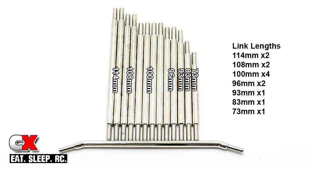
Before you build, lay out the links to get acquainted with what is available. You won’t be using all of them in the build; some are optional rear links to adjust the wheelbase to your desired build length.
The kit comes with the following links:
• 114mm x2 Rear Lower Links
• 108mm x2 12.3 Rear Upper Links
• 100mm x4 12.0 Front Lower Links, Rear Upper Links
• 96mm x2 11.8 Rear Upper Links
• 93mm x1 Front Axle Link
• 83mm x1 Panhard Link
• 73mm x1 Steering Link
• Curved Steering Link x1
We’ll specify which ones go where during the build. You may proceed.
Step 2:
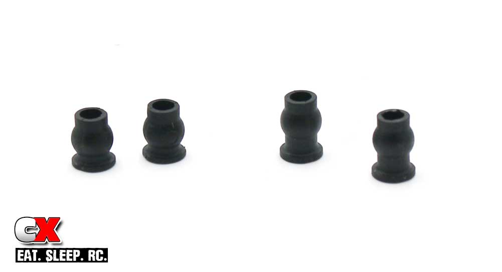
Something to also note are the different length pivot balls that come on the plastic tree. There are short ones and long ones; we’ll be using ONLY the short ones on all the links. The long ones will be for the shocks in a later step.
Step 3:
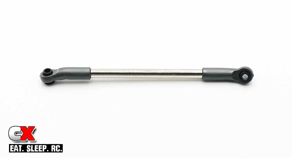
The first link we will build is the panhard rod. Grab the 83mm rod and screw on a pair of curved rod ends. Once assembled to 112.5mm, pop the pivot balls into the rod ends. Note the orientation of the pivot ball flange.
Step 4:

Attach the panhard link, connecting it from the panhard chassis mount to the axle.
Step 5:
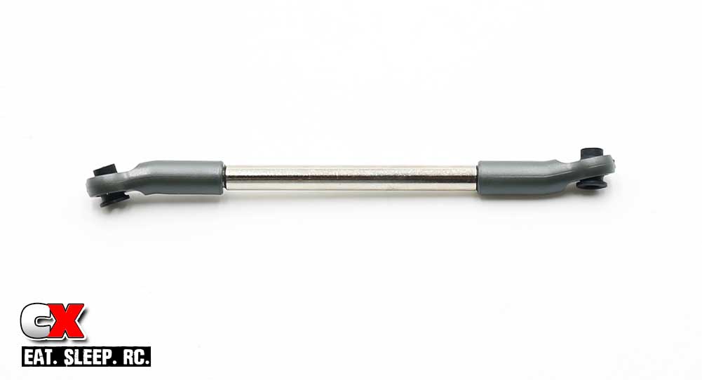
The next link we’ll build is the steering link. Grab the 73mm rod and, once built to the 102.2mm length, pop the pivot balls into the rod ends.
Step 6:
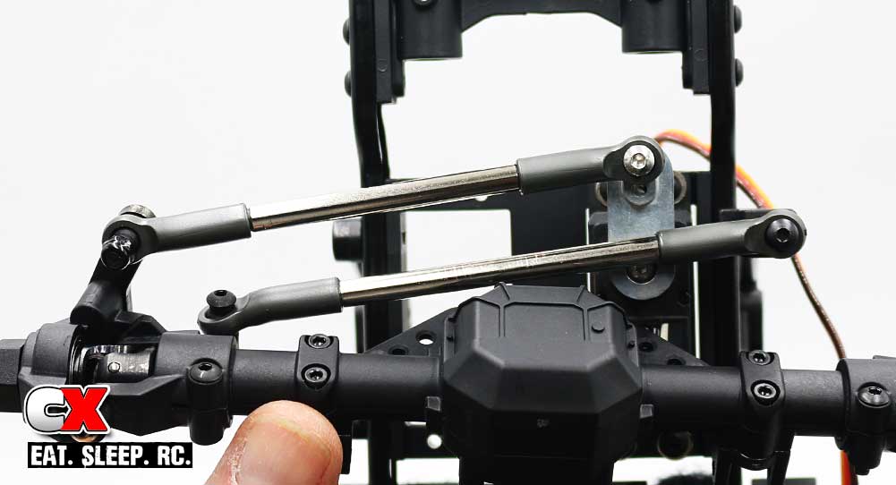
Attach the steering link from the servo to the right servo plate.
Step 7:
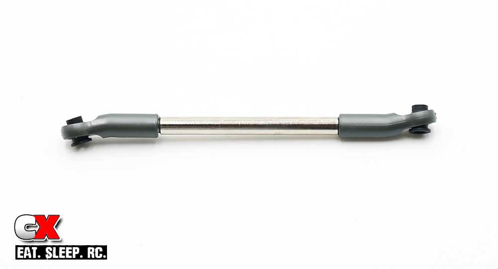
Now, grab the 93mm rod and assemble the front upper chassis link. Build to 122mm and pop the pivot balls into place.
Step 8:
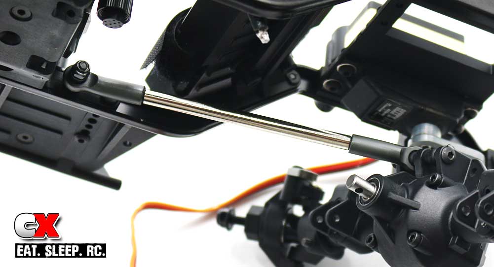
Attach the front link. Since we’re using a panhard rod, we won’t be installing a second upper link. However, to keep the 3x28mm screw from collapsing the axle mount, we need to install a stand-alone short pivot ball. Don’t forget this step!
Step 9:
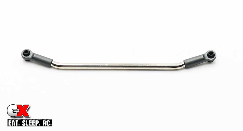
Grab your curved steering rod and add the two STRAIGHT rod ends to a length of 154.5mm. Pop a pair of pivot balls into place.
Step 10:
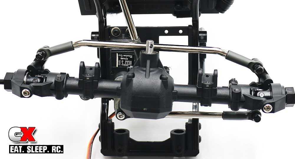
Attach the steering rod to the steering plates BEHIND the axle. Yes, well done with this BTA option!
Step 11:
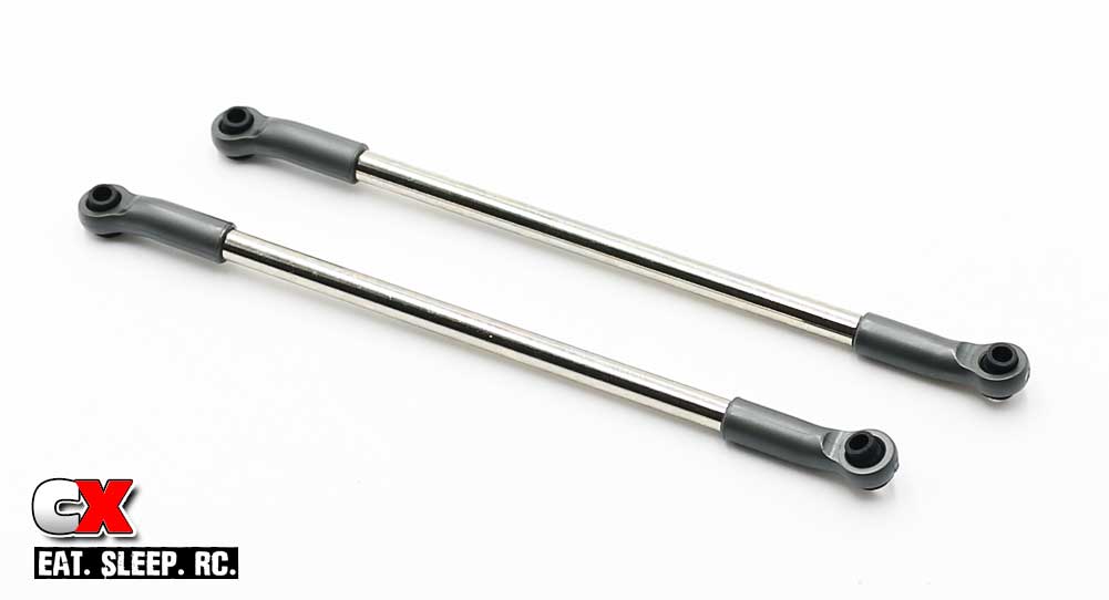
Here’s where you’ll need to decide on what wheelbase you want to build to. Your options are:
• 11.8″ (299.7mm) – use the 96mm rods
• 12.0″ (304.8mm) – use the 100mm rods
• 12.3″ (312.4mm) – use the 108mm rods
Once you’ve decided on your length, build you links with the curved rod ends and pop the pivot balls into place.
Step 12:

Once built, attach the rear upper links in the same fashion as you did the front upper link.
Step 13:
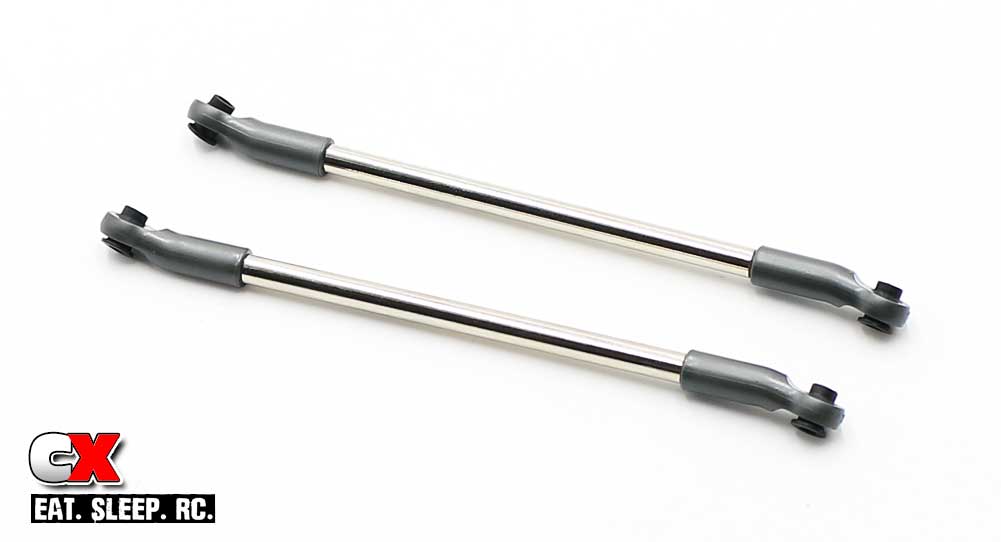
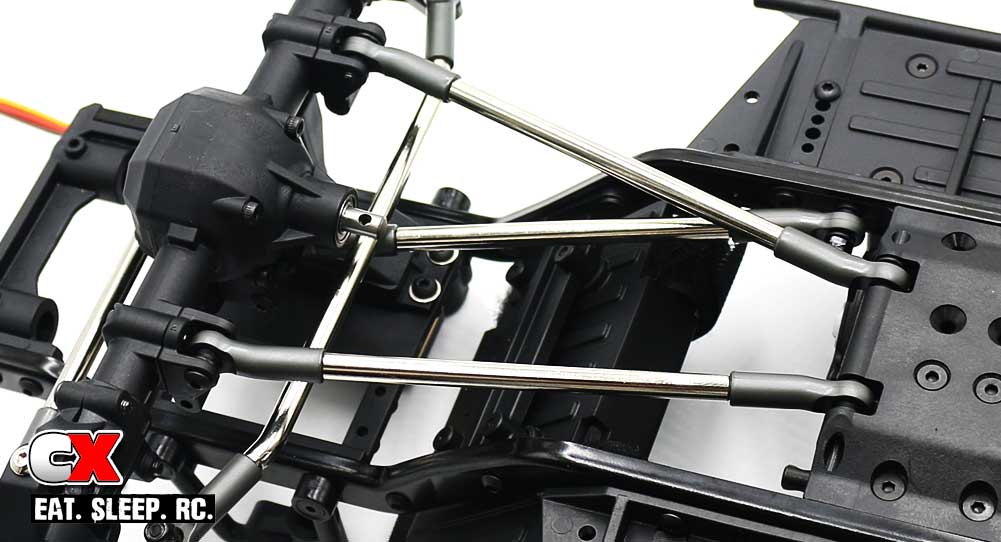
Grab a pair of the 100mm rods and build your front lower links. Complete length should be 129.5mm. Pop the pivot ball ends into place.
Step 14:
Attach the front lower links. I would suggest only screwing the 3x16mm set screw in until it’s flush with the hole.
Step 15:
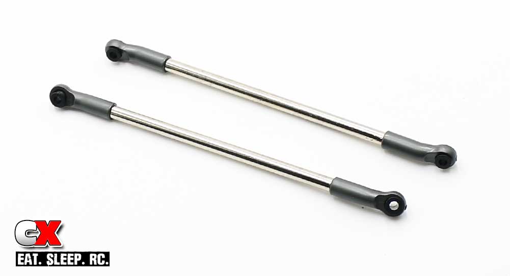
Finally, take the 114mm rods and build a pair of rear lower links. Build to 143mm, then pop the pivot ball ends into place.
Step 16:
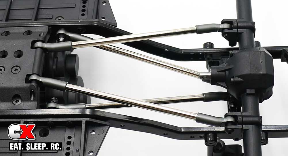
Attach your assembled rear lower links. Again, I would suggest only screwing the 3x16mm set screw in until it’s flush with the hole.
Wah-lah! Give the truck a little twist to make sure everything flexes smoothly. If there’s any notchy feeling, you may have built something incorrectly. Otherwise, you’re good to go! Let’s get to Part 6 – the Drive Shafts!
Element Enduro Sendero Online Build – Part 6
The drive shafts included with the Enduro Builder’s Kit use a combination of plastic females and an aluminum insert. The splines are large, making for a very stout driveline. The aluminum insert virtually eliminates ‘flex crush’; when a typical plastic hollow insert starts to twist under load and then collapses. No worries of that happening here.
Build Notes:
• You’ll want some blue threadlocker handy early on for the screws going into the male CVA parts.
• You’ll also want to pay close attention to the lengths of the parts; 3 of the plastic shafts are 33mm, 1 is 42mm. The aluminum insert are also different lengths; the front one is 48mm, the rear is 60mm.
• There is also something called drive shaft phasing; basically the way the drive shafts spin in relation to their connection points. The manual has a diagram at the bottom; just make sure you adhere to the mounting instructions and you’ll be good to go.
Step 1:
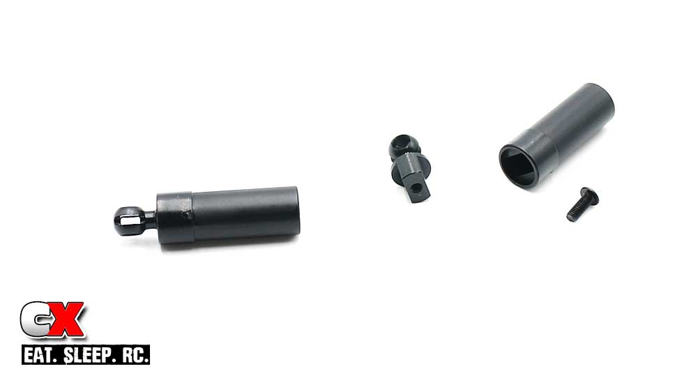
Step 1 is to build all 4 of the female drive shaft parts. Blue threadlocker is highly suggested here. It doesn’t really matter how you build them; we’ll separate and assemble correctly in later steps.
Step 2:
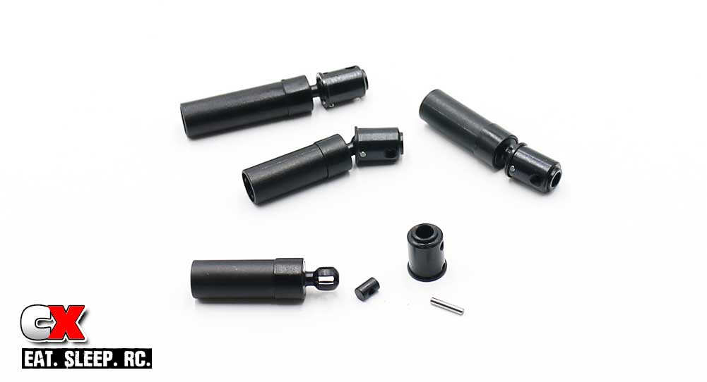
Assemble the metal barrel, pin and CVA ends. If the pins keep falling out, you can apply a light dab of black grease to keep things in place.
Step 3:
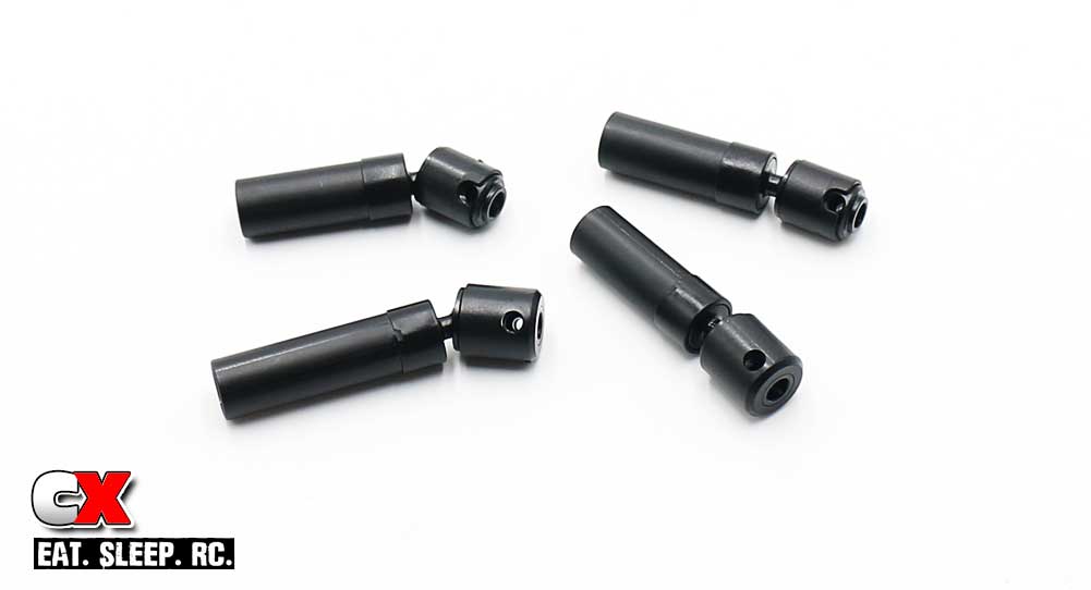
Slip the pin retainers onto each CVA. Pay attention to the holes in the retainers; one side is larger than the other and should be aligned to the threaded hole in the CVA end.
Step 4:
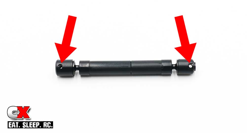
Slide the plastic halves over the aluminum insert; shown is the final drive shaft assembly with the correct ‘phasing’. Red arrows denote the mounting points.
Step 5:
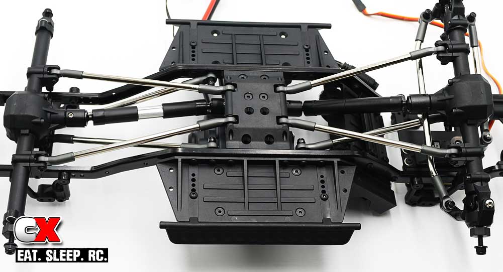
I would love to tell you that this final step went off without a hitch, however I’d be lying. While trying to install, the pin retainers don’t stay in place and the opposite side I was installing would continually slide off, causing the pin to drop out and my drive shaft to fall apart. This happened about 4 times before I needed a new install technique. I removed the drive shafts from the aluminum insert and installed the gearbox side first. I then slipped the aluminum insert into place, reconnected the 2nd drive shaft half and connected that to the axle. This made the install WAY easier as I only had to deal with 1/2 of the drive shaft at a time.
Oh ya, make sure to add some blue threadlocker to the screw pins prior to installation.
Drive shafts done! Time to assemble some shocks – Part 7!
Element Enduro Sendero Online Build – Part 7
Element RC has included a stellar set of aluminum shocks with the Enduro Builder’s Kit. Seems like a very Factory Team option; aluminum bodies with blue aluminum caps, collars, bottom caps and spring retainers. Silky smooth goodness.
Build Notes:
• Seeing the amount of work the Element RC team put into this truck, I’m going to start with the kit supplied 30wt oil. Probably good for most situations.
• You’ll want to have some sort of shock stand and paper towels handy. Shock oils can get messy so make sure your work surface is also covered.
Step 1:
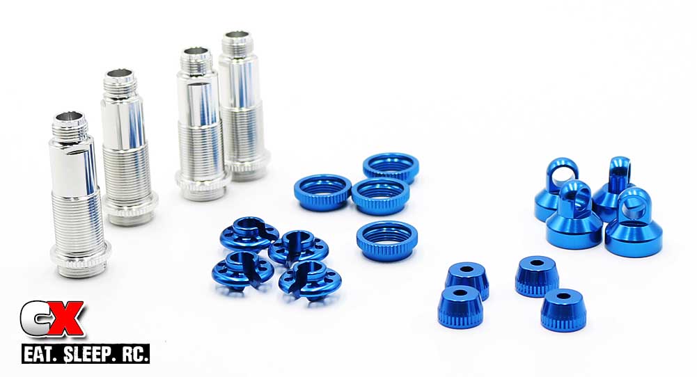
Before we assemble, I just want to give a shout out to all the aluminum included in the Enduro Builder’s Kit. I know some high-end race kits that don’t include shocks this pretty.
Step 2:
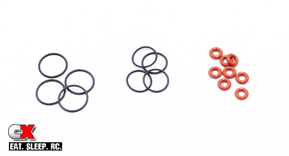
I also like to separate the o-rings prior to building as well. The larger, black o-rings are for the shock collars, the smaller, black ones for the upper shock body and the right ones (red ones) surround the shock shaft.
Step 3:
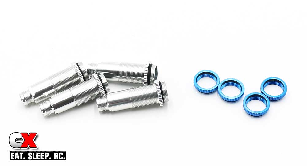
As with all my builds, I like to install the shock and collar o-rings up front. Trying to do this with any shock fluids on your hands can result in a large amount of 4-letter works exiting your mouth.
Step 4:
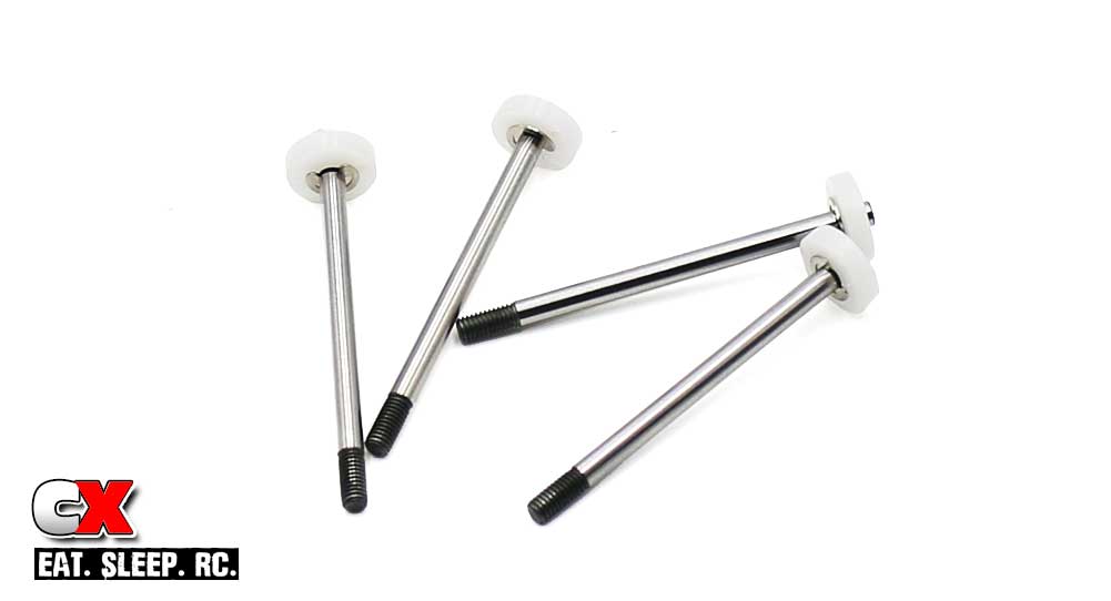
Ok, on to the build. Install a piston onto each shock shaft. All the pistons and shafts are the same – just build.
Step 5:
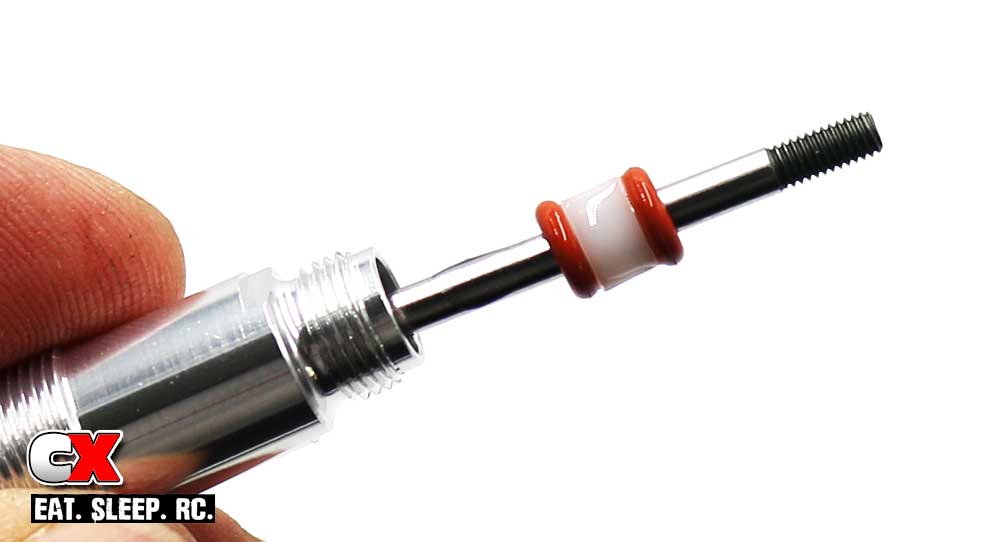
I like to build the lower shock cartridge area a little different than most. Slide the shaft into the shock body, then slip on the lower parts (o-ring, spacer, o-ring). Add a light dab of oil to the o-rings and shaft and slide these parts up into the lower shock area.
Building the shocks this way helps prevent the threads on the shaft from potentially tearing the o-rings during installation.
Step 6:
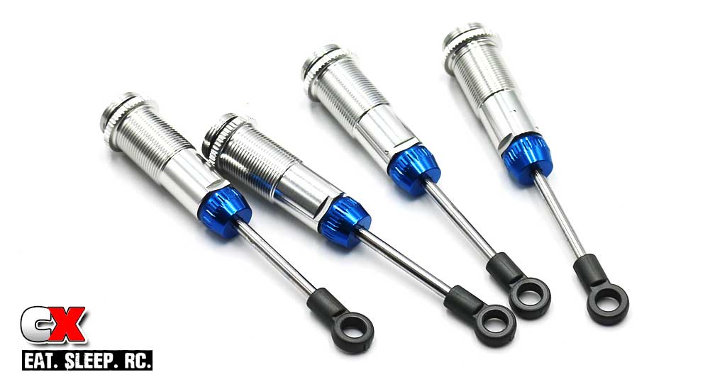
Screw on the lower shock cap, then install the short straight rod ends to each shock shaft.
Step 7:
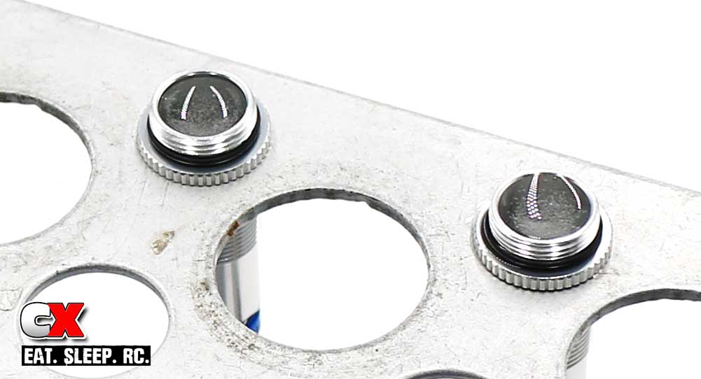
Fill the shocks with oil. Plunge the shaft up and down a few times (slowly) to release any air bubbles from under the piston. Set aside in your shock stand until the bubbles have disappeared.
Step 8:
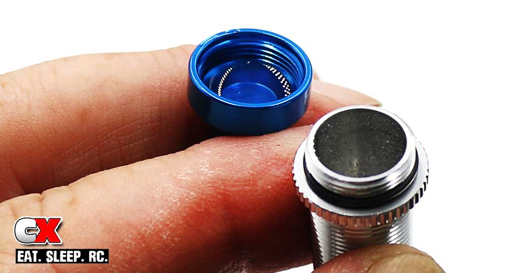
I like to add a little more oil to the shock – just enough until the oil is flat across the top. Add 2 drops inside the cap, flip the cap over and screw onto the top of the shock. I only screw it on about 4 turns.
Set the shock down on a piece of paper towel and slowly compress; once the shock is fully compressed, screw the cap all the way on. You may see a little bit of oil release as you’re doing so. This is fine. Just make sure you follow the exact process for the other three shocks.
Step 9:
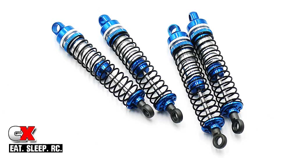
Once bled, install the shock collar, spring and retainer. Boom – shocks done! Beauties, right?
Step 10:
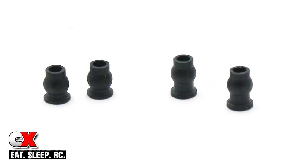
Here we are again, back at the short and tall pivot balls. For the next steps, we’ll be using the tall pivot balls on the upper shock mounts, the short pivot balls on the lower.
Step 11:
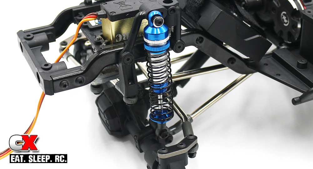
Attach the front shocks. Do not overtighten.
Step 12:
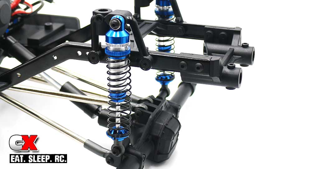
Attach the rear shocks. Do not overtighten.
You can adjust ride height by moving the shock collars up or down. There are also multiple holes in the upper mounts for adjusting shock ‘tension’.
Good job – clean up any mess you might have and let’s get to the final step – Part 8 – Body Mounts.
Element Enduro Sendero Online Build – Part 8
The final step in the Element RC Enduro Builder’s Kit are the body mounts. Element RC supplies a single (short) body post solution up front, however two options for the rear. You can use a similar single body post (like the front) or a taller, cross-braced dual post (for taller bodies).
Build Notes:
• Replacing the body posts is a quick, 15-second process. If you’re not sure on your body selection just yet, do what I did and just install the shorties for now.
Step 1:
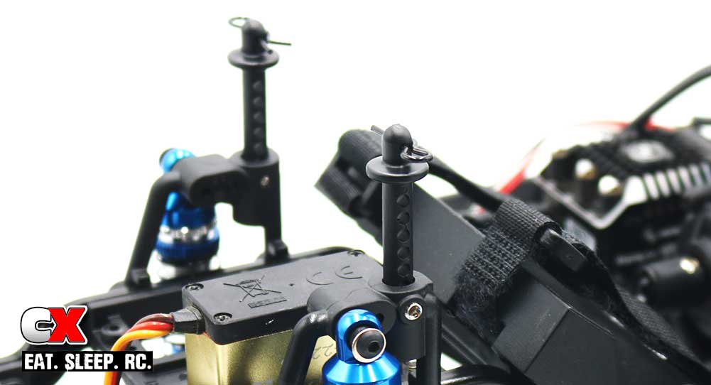
Install the front body posts.
Step 2:
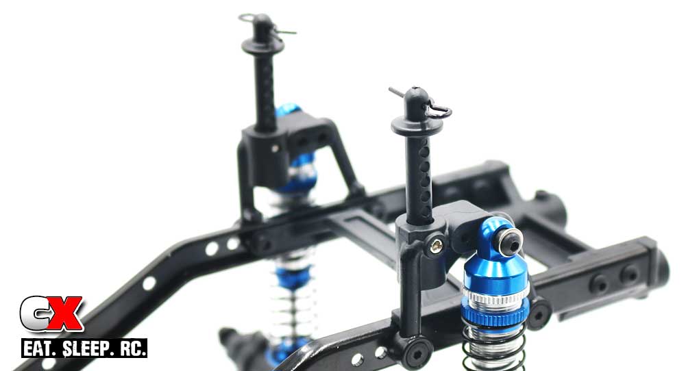
Install the rear body posts. Done. LOL
And there you have it. Two SUPER easy install steps to finish off your Enduro Builder’s Kit.
The only thing you have left to do is decide on a body, wheels and tires (maybe electronics if you didn’t install them earlier). Get those installed and get your awesome ride outside! I can’t wait to do that with mine!
Thanks for following along with the Element RC Enduro Builder’s Kit. If you have any questions, please don’t hesitate to ask!

