
Tamiya TRF419XR Touring Car Online Build
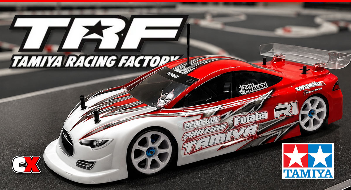
Tamiya touring cars are a very rare site – maybe it’s the price – it’s a pretty huge chunk of money for a product when there are other options available for less. That, however, sometimes doesn’t matter if the car is worth it.
Working at Tamiya now, I thought it was probably time to pick one of these unicorns up and give it a go. The current TC is the TRF419XR, a carbon-equipped, blue-aluminum shod high-end road rocket that is of top-notch quality and design. It comes with Tamiya’s stellar TRF shocks, double cardan universal shafts, front spool, all kinds of aluminum bits and 2.25mm lower/2mm upper carbon decks. It even has a cool little aluminum fan mount!
I’m excited to get this car outside and see if it’s as good as the price says it is. But first, we need to get it built.
Tamiya TRF419XR Online Build – Part 1
The Tamiya TRF419XR comes with a 2.25mm lower and 2mm upper deck as standard equipment. Both are machined from high-quality carbon fiber with blue-anodized aluminum parts bolted to it.
In this step, we’re going to be attaching the bulkheads, inner front/rear arm mounts and steering posts.
Build Notes:
• In the past, we’ve sanded and sealed the edges of our carbon parts before assembly. This, however, has led to some mixed feeling about the way the sealed edges prevent the chassis from flexing like it should. So, for the TRF419XR, we are not going to seal anything.
• Most of the screws feed into aluminum parts; again, we would normally use blue threadlocker to help keep the screws in place. This too seems to be a product of discussion regarding possible flex issues. While I would suggest blue threadlocker on any screw going into aluminum, I chose to only use it in certain areas. Those will be called out.
Step 1:
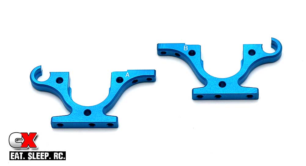
The front and rear bulkheads are directional, designated by the A and B printed on them. Another way to check left and right is the ‘lip’ on the U-part of the bulkhead; that lip should be to the outside of the car.
Step 2:
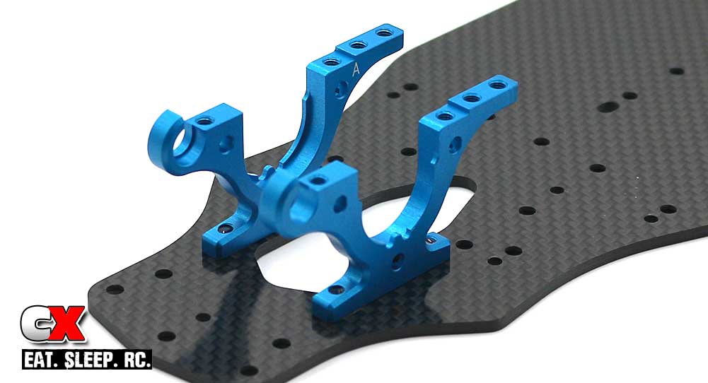
Attach the left and right bulkheads to the front of the carbon chassis. Note orientation.
Step 3:
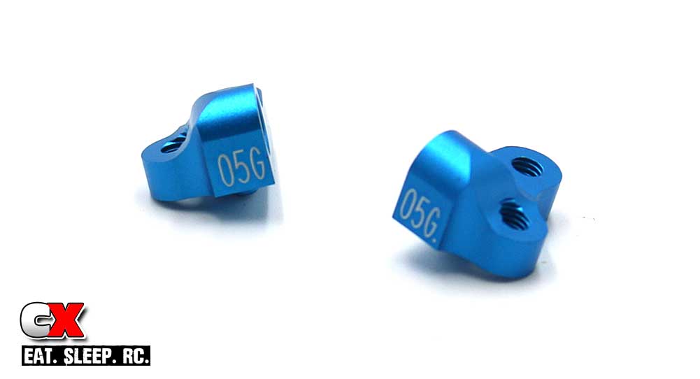
The TRF419XR uses 05G front inner arm mounts.
Step 4:
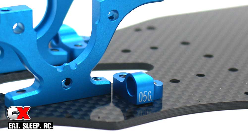
Attach those to the chassis as shown. Blue threadlocker is OK to use here.
Step 5:
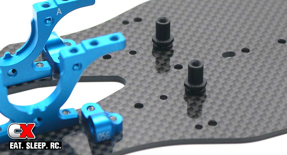
Attach the steering posts. Blue threadlocker is OK to use here as well.
Step 6:
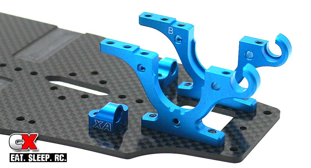
Moving to the rear, attach the left and right bulkheads and the XA rear inner arm mounts. Blue threadlocker on the XA mounts is suggested.
Step 7:
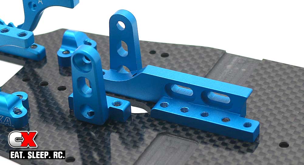
Attach the two motor mount halves to the chassis. Note the holes used for attachment. You can add additional screws to change the flex characteristics.
That was a simple few steps – not difficult at all! Clear some space and let’s get to Part 2 – the rear differential!
Tamiya TRF419XR Online Build – Part 2
Like most current touring cars, the Tamiya TRF419XR comes with a front spool and rear gear differential setup. The rear is a sealed unit that accepts any diff fluids; we’ll be building ours with 3K fluid to start.
Build Notes:
• As with most differential builds, this could be a messy step if you’re not careful. A covered work area and cleanup rags are highly recommended.
Step 1:
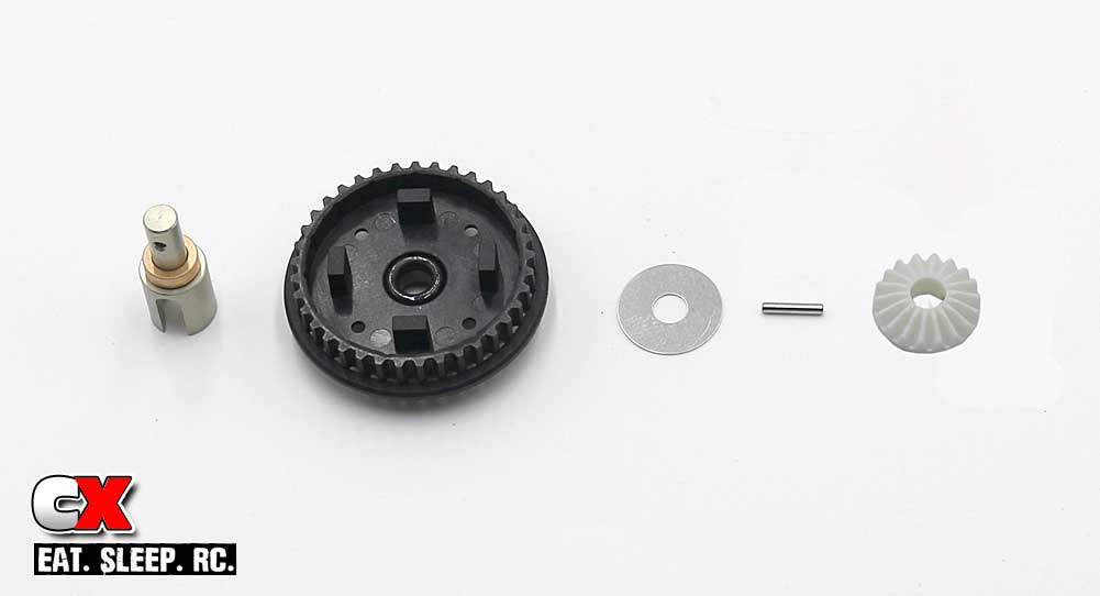
To get this step started, grab an outdrive and slide one of the metal bushings over it. Feed it through the diff pulley, then lube and slide the black o-ring over the outdrive and press it down into the pocket. Follow that with the 5×15 shim. Locate and feed the cross pin through the hole in the outdrive, then key and press the sun gear into place. The sun gear should be flush with the end of the outdrive.
Step 2:
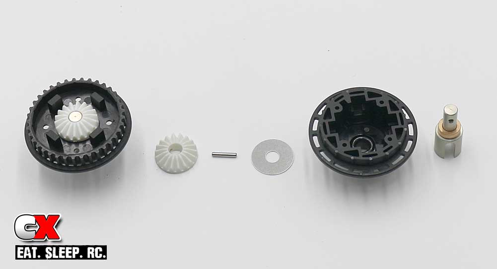
Step 2 is the same as Step 1, just the differential housing side.
Step 3:
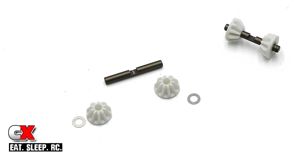
Assemble a pair of cross shafts; each should have a pair of satellite gears (facing inward) and a 3×5 shim (on the outside of the gear). Note the cut in the cross shafts.
Step 4:
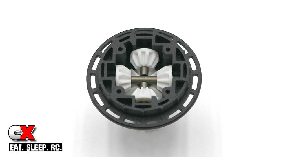
Install both satellite gear assemblies into the diff case; note how the cuts in the cross shafts key together. Rotate the outdrive a couple turns to make sure the gears seat correctly.
Step 5:
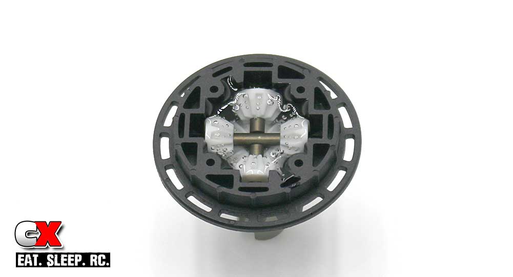
Fill with fluid. You want to put just enough to reach the top of the satellite gears. Wait a few moments for the bubbles to disappear.
Step 6:
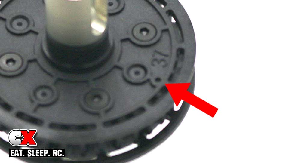
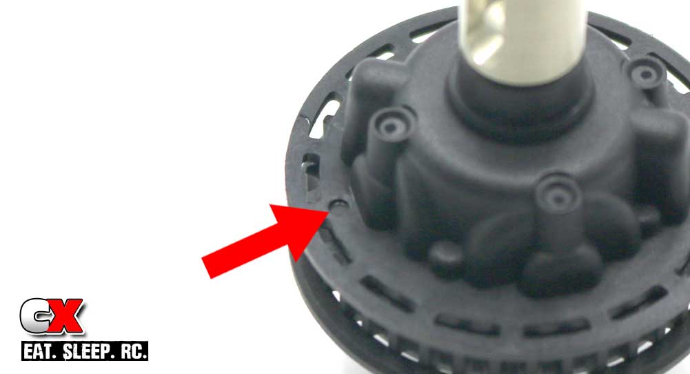
You’re going to match the two diff halves together, however you’ll need to make sure the two points shown above line up. These are the ‘key’ points to make sure diff halves mate correctly.
Step 7:
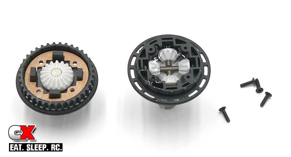
Press the gasket into the diff pulley. Mate the two halves together (see Step 6) and secure with the 4 2x8mm screws.
Step 8:
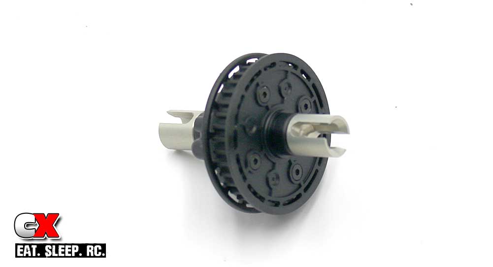
Rear differential done. You can mark the outside of the case with 3K (or whatever you used) for easy reference.
Clean up any excess fluid with a rag and some motor spray, set the diff aside and let’s move to Step 3 – the Driveline.
Tamiya TRF419XR Online Build – Part 3
Time for the driveline. The Tamiya TRF419XR is a 4WD Touring Car, using a dual-belt setup to drive all 4 wheels. The center bulkhead houses a Tamiya-pitch spur gear – that’s fine and all, however the mounting pullies utilize an odd 4-pin locator to key to the spur gear. This becomes an issue if you want to change spur gears; not all aftermarket gears have 4 holes in the locations needed for mounting.
The gears I found that work are the Panaracer-Xenon gears. They’re available in a ton of different teeth counts and have the 4 holes in the desired locations for easy mounting.
Build Notes:
• There are a few steps that require shims to tighten up tolerances. Sometimes you’ll need them, sometimes not. Pay special attention to these so you don’t have to disassemble the TRF419XR later (like I did).
• Belt tensions are critical on this car to make sure one end isn’t over-driving the other. I’ll point this out in the steps below.
Step 1:
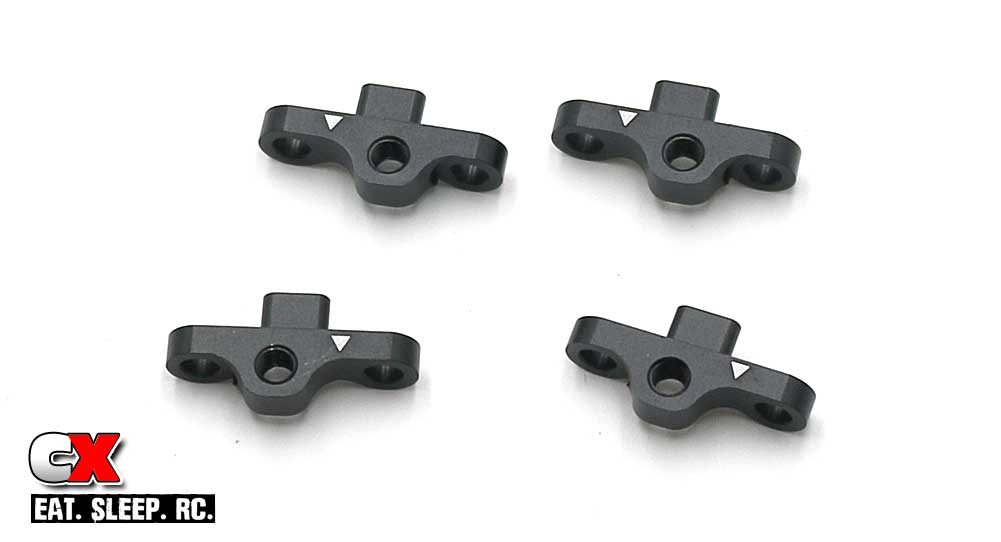
Before we start building, you’ll need to recognize the parts used. Some look similar so you want to make sure you don’t mix them up.
These are the Upper Arm Mounts. Note the differences between them; one mounts on the right, one one the left. The little white arrow will help designate which side it mounts on.
Step 2:
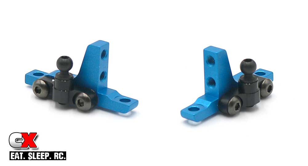
Build a left and right upper bulkhead. Note the arrows for the Upper Arm Mounts in the manual.
Step 3:
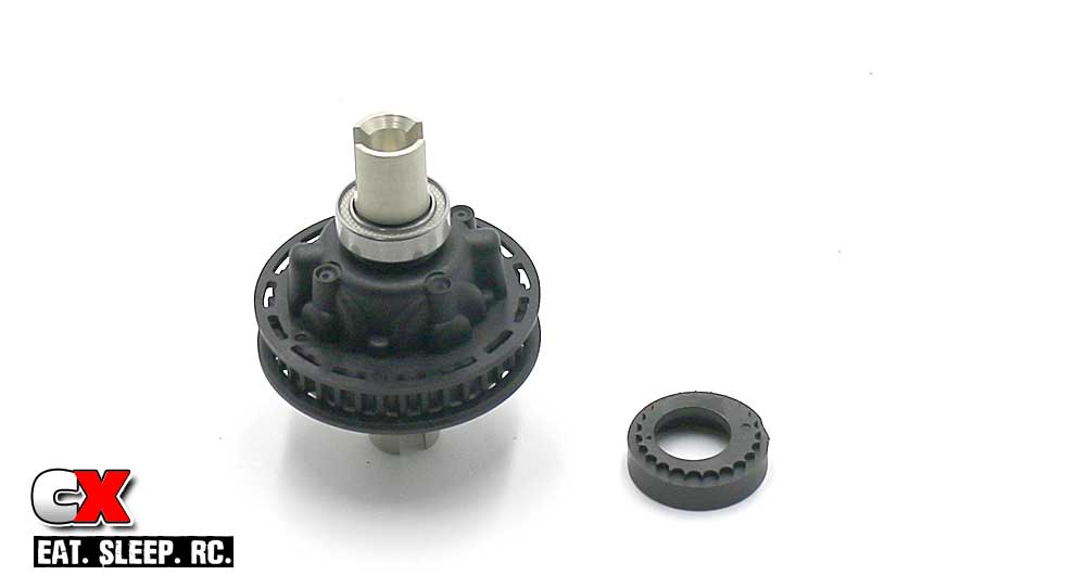
Install a bearing and cap onto both sides of the rear differential.
Step 4:
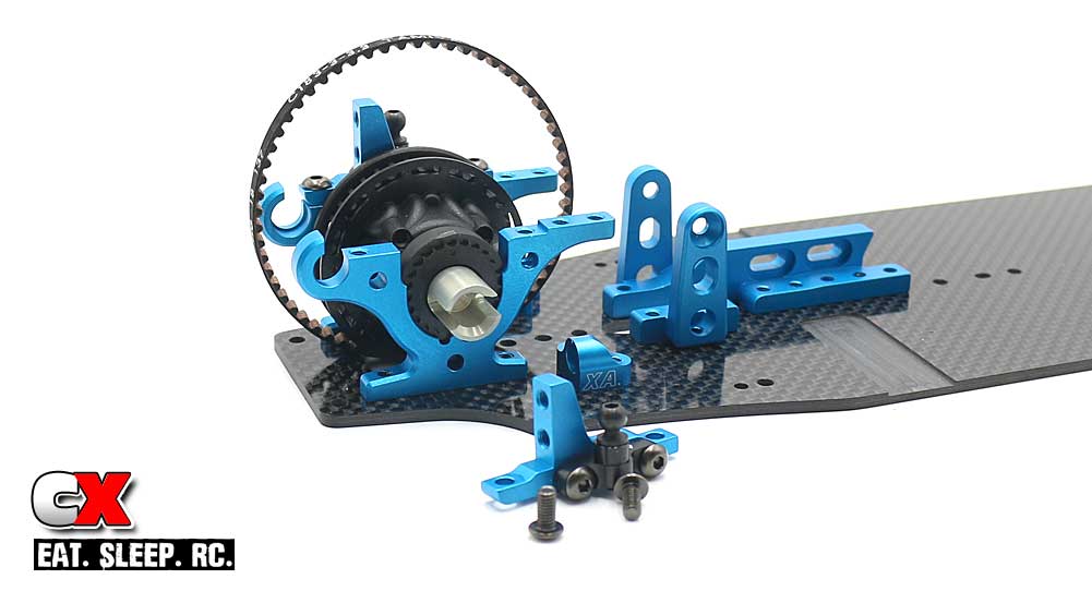
Wrap the rear belt (small one) over the diff and drop that assembly into the bulkheads. The manual shows the key point being straight up; I clocked mine forward 2 notches for a slightly looser belt. Capture the rear diff with the Upper Bulkhead assemblies from Step 2.
Step 5:
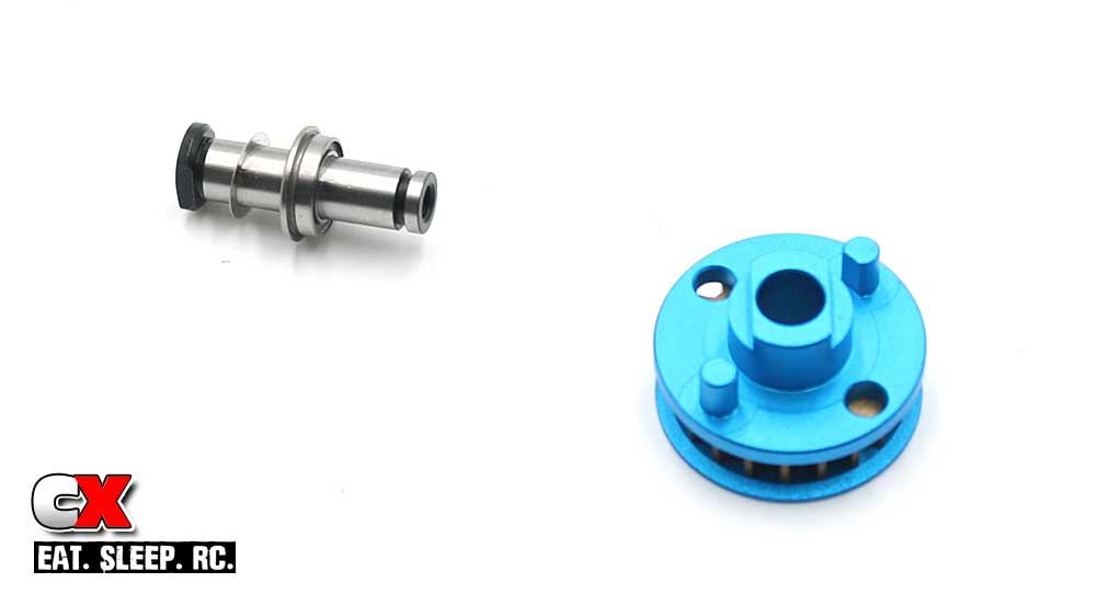
Slip a .2mm shim and flanged bearing onto the center shaft followed by the main drive pulley.
Step 6:
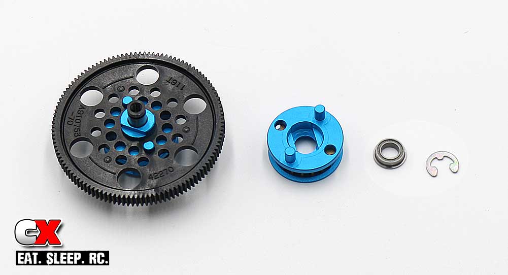
Key the assembly from Step 5 to the spur gear. Key the second drive pulley to the spur gear, then slide another flanged bearing and .1mm shim onto the center shaft and use the 4mm e-clip to capture it all.
Here is where you’ll need to experiment a little with the shimming. With this setup (on the stock gear), there was a little bit of spur gear wobble. After replacing the gear with one of the Panaracer-Xenon gears, I was able to remove the .1mm shim altogether.
Step 7:
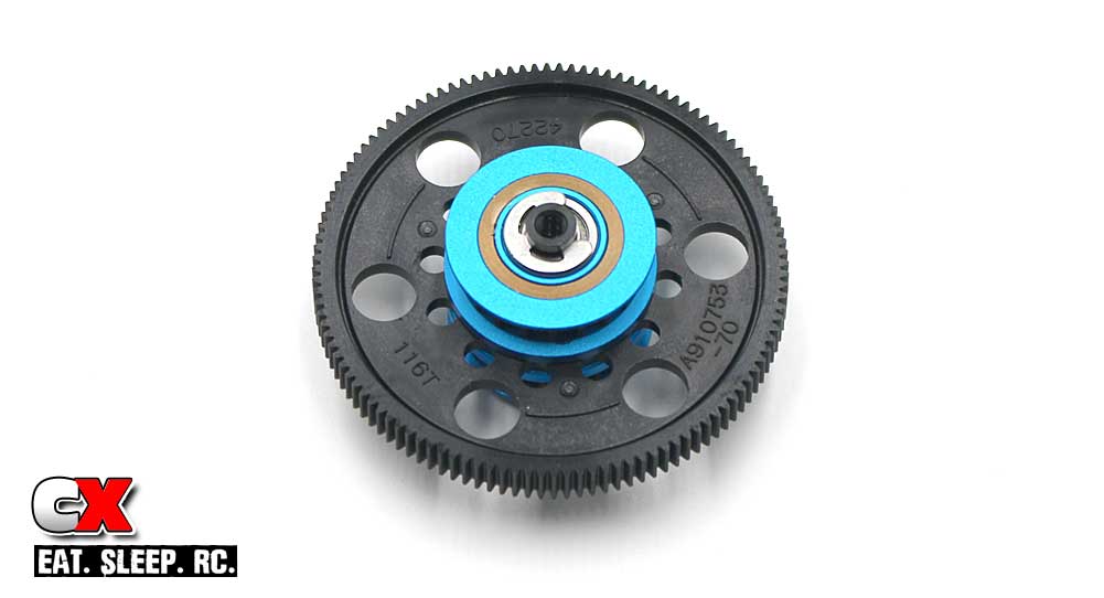
Your completed center shaft/spur gear assembly.
Step 8:
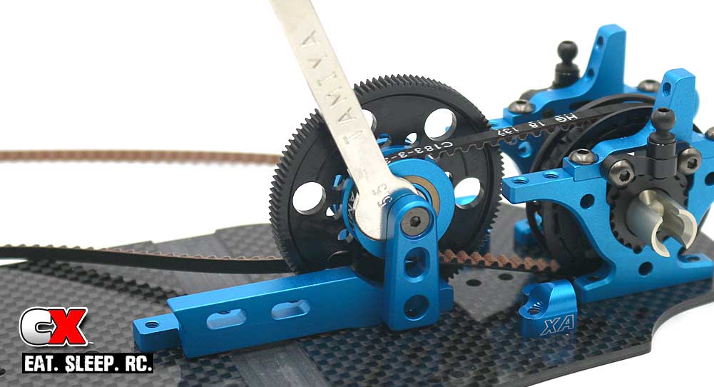
Slip the long, front belt and rear belt over the center shaft assembly and drop between the motor mount. Using the included wrench, hold the center gear assembly in place while you insert the two 3x8mm screws. A very light dab of blue threadlocker is suggested here.
Step 9:
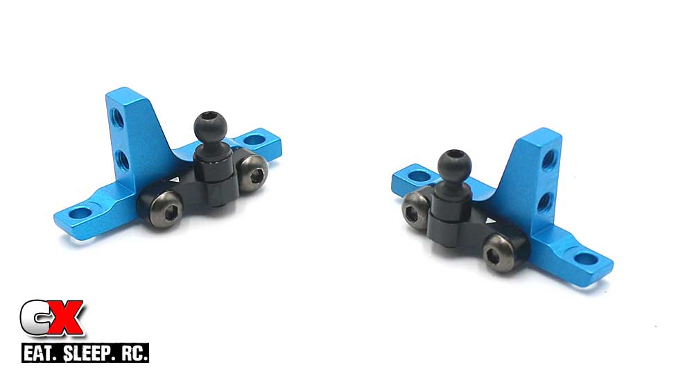
Build a pair of front Upper Bulkheads. Like the rear, pay attention to the white arrows during assembly.
Step 10:
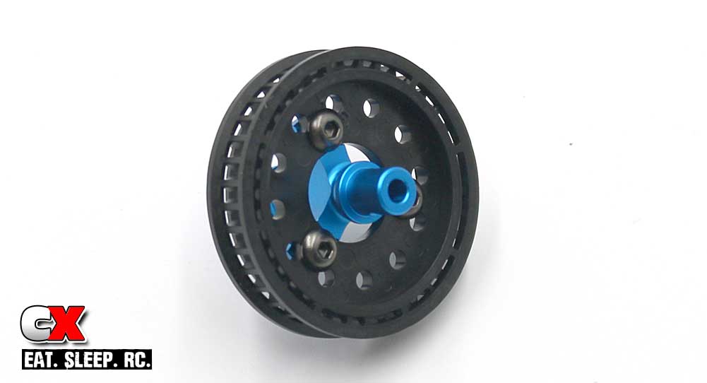
Assemble the front spool.
Step 11:
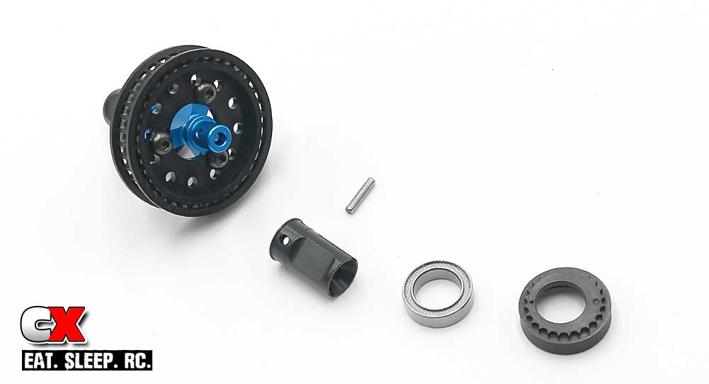
Slide the drive cups into place, secure with the drive pin and hold that in place with the large bearing. Press the cap onto the bearing.
Step 12:
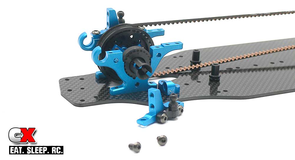
Slip the front drive belt over the spool assembly and drop into the bulkheads. Again, the manual shows it keyed straight up and down; I clocked mine back 2 notches to loosen it up slightly. Secure with the Upper Bulkhead assemblies from Step 9.
Boom – driveline done! Give the belt a little pull to make sure everything moves freely. You may need to adjust the belt tension slightly after the first couple of runs.
Let’s move on to Step 4, the Steering!
Tamiya TRF419XR Online Build – Part 4
The Tamiya TRF419XR uses a standard dual-bellcrank steering system. It is ball-raced and has aluminum turnbuckles reaching out to the wheels. Toe and Ackermann are adjustable.
Build Notes:
• Using the kit dimensions for the turnbuckle lengths seems to be a good place to start.
Step 1:
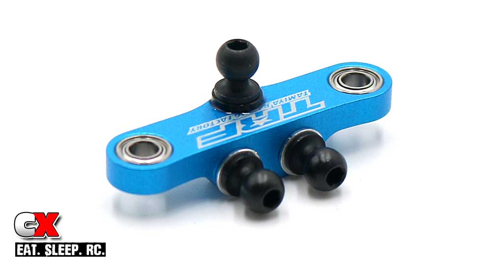
Build the steering bridge. A light dab of blue threadlocker on these ball ends is suggested.
Step 2:
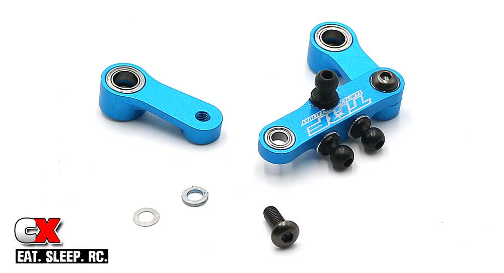
Attach to the aluminum steering arms. A very LIGHT dab of blue threadlocker is suggested; don’t get any on the shims or bearings.
Step 3:
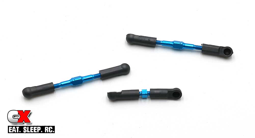
Build the 3 turnbuckles; two steering, one drag link.
Step 4:
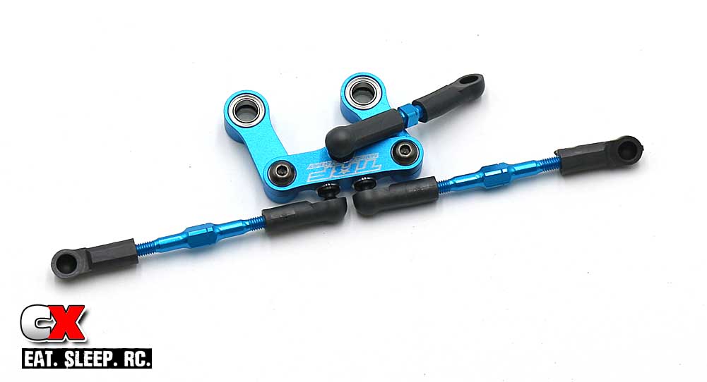
Attach the turnbuckles to the steering assembly.
Step 5:
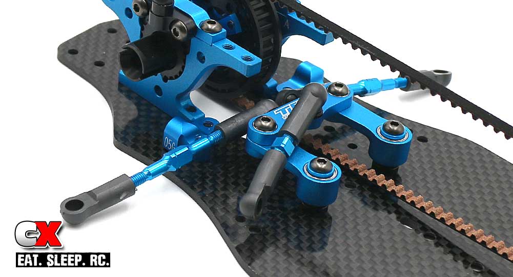
Slide the steering assembly onto the steering posts and secure with the 3x6mm screws. Blue threadlock is suggested.
That was quick and easy. Moving on to Step 5 – Suspension!
Tamiya TRF419XR Online Build – Part 5
The suspension on the Tamiya TRF419XR has always been one of the best in the industry. Precision-molded arms, aluminum arm mounts and the super-slick TRF shocks all compliment this ride’s amazing drive quality. It even comes with double cardan drive axles on the front as standard equipment.
Build Notes:
• Everything went together fine in this step, right up until Step 19. You’ll need to insert some .5mm shims that are kind of a pain. I show you, in Step 19, the way I figured it out – you may come up with a better solution.
• Tamiya includes a cap of their thick anti-wear grease. This stuff works wonders but can be a bit messy. Use with care.
Step 1:
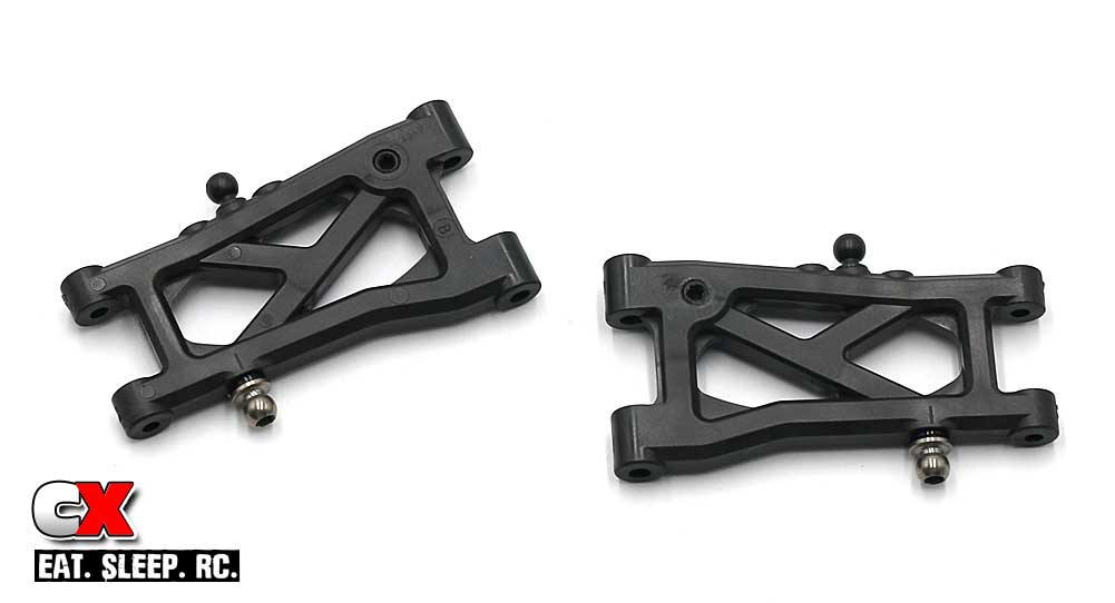
Start off this step by assembling a pair of rear arms. I sort of guesstimated the rear droop screws; I’ll give the car a full setup walkthrough prior to its first run.
Step 2:
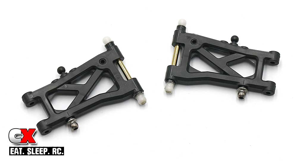
Slide the inner hinge pin through the arm and slip the 3mm, 1mm and .3mm shims into place. A light dab of Anti-Wear Grease on both ends (before slipping the 5mm suspension balls on) will help keep everything in place.
Step 3:
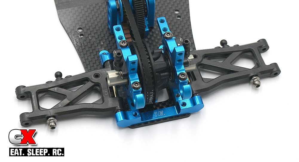
Slide the rear suspension arms into place, then capture with the 1E aluminum suspension mount. Blue threadlocker into the 1E mount is suggested.
Step 4:
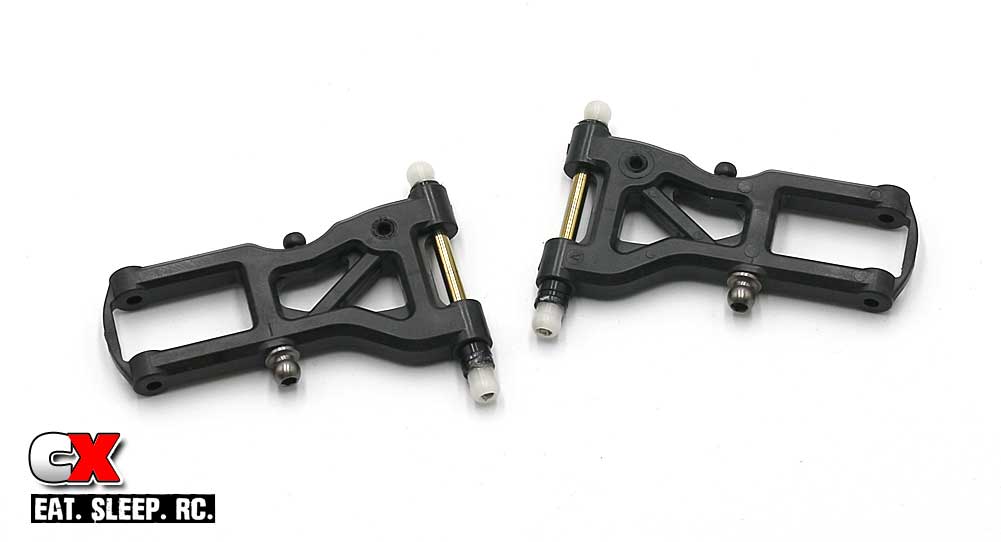
Build the front arms. Process is similar to the rear arms (Steps 1 and 2).
Step 5:
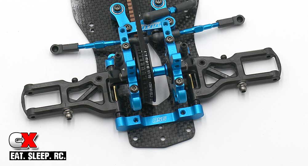
Set the front arm assemblies into place, the capture with the 05G aluminum mount. Blue threadlock is suggested into the 05G mount.
Step 6:
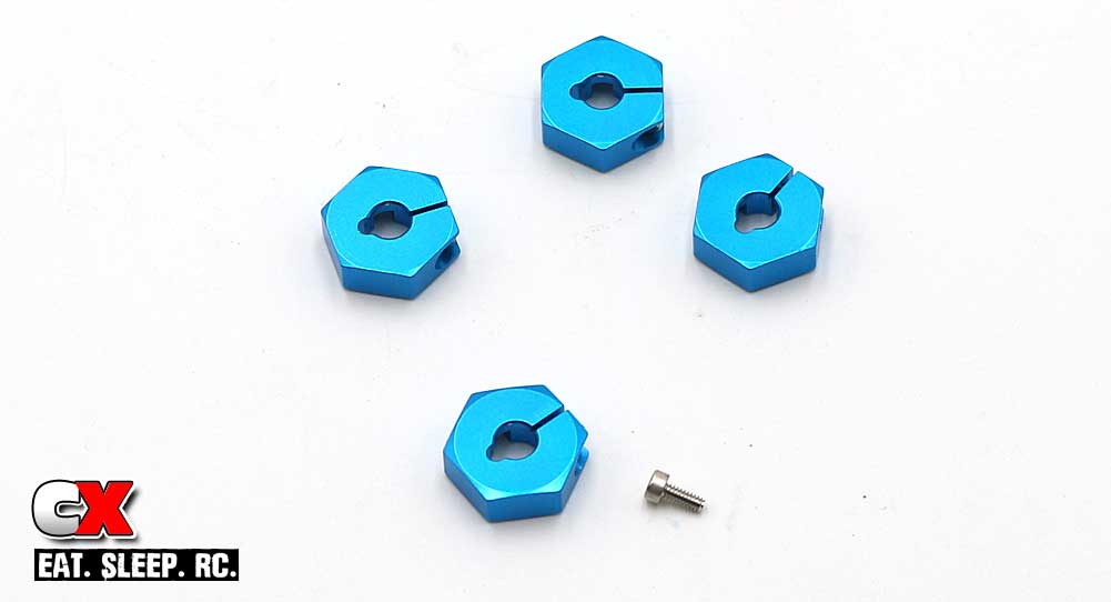
Assemble the 4 aluminum wheel hexes.
Step 7:
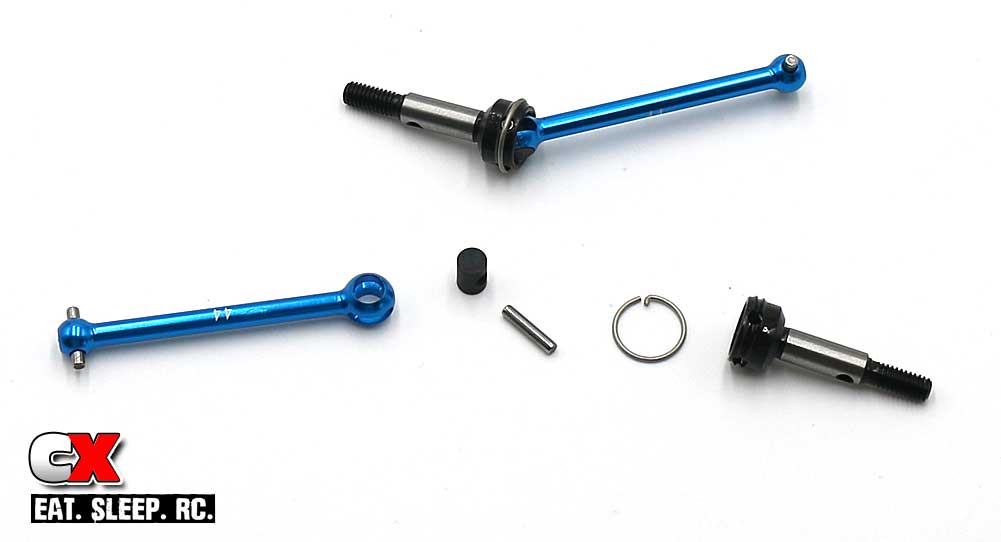
Assemble the rear universals. Anti-Wear Grease is suggested here. A little patience is also required while installing the axle ring.
Step 8:
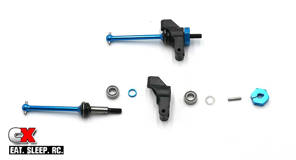
Assemble the rear uprights. Only thing to note here is the 2.5mm holes required in the uprights for the set screw. I would suggest doing this PRIOR to assembling the rest.
Step 9:
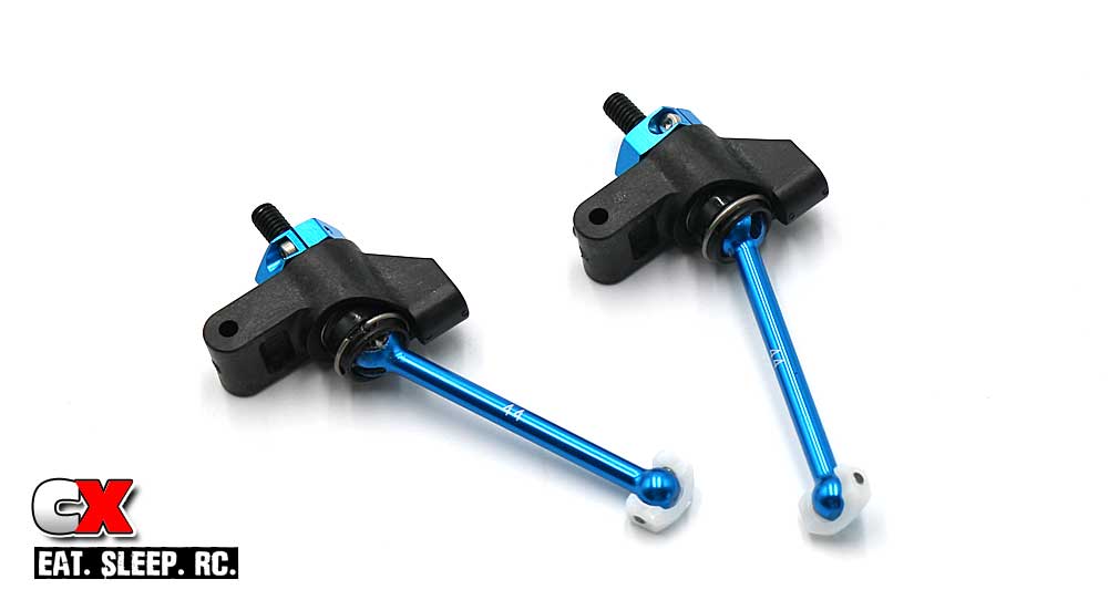
Flex and install the white axle savers.
Step 10:
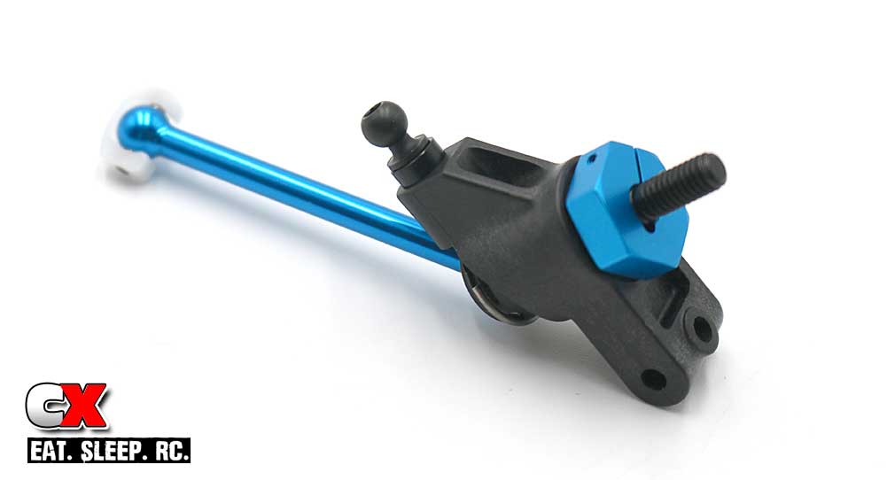
Install the 8mm ballstud and 2mm spacer on each upright. Your final assemblies should look like this.
Step 11:
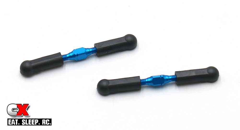
Build a pair of rear turnbuckles.
Step 12:
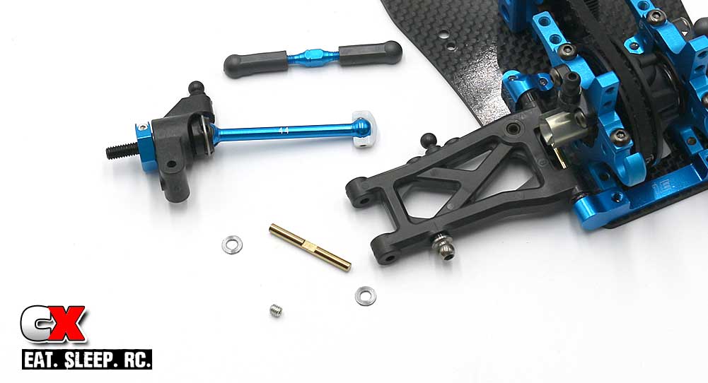
Attach the rear upright assembly to the rear arms. Make sure you get the small .5mm shims on each side of the upright assembly.
Manual shows a little bit of Anti-Wear Grease into the outdrive; I would suggest only a very little as to much could make it spray all over after the first run.
Note: the hinge pin needs to be installed with the flat spot facing out. The 3mm setscrew needs to come in contact with the flat spot to secure the hinge pin.
Step 13:
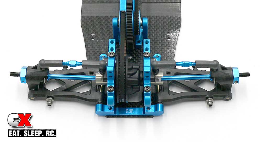
Here’s a look at the final rear assembly.
Step 14:
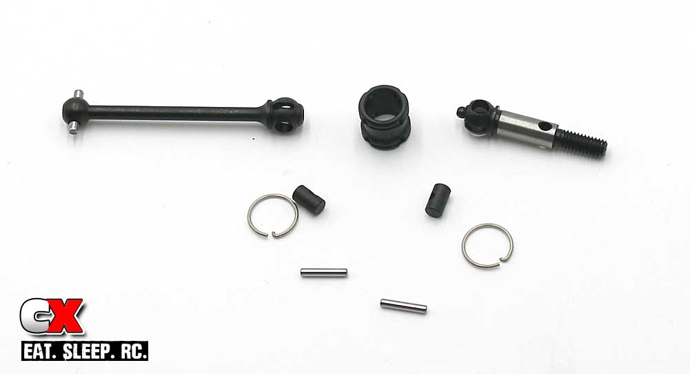
Build a pair of front double cardan joints. Yes, two axle rings – double your fun.
Don’t forget the Anti-Wear Grease.
Step 15:
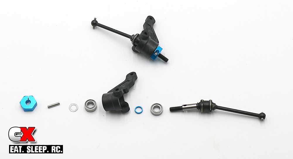
Assemble the left and right steering arms.
Step 16:
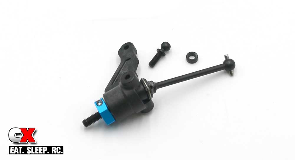
Attach the 8mm ballstud and spacer.
Step 17:
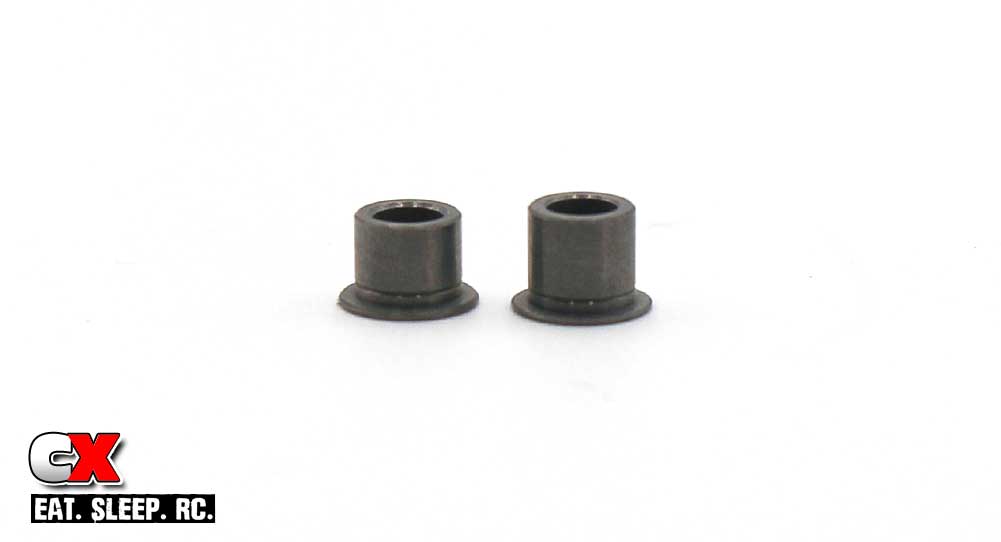
These two little guys will be used in the next step. This is to show you that they are different heights; the short one goes on top, the tall one goes on the bottom.
Step 18:
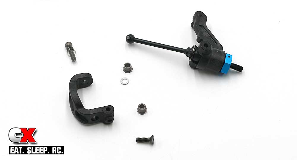
And here’s the assembly. I would suggest installing the bottom 10mm screw first to hold everything in place before attempting the upper 9mm ballstud.
You’ll also want to make a 2.5mm hole in the bottom of the caster block for the set screw in Step 21.
Step 19:
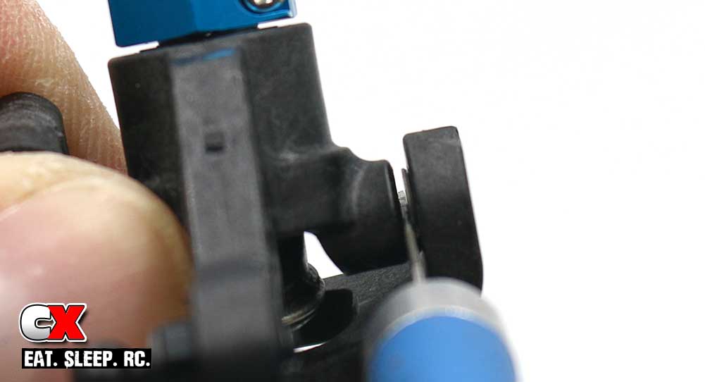
Now, here’s the tricky part. We need to slip a .5mm spacer into this gap, but doing that and installing the 9mm ballstud (and spacer) is a bit difficult with only two hands. Oh, and chubby fingers don’t help.
So, my solution was to wedge an Xacto knife in the space (to keep the 3.9mm flanged tube out of the way), slide the .5mm shim into place and then install the 9mm ballstud. Wah-lah – success.
I’m not going to lie – there was a bit of cussing going on prior to this solution.
Step 20:
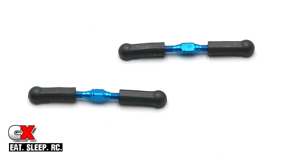
Build a pair of camber links.
Step 21:
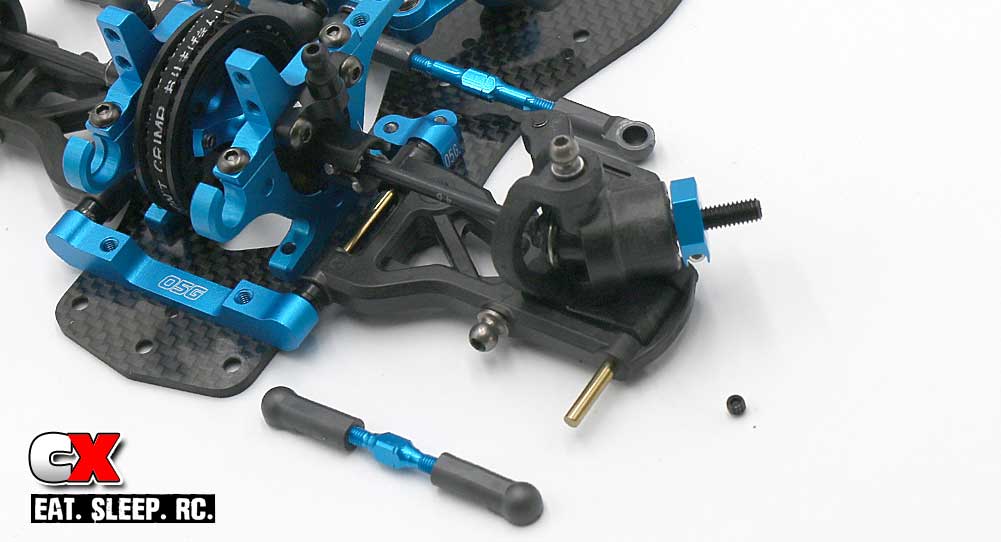
Attach each steering assembly to the front arms. Make sure the flat spot on the hinge pin faces down so the set screw can catch hold of it.
Step 22:
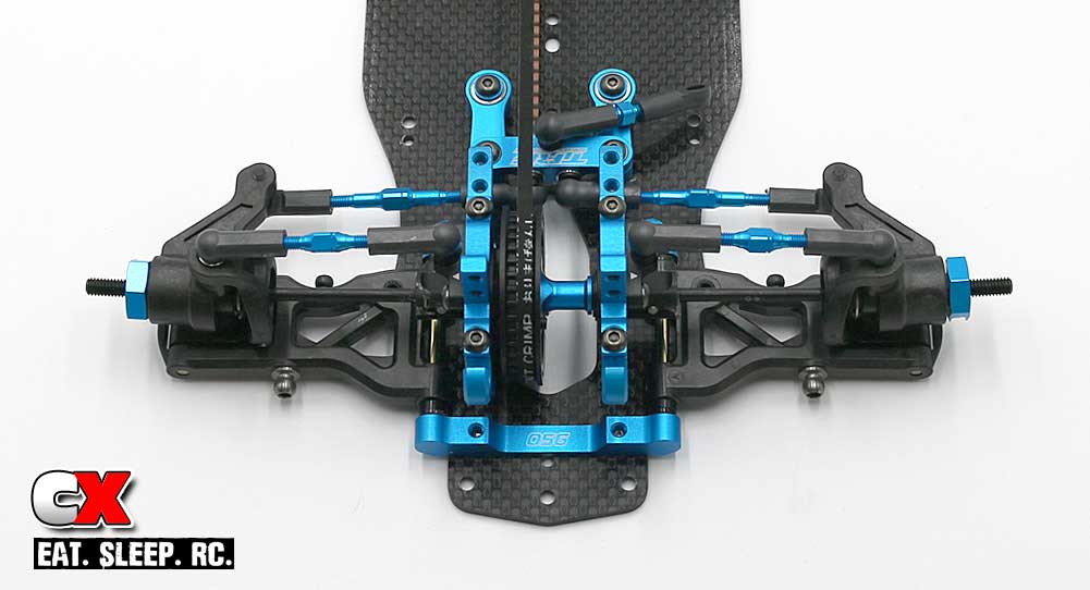
Front suspension done! Swing all 4 arms up and down to make sure they move freely.
Longest step so far, but it’s beginning to look alot like a Touring Car! Let’s roll to Step 6 and attach the Anti-Roll Bars!
Tamiya TRF419XR Online Build – Part 6
Like any good Touring Car, the Tamiya TRF419XR comes equipped with a front and rear anti-roll bar. I’m sure the kit bars work fine with additional bars available for tuning.
Build Notes:
• Nothing special.
Step 1:
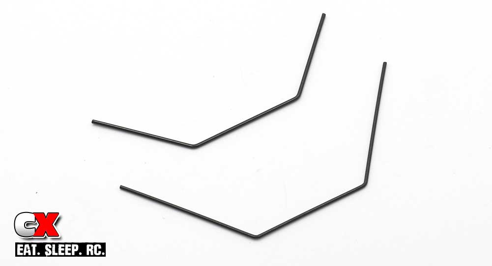
First thing – be aware that the bars are different sizes. The one on the top is for the front, the one on the bottom is for the rear.
Step 2:
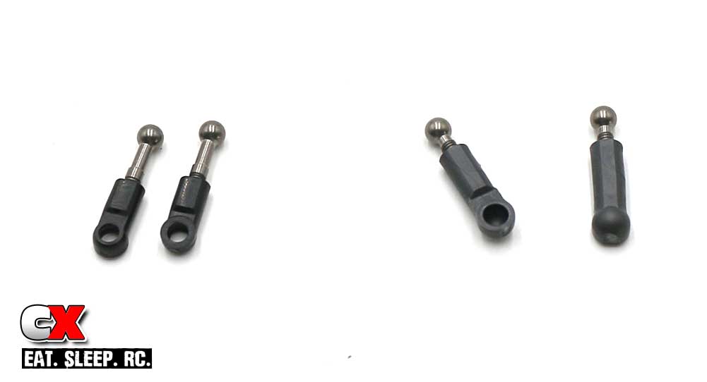
Assemble the standoffs – these will connect the bars with the arms. Pay attention to the ballcups uses as well (there are several different ballcups included with the TRF419XR).
Step 3:
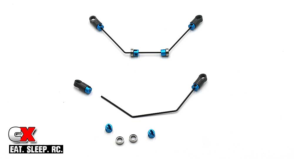
Assemble the bars. You don’t need to tighten down the rod stoppers just yet; we’ll do this in a later step.
Step 4:
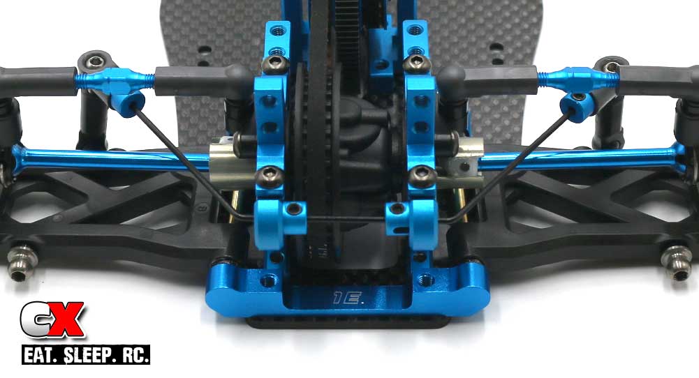
Install the rear bar. Slide the bearing into the bulkheads followed by the rod stoppers. Cinch the 2.5mm setscrew down in the rod stopper until hits the bar. Do not overtighten.
Pop the standoffs onto the bar and connect it to the arm.
Step 5:
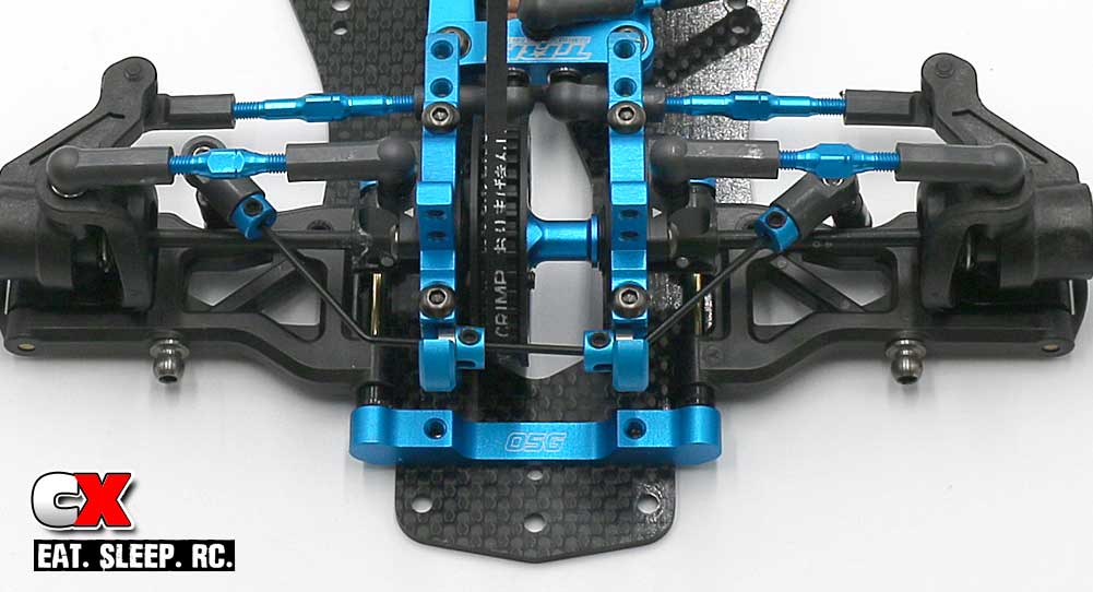
Same with the front.
Another quick and easy step – anti-roll bars installed! Set your TRF419XR aside and let’s get going on Step 7 – the Shocks!
Tamiya TRF419XR Online Build – Part 7
The TRF419XR includes a full set of Tamiya’s incredibly smooth TRF Super Short Big Bore Shocks. In addition, the XR comes with low-profile carbon shock towers to help keep the CG as low as possible.
Build Notes:
• Shocks require fluid. Fluid can be messy. Have a clean work area and some rags available to help with any mess that might occur. A shock stand will also be beneficial here as well.
Step 1:
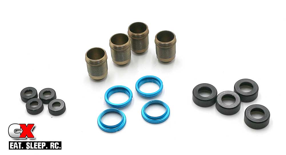
Before we start, completely disassemble the shocks and separate all the parts.
Step 2:
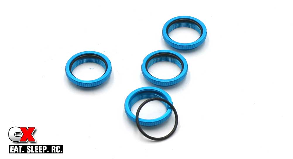
Slip the black o-ring into the collars. Doing this now will ensure you have fluid-free fingers; trying to do this with shock oil on your mitts could cause a mental breakdown.
Step 3:
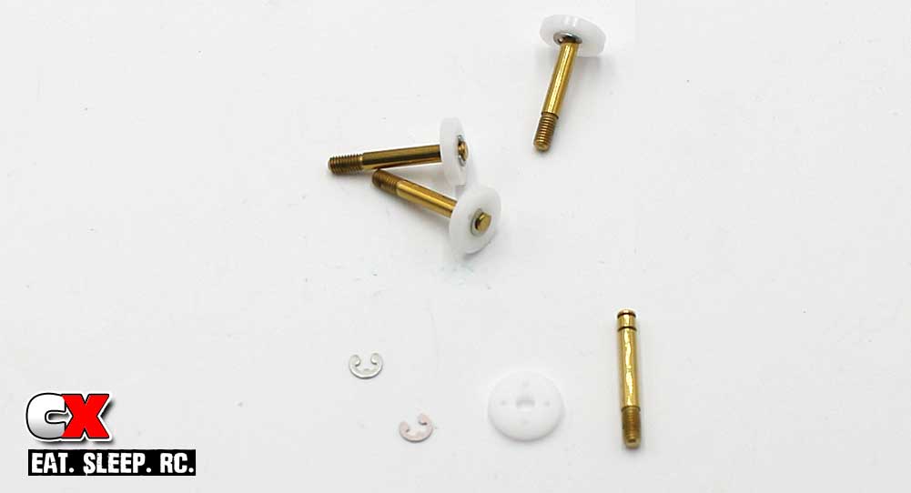
Attach the pistons to the shock shaft.
Step 4:
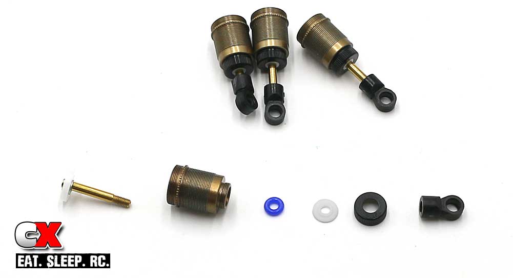
Slide the shaft assembly through the shock body. Place a small drop of fluid onto the threaded part of the shaft and slide an o-ring and rod guide on. Make sure the ‘lip’ on the rod guide faces down.
Once on, thread the rod guide cap onto the bottom of the shock body. The ‘lip’ on the rod guide should feed through the rod guide cap.
Finally, thread the shock eyelet onto the shaft. Make sure all 4 shocks have the same gap between the bottom of the shock body and the top of the shock eyelet.
Step 5:
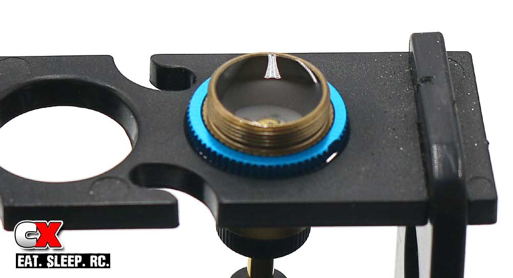
Thread the collar onto the shock. Fill the shocks with fluid. Pump the shaft up and down a few times to release any bubbles out from under the piston and set aside. We want all the bubbles to dissipate.
Step 6:
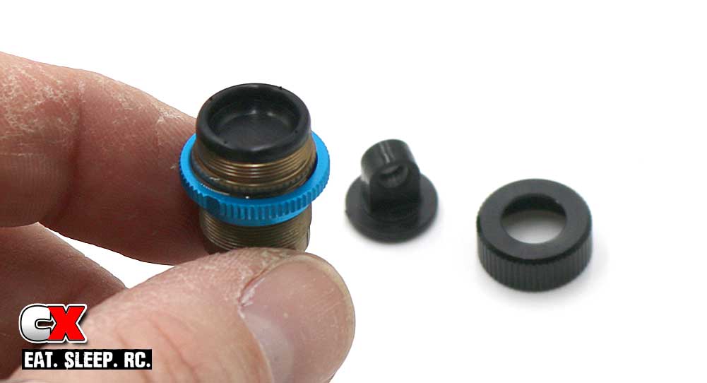
Refill with fluid until it is slightly crowned inside the shock, then set the bladder on top, forcing any extra oil out of the shock. Set the plastic shock top into place, then thread on the aluminum shock cap.
Plunge the shaft a few times to make sure the shocks don’t bind.
Step 7:
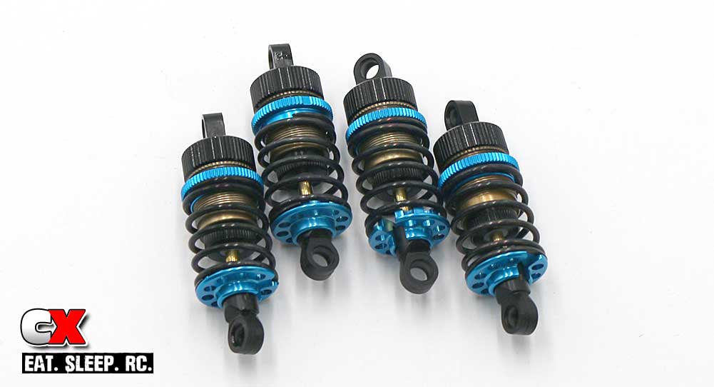
Install the shock spring and bottom spring retainer. Thread the collars down until they come in contact with the spring.
Step 8:
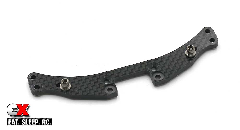
Assemble the rear shock tower. Note the orientation.
Step 9:
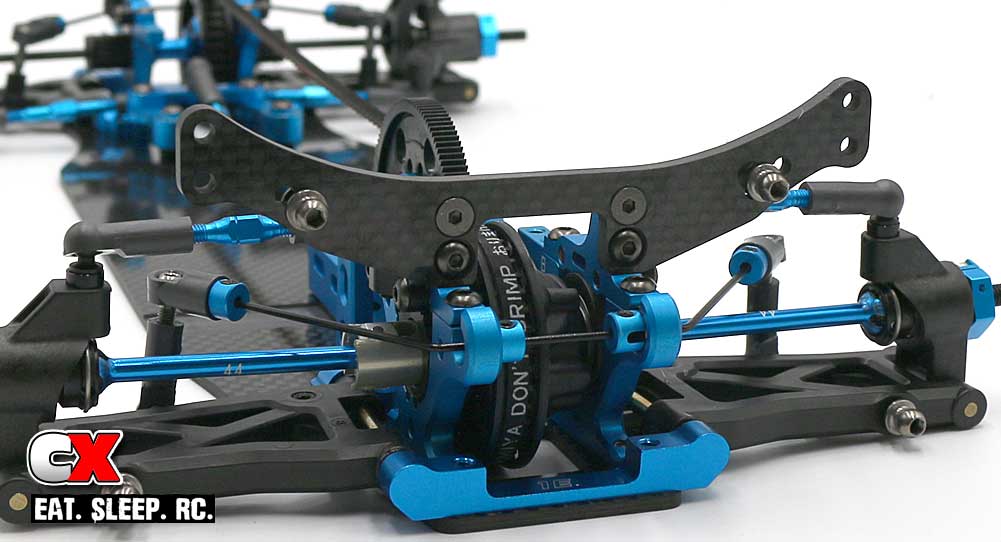
Attach the rear tower assembly to your car.
Step 10:
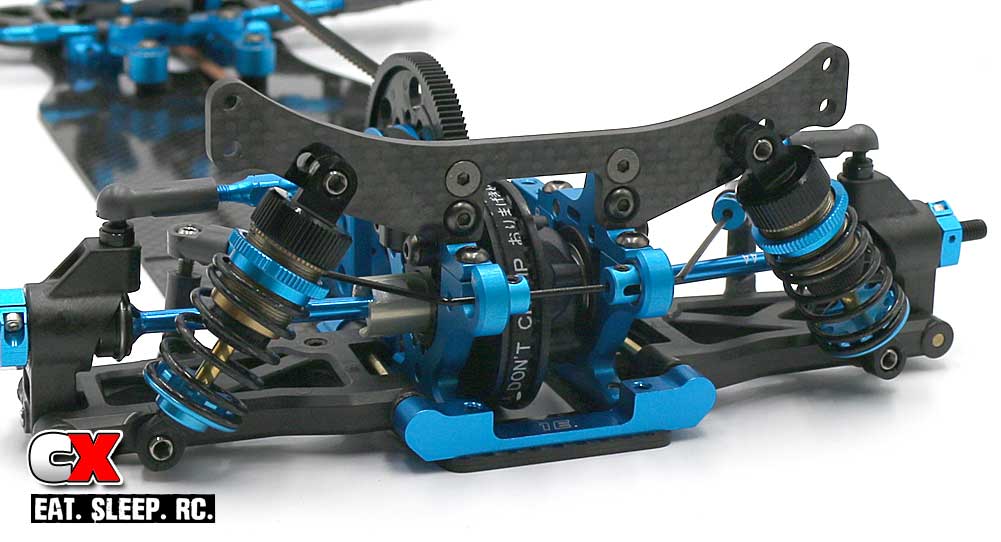
Attach the rear shocks.
Step 11:
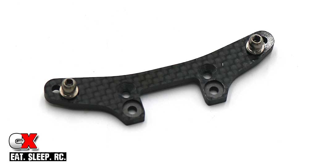
Assemble the front shock tower. Note the orientation.
Step 12:
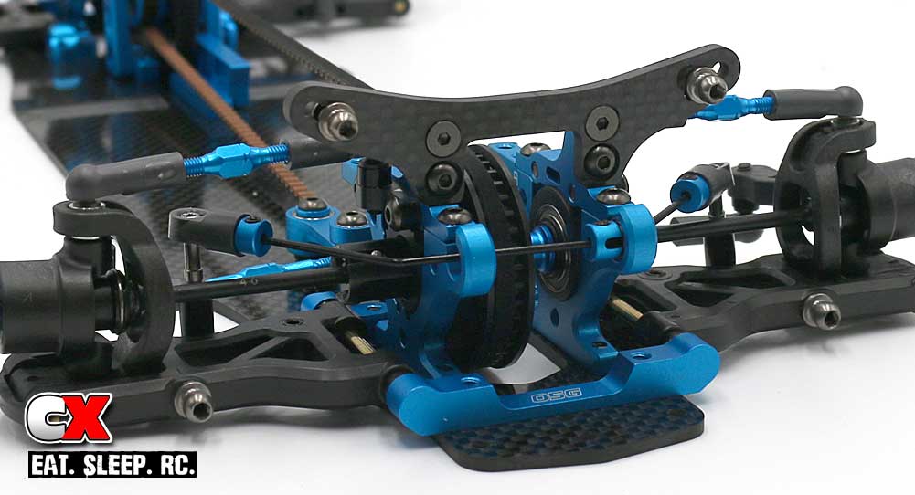
Attach the front tower assembly to your car.
Step 13:
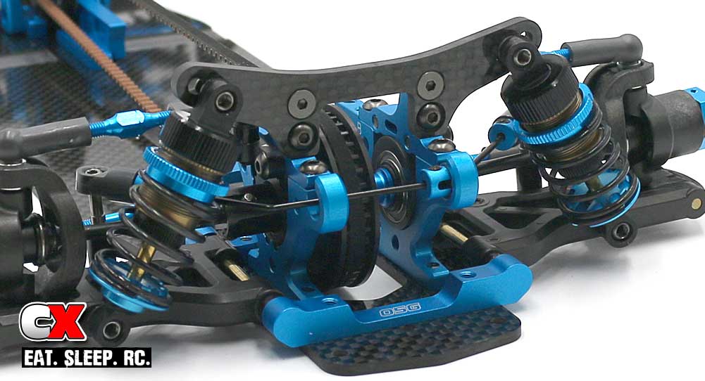
Attach the front shocks.
We’re using the kit-suggested mounting locations for the shocks, however we’ve started with 35wt fluid. This might change if the car feels lazy around the track.
Tamiya TRF419XR Online Build – Part 8
The final assembly has us installing the top deck, bumper, battery holders and the electronics.
Ok, on to the build!
Build Notes:
• The TRF419XR allows several different options at this point; different center braces, weights, battery holders, etc. These spare parts are in a separate bag, so don’t forget to pull them out to see the options.
• One thing to note – the stock spur gear that comes with the TRF419XR is not suitable for stock class racing. Top top it off, the spur gear mounting setup is a little odd as well, meaning not just any spur gear will work. I found that the Panaracer-Xenon spur gears work the best.
• Since your electronics will probably not match what I have, I left the install of these out of the build. It’s pretty straightforward, however, so you shouldn’t have a problem installing yours.
Step 1:
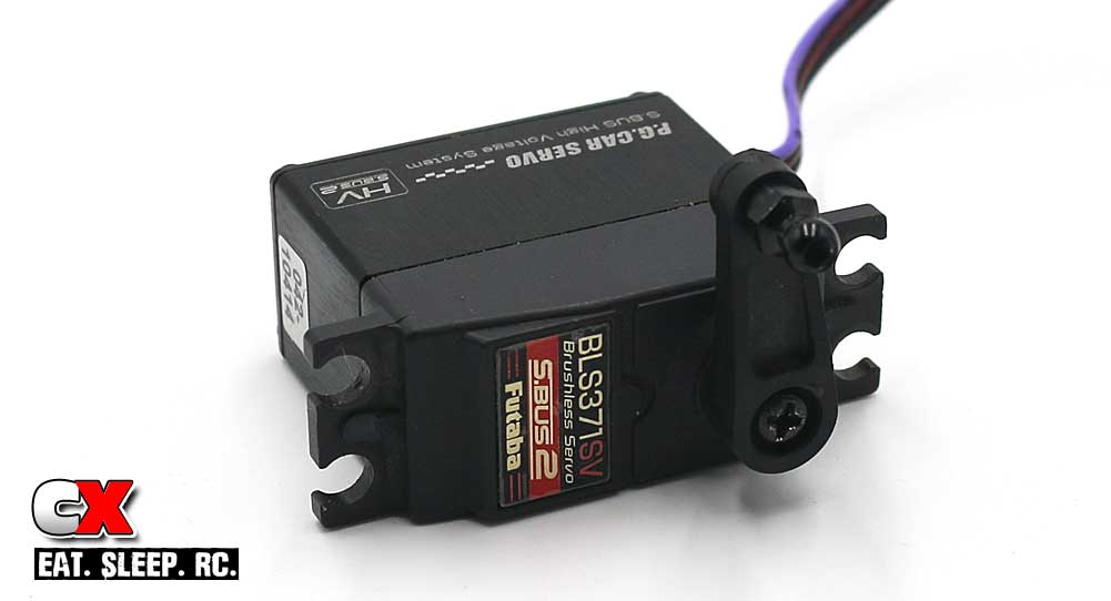
The first step is to assemble the servo horn and attach it to the servo. You can use the included servo saver setup or, like I did, attach a standard horn. I’m not to keen on the Tamiya servo savers – they seem to flex a bit too much for me.
Step 2:
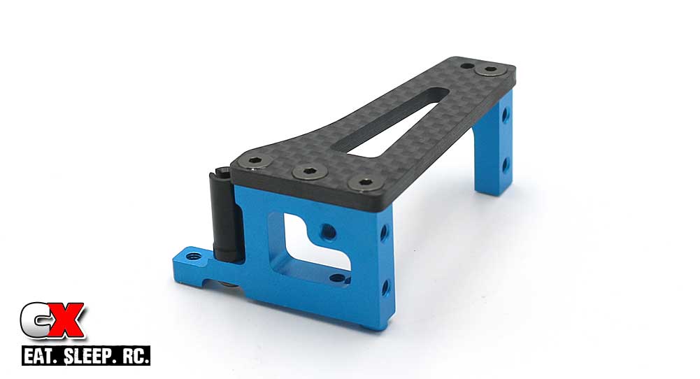
Assemble the servo mount. Blue threadlock is suggested here.
Step 3:
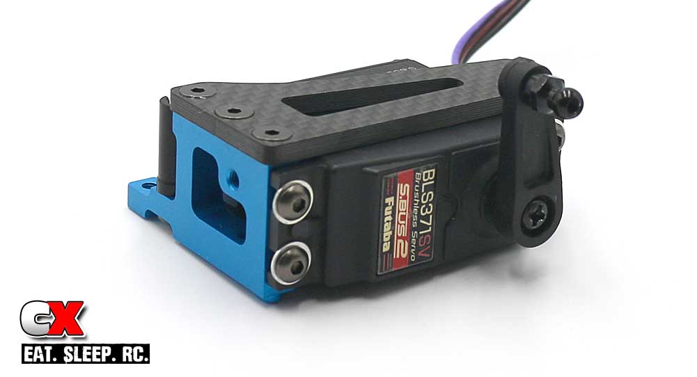
Attach the servo to the mount. Blue threadlock is suggested here as well.
Step 4:
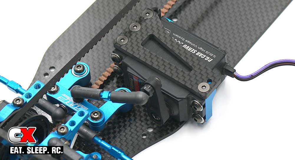
Attach the mount to the chassis. You’ll notice it’s only attached on one side – this is an example of a floating servo mount. This helps retain the correct tweak on both sides of the car. Don’t forget to pop the drag link onto the servo horn.
Step 5:
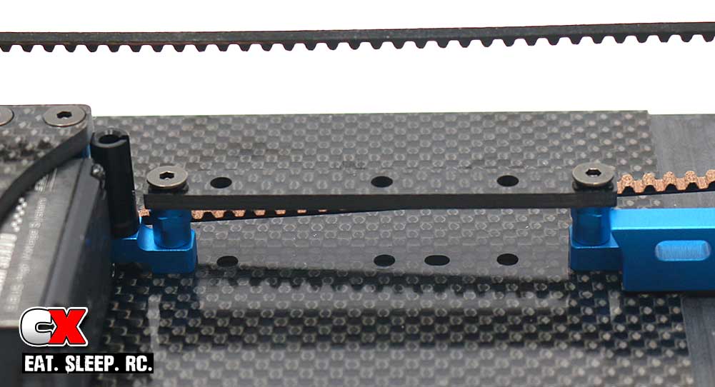
Here is where you’ll have some options; I went with the carbon brace as a starting point. I also attached the weight in the center, however I chose to do it after I had already built the car. (See the end of the manual for chassis rigidity options).
Step 6:
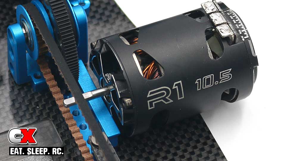
Attach the motor. I will be running in the 17.5T class but, since my motor hadn’t arrived at the time of the build, I dropped a R1 Wurks 10.5T in for show.
Step 7:
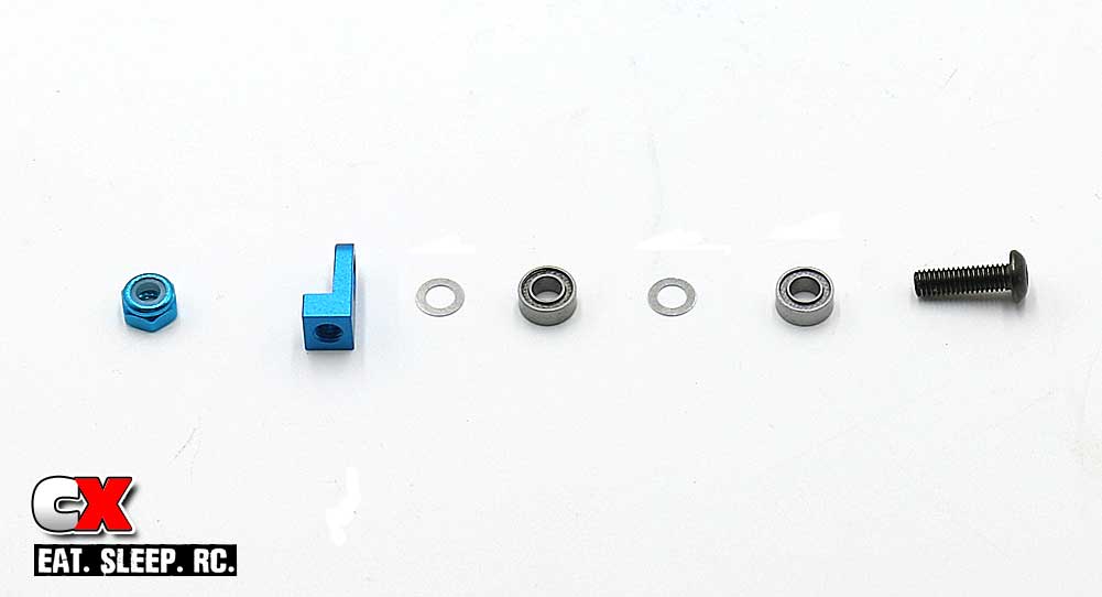
Assemble the belt tensioner.
Step 8:
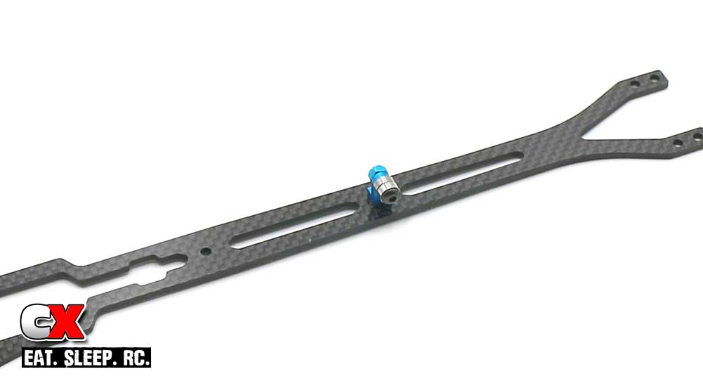
Attach the tensioner assembly to the top deck.
Step 9:
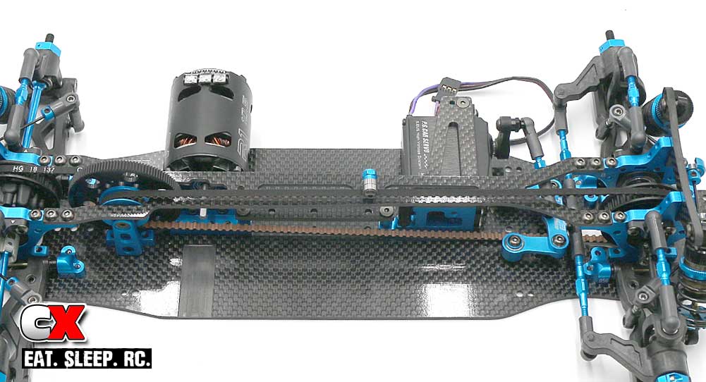
Attach the top deck. I would NOT recommend using blue threadlock on these screws.
Step 10:
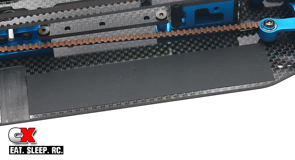
Attach the battery pad. It’s a bit long so I cut it down a little to fit.
Step 11:
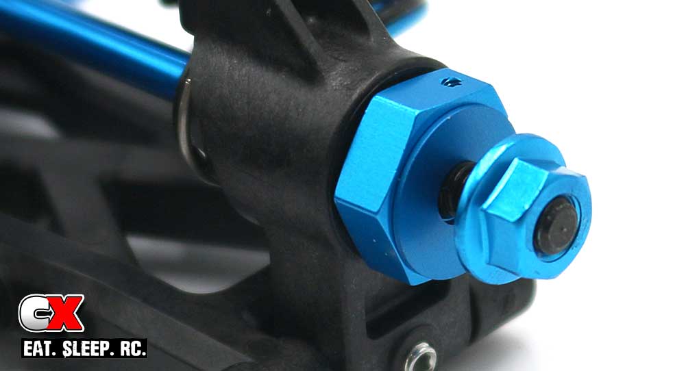
Slip a wheel spacer onto the axle followed by the serrated nut. The spacers can be left off to help tune the width of your TRF419XR.
Step 12:
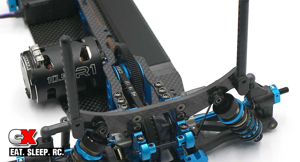
Attach the rear body posts.
Step 13:
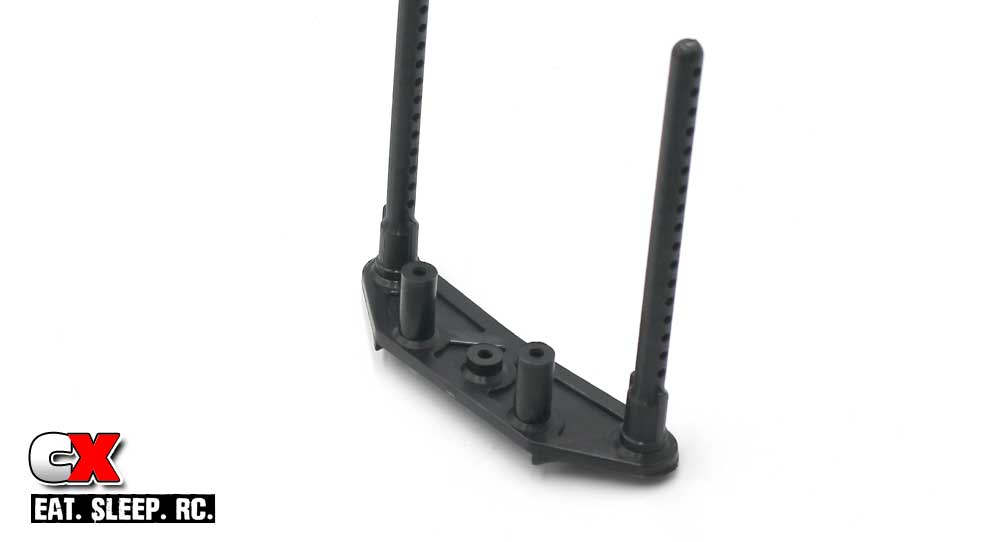
Attach the front body posts to the front bumper.
Step 14:
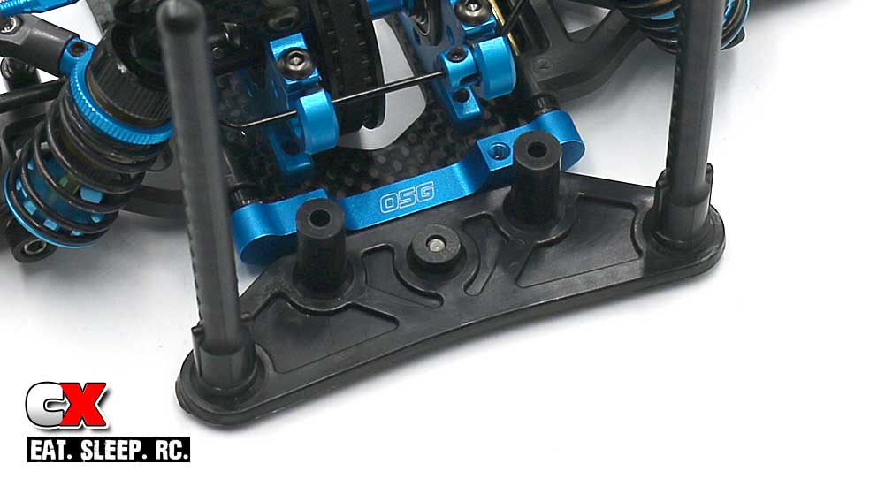
Attach the front bumper assembly to the chassis.
Step 15:
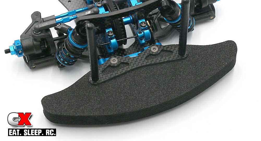
Slide the foam bumper into place, then the carbon bumper mount. Secure with the 2 8mm screws.
Step 16:
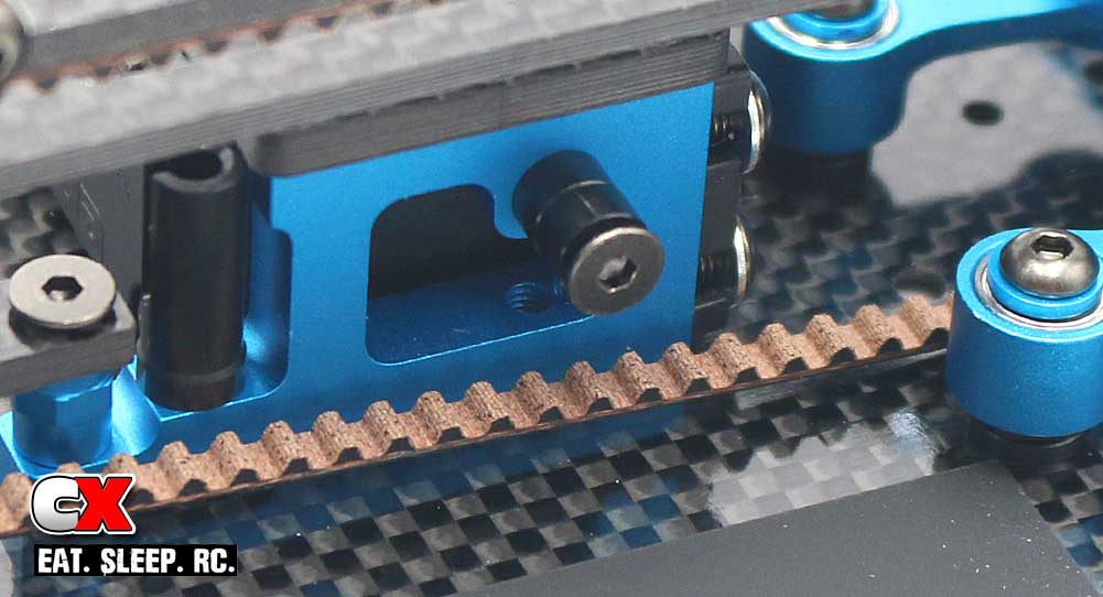
Install the battery bumper. This can be adjusted (more or less spacers) to move the battery in or out.
Step 17:
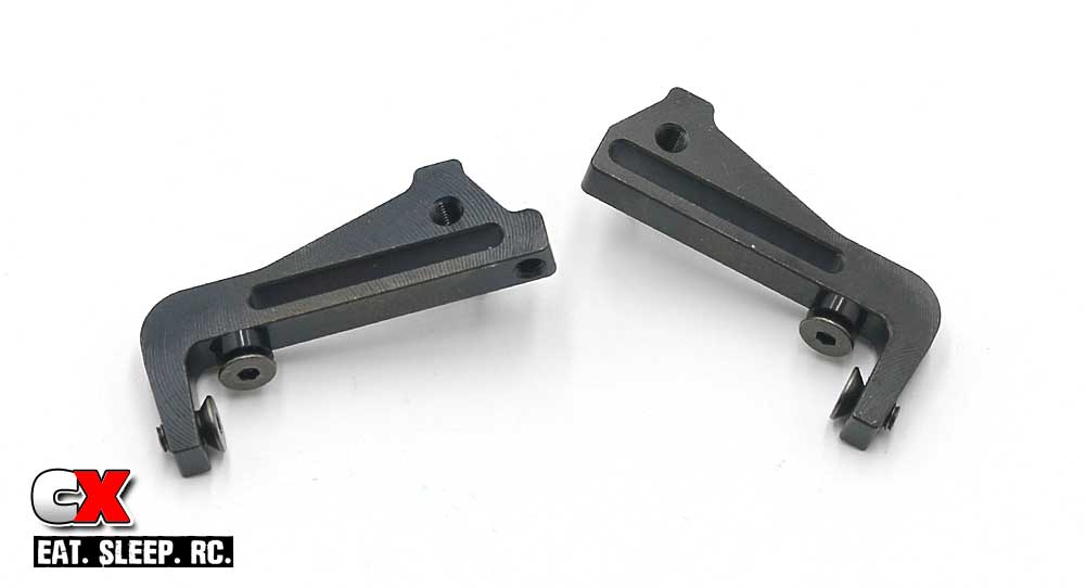
Assemble the 2 battery holders. These additional screws can be adjusted (more or less spacers) to move the battery in or out or front to back.
Step 18:
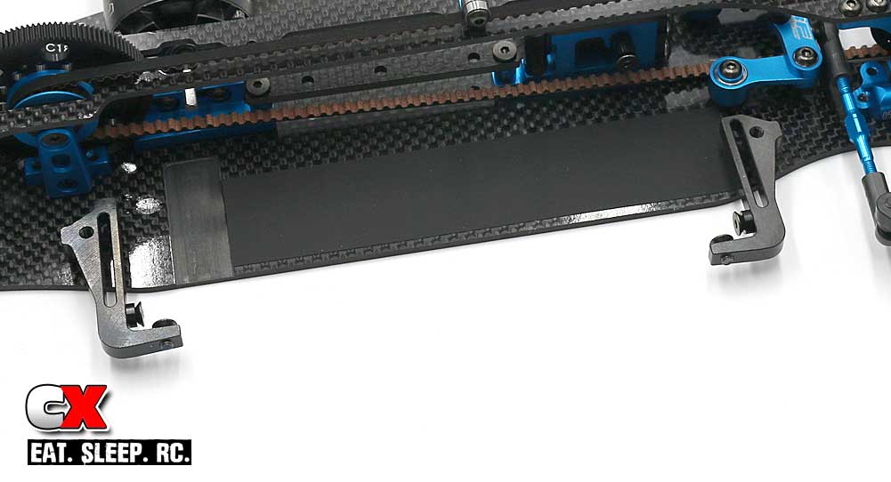
Attach the battery holders to the chassis.
And, just like that, you have a completed Tamiya TRF419XR Touring Car! Now install your electronics, mount that body and get to some racing!

