
RC4WD Trail Finder 2 LWB Trail Truck Online Build
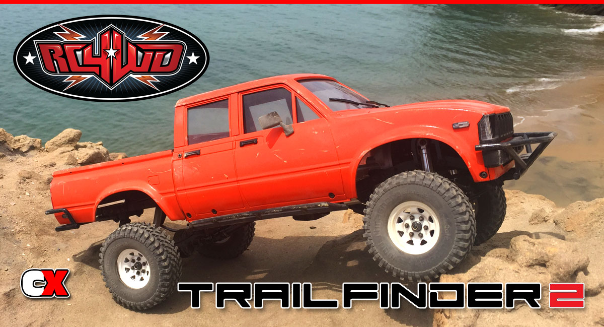
I’ve always been a fan of RC4WD’s Trail Finder 2 truck; the scale realism, aftermarket support and, of course, the bad-ass Toyota body. When the LWB (Long WheelBase) version hit our shores, I knew it was time to add one to my collection; I’ve never had a hard body vehicle before and, well, this one is simply gorgeous!
I also decided to do a full build on this truck as well – from opening the box to it’s maiden voyage – and here it is. Hopefully this will help you with any build issues you might have.
RC4WD Trail Finder 2 LWB Build – Part 1
The first part of our RC4WD Trail Finder 2 LWB Trail Truck build is assembling the frame rails, cross bracing and front shock hoops.
Build Notes:
• Pay close attention to the orientation of both frame rails. There are a lot of holes on each and you might get a little mixed up as to which is the left and right.
• Have some blue threadlocker available and use a small dab on any screws that thread into aluminum parts.
Step 1:
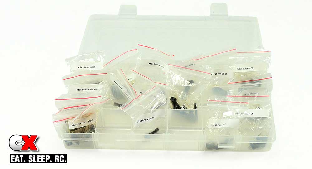
The first step is screw organization – the screws used in this build do not come attached to ‘each step’ like most kits. So, before we get started, I suggest organizing all the screws to make them easier to locate. I opened each bag and placed them in a small, multi-pocket plastic container to keep them cataloged. Since RC4WD has printed the sizes of the screws on each bag, I suggest keeping the screws IN the bags while in the container.
Now, on to the build!
Step 2:
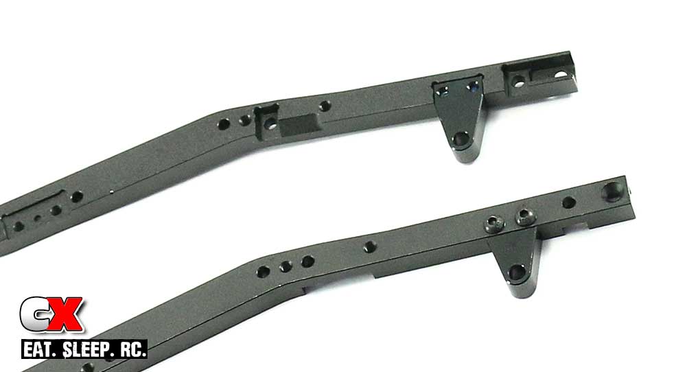
Start by attaching the rear-most leaf spring hangars onto the rear part of the chassis. Pay close attention to the holes in the frame rails so you know which is the rear.
Step 3:
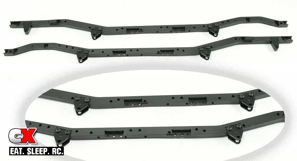
Now attach the inner leaf spring hangars to the chassis as shown (the inset shows a little closer view for orientation purposes).
Step 4:
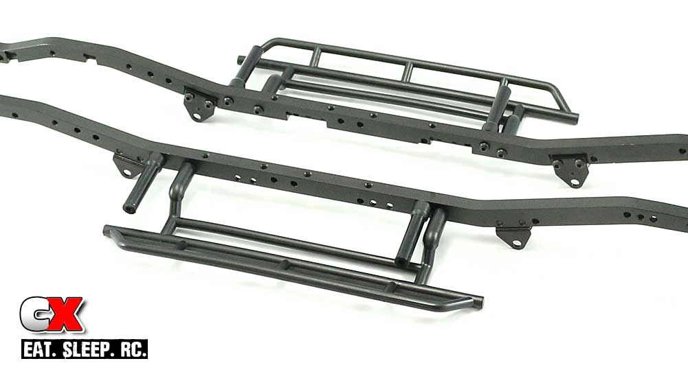
Attach both the rock sliders and body mounts to the frame rails. Since the screws are going into plastic, no threadlocker is required.
Step 5:
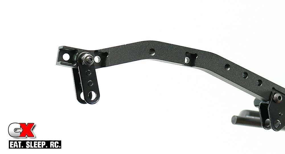
Moving to the front, attach the swinging leaf spring mounts by sliding the shouldered screw through and securing with the M3 locknut. These need to swing freely; if not, make sure the shouldered screws goes all the way through both ‘swingers’.
Step 6:
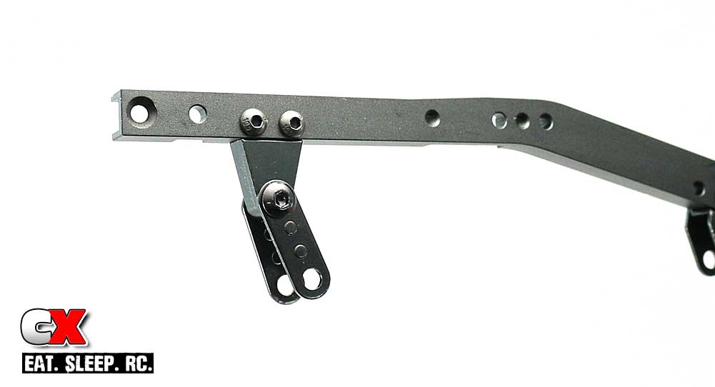
Move to the rear of the TF2 rails and attach the swinging leaf spring mounts like you did in Step 5. Again, these need to swing freely. Complete Steps 5 and 6 on both frame rails.
Step 7:
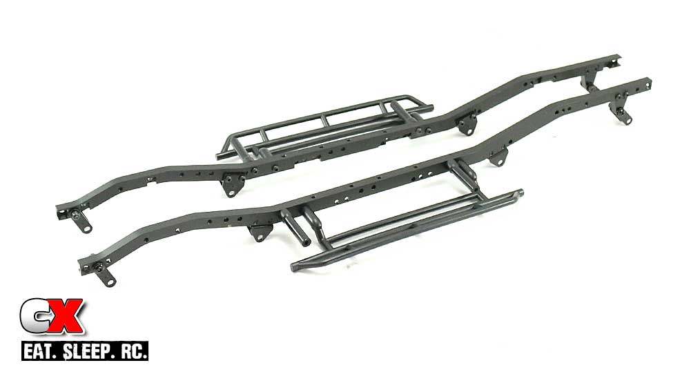
Your completed rails should look like this.
For the next couple steps, we’re going to be working with the right-side rail (the upper one in the picture). Match up your rails to the picture and move the bottom one (left-side rail) off to the side. We’ll get to it in a moment.
Step 8:
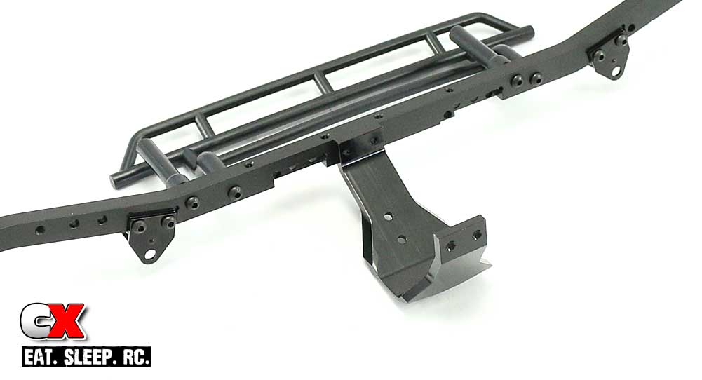
Attach the center skid to the right-side rail. Note the orientation of the skid.
Step 9:
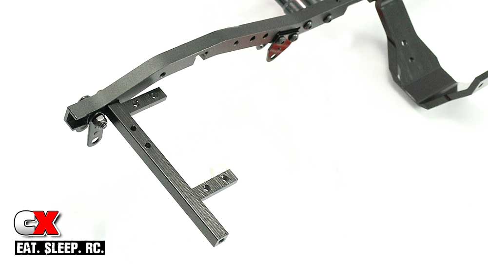
Move to the front and attach the cross brace/servo mount. Again, note the orientation.
Step 10:
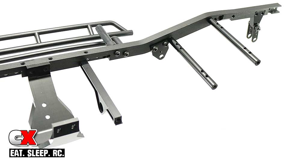
Move to the rear of the frame rail and attach the 3 cross braces. Unfortunately my picture is a little hard to see, but the front-most brace should have the longer ‘arm’ pointed toward the rail (the manual pic is a little clearer). On the back 2 cross tubes, apply a small dab of blue threadlocker but don’t tighten the screws all the way down just yet. You’ll understand when it comes time to attach the radio box in a later step.
Step 11:
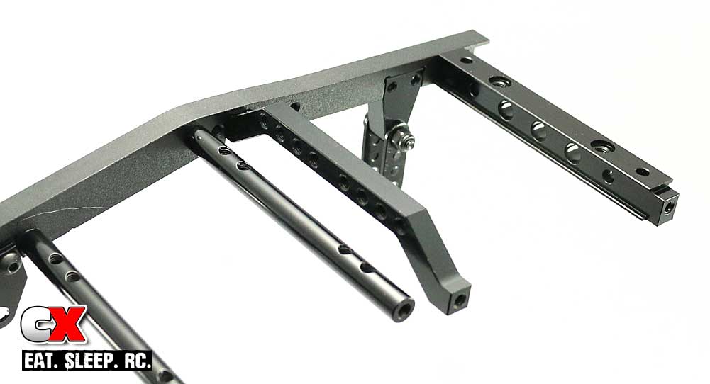
Attach the hoop cross brace and rear most body mount brace now.
Step 12:
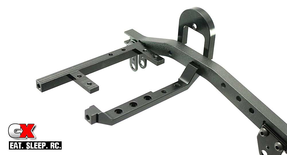
Move back to the front and attach the right side front shock hoop, using the cross brace to retain the rearmost screw. Note the orientation of the cross brace (see the notch).
Step 13:
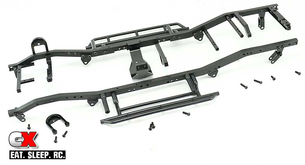
We’ve completed the right side frame rail – now button up this step of the build by attaching the left side frame rail using the same screw lengths from the previous steps.
Step 14:
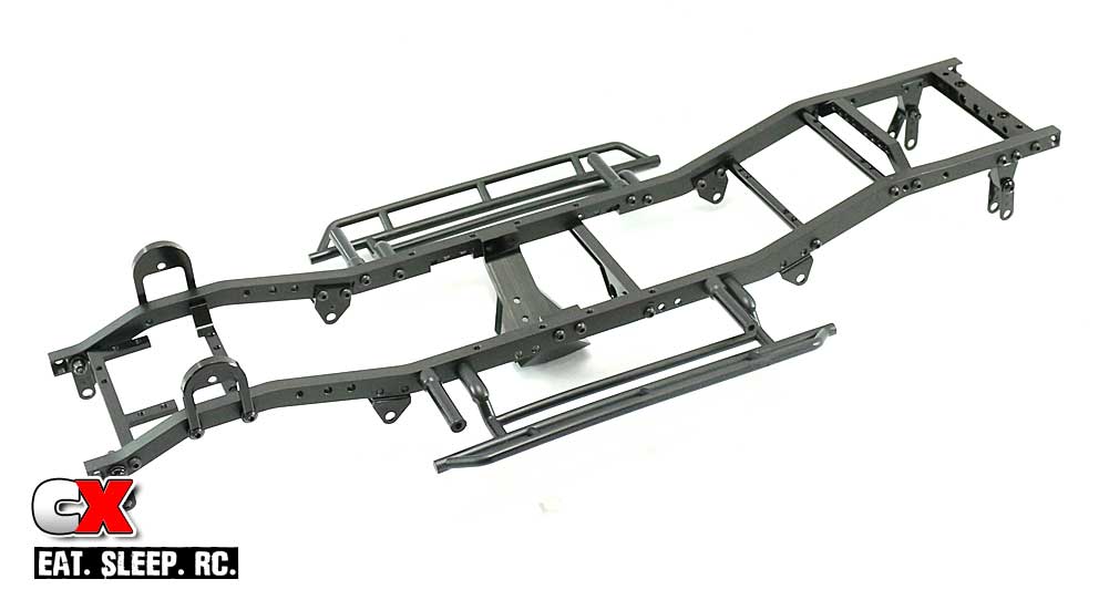
Congrats on completing Build Step 1! Your final frame rail setup should look like this!
Alright, great job. Just so you know, this was probably the longest step in the build so, go get a drink, a cookie and let’s move on!
RC4WD Trail Finder 2 LWB Build – Part 2
The next step in our RC4WD Trail Finder 2 Build revolves around the radio pad and rear body mounts.
Build Notes:
• Have some blue threadlocker available and use a small dab on any screws that thread into aluminum parts.
Step 1:
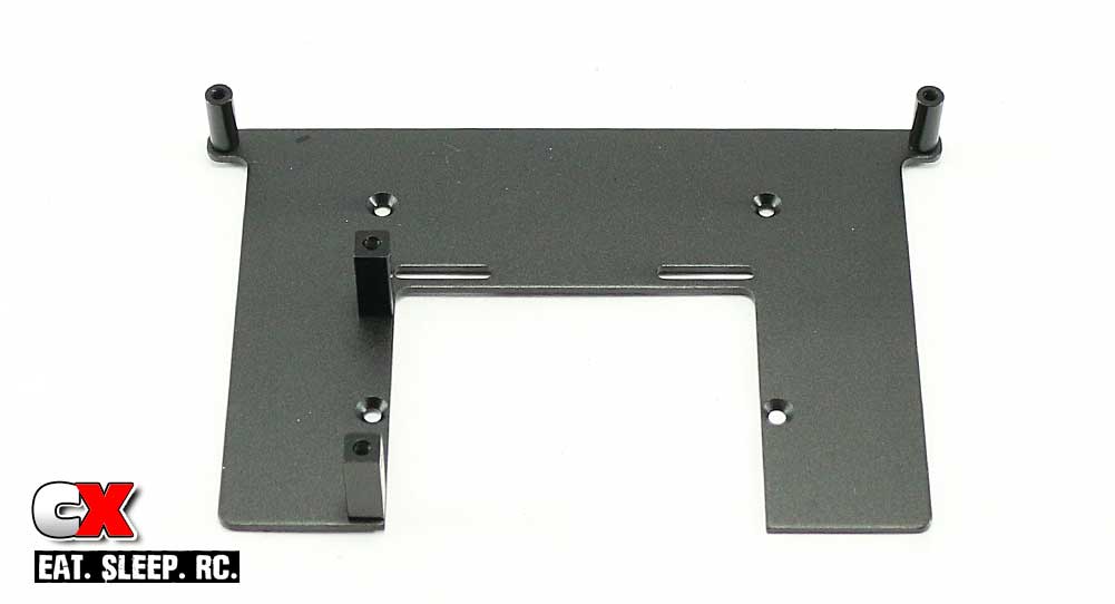
Assemble the radio pad as shown by attaching the two aluminum standoffs and the pair of servo mounts.
Step 2:
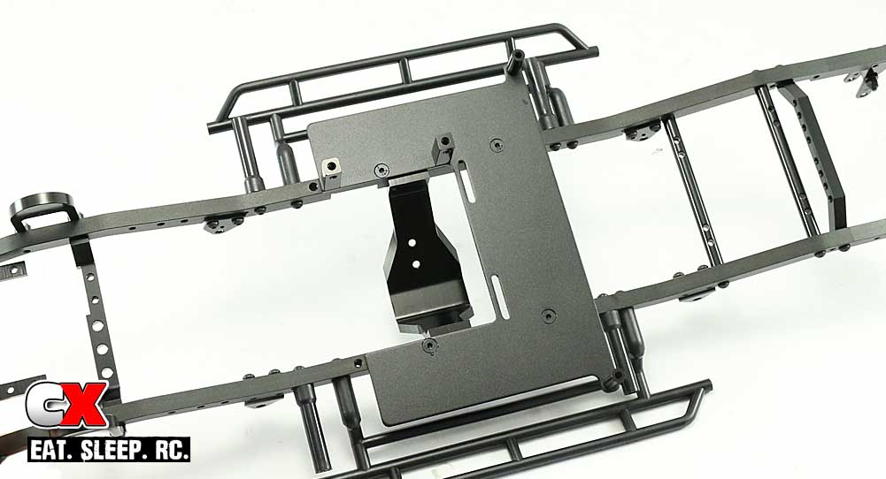
Set the radio pad in place on your completed frame rails and screw into place. You might notice that there are two sets of holes here to move the radio pad; use the rearmost set of holes.
Step 3:
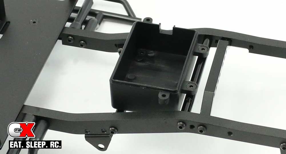
Attach the radio box. If you left the screws loose from Step 10 in Part 1 of the build, you’ll be able to rotate the tubes to line up the holes better. Once you have the box attached, tighten down the 4 tube screws.
Step 4:
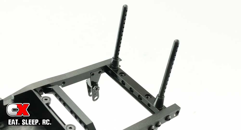
Attach the rear body mounts to the cross brace as shown. Note the orientation of the body mount holes; the body pin holes should be facing the sides of the rails.
Step 5:
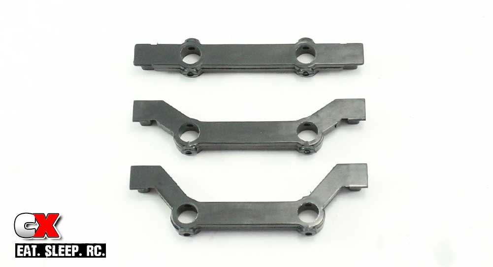
RC4WD has included 3 different bumper mounts with the TF2 LWB; the top mount is not used, the middle one is for the rear of the TF2 and the lower one for the front. Throw the top one back in the box, grab the middle one for this step and set the lower one off to the side for later.
Step 6:
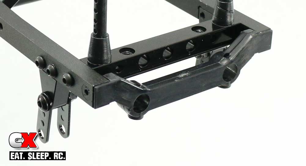
Attach the bumper mount.
There ya go – 6 easy steps and we’re almost done. Ok, not really, but it’s beginning to look more like a scale rig now, right? Let’s move on to the gearbox!
RC4WD Trail Finder 2 LWB Build – Part 3
The next step in our RC4WD Trail Finder 2 build is attaching parts to the gearbox. The gearbox itself comes pre-assembled so there isn’t really anything to do except attach the mounts and drop it in place.
Build Notes:
• Before installing the gearbox, I suggest you rotate the spur gear and plunge the two-speed shifting fork a few times to make sure everything works. I didn’t have a problem with mine, but things happen and it’s better to find out before you install it than after.
• Have some blue threadlocker available and use a small dab on any screws that thread into aluminum parts.
Step 1:
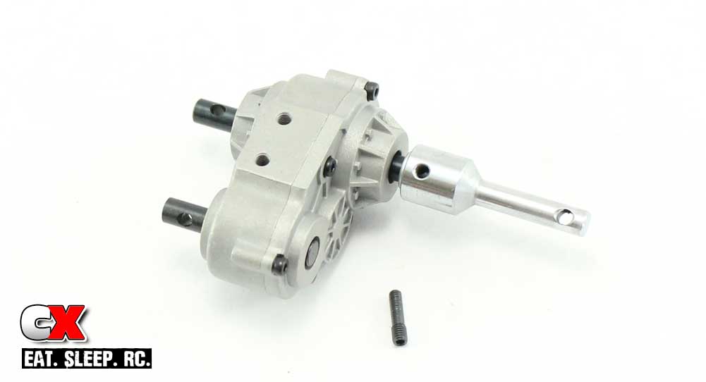
Prep the transfer case by installing the output shaft and threaded cross pin.
Step 2:
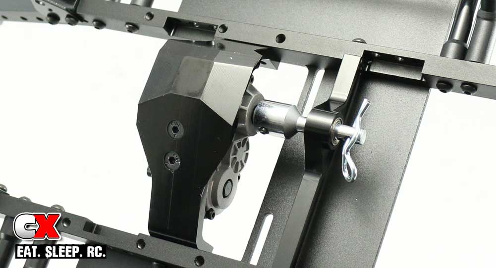
Feed the output shaft through the mount and attach the gearbox to the skid plate. Once in place, slide the bearing over the output shaft as shown. The bearing fit isn’t super tight, so chances are it’s going to slip out during the rest of the build – mine did. I used a spare body clip I had lying around and fed it through the output shaft to keep the bearing secure.
Step 3:
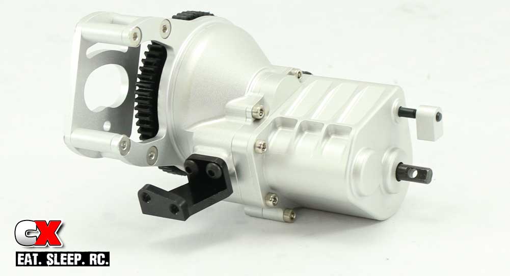
Attach the left-side motor mount.
Step 4:
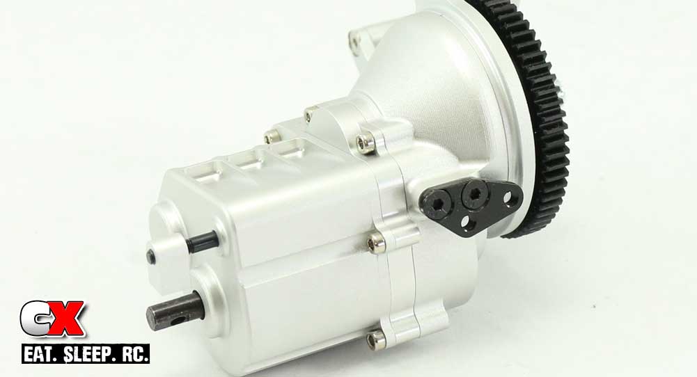
Attach the right-side motor mount.
That’s it for this step; set the gearbox aside for a later installation. Time to assemble and install the suspension!
RC4WD Trail Finder 2 LWB Build – Part 4
In this Step, we’ll be assembling and attaching both axles to the RC4WD Trail Finder 2. The TF2 uses a leaf spring suspension and internally-sprung shocks for damping. Very cool looking – very realistic.
Build Notes:
• The shocks require oil before attaching them to the TF2, so have some towels ready for cleanup. Fill them slowly to minimize the mess.
• Have some blue threadlocker available and use a small dab on any screws that thread into aluminum parts.
Step 1:
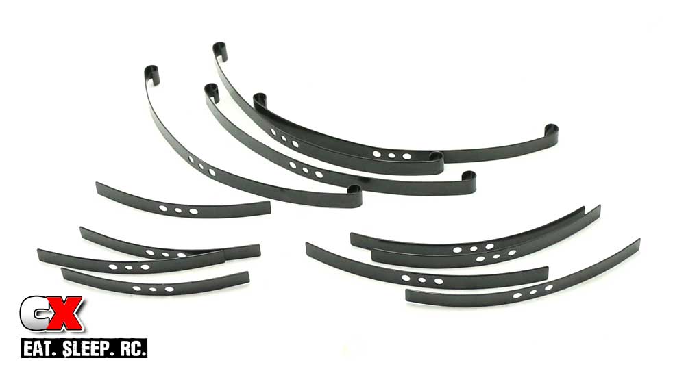
Before we start attaching the leaf springs, I suggest pulling them out and matching up the sizes. There are 3 different lengths, each adding additional stiffness to the suspension.
Step 2:
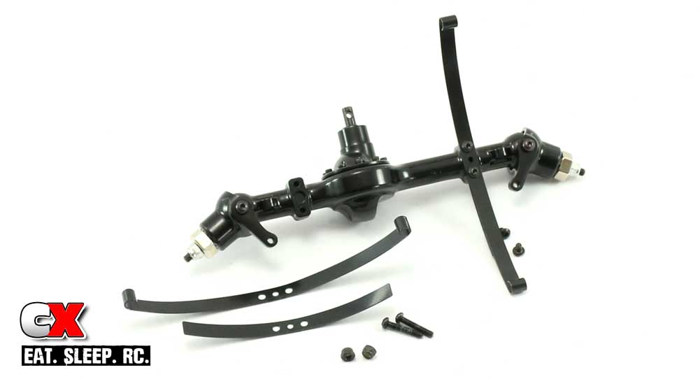
While the instructions suggest using all 3, I’m going to build my TF2 with just two springs per corner. This will allow a little more flex and articulation in the suspension for a better crawl.
The axle is held together with 4 shorty screws. To make the build a little easier, I suggest removing only 2 screws at a time and then attach one set of leaf springs.
Step 3:
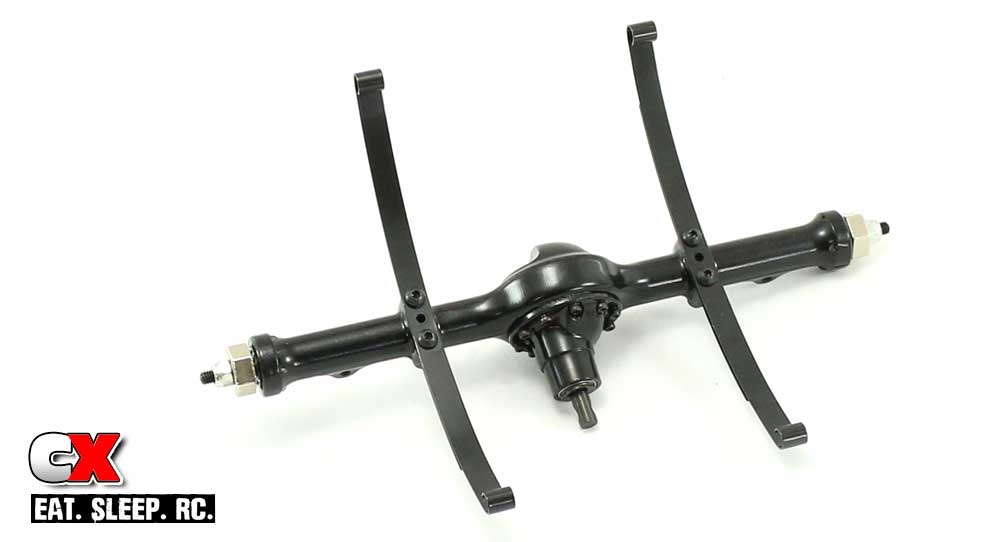
This is the completed rear axle; build the front axle the exact same way.
Step 4:
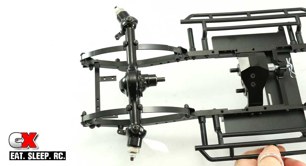
Carefully attach the front suspension to the shackles as shown.
Step 5:
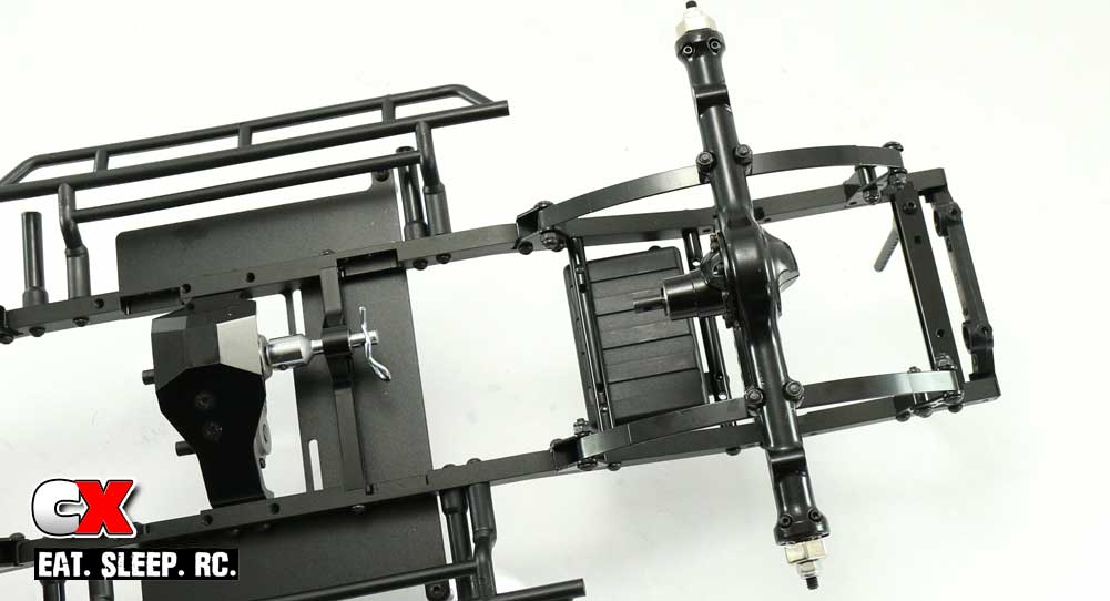
Carefully attach the rear suspension to the shackles as shown.
Step 6:
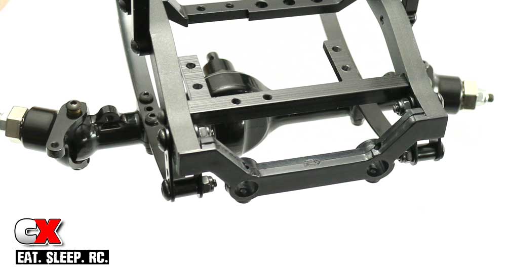
In Step 5 of Build Part 2, we set aside the front bumper mount – now it’s time to grab that and install it.
Step 7:
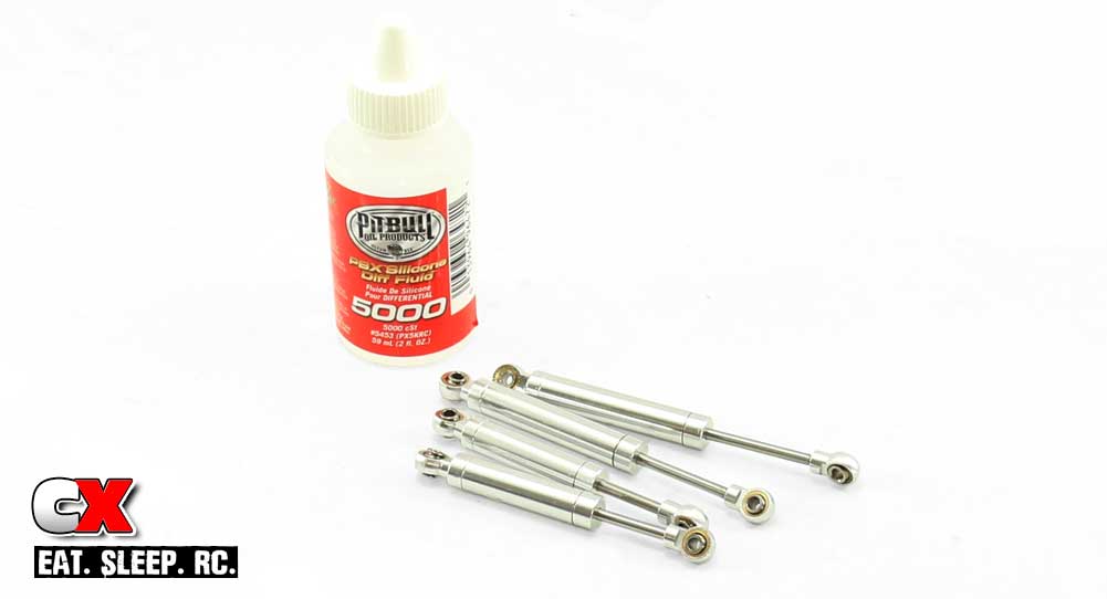
The TF2 shocks come pre-assembled in two different lengths (80mm and 100mm), however there is no oil in them. I did a little poking around and found that owners of this rig are putting 5000wt diff fluid into their shocks. This seems a bit thick to me but I’ll give it a go since others seem to have success with it. Again, fill these slowly and, after re-assembly, wipe off any excess oil.
Step 8:
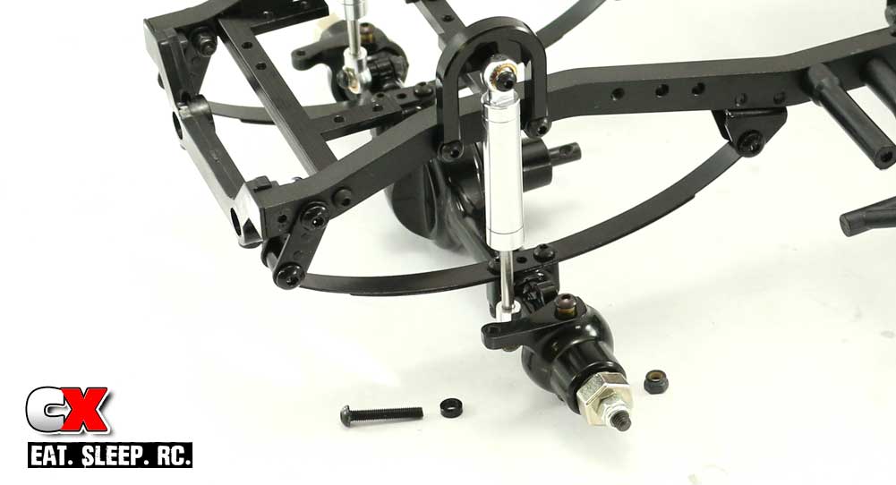
Attach the 80mm shocks (shorter ones) to the front (don’t forget the 2mm spacer on the bottom).
Step 9:
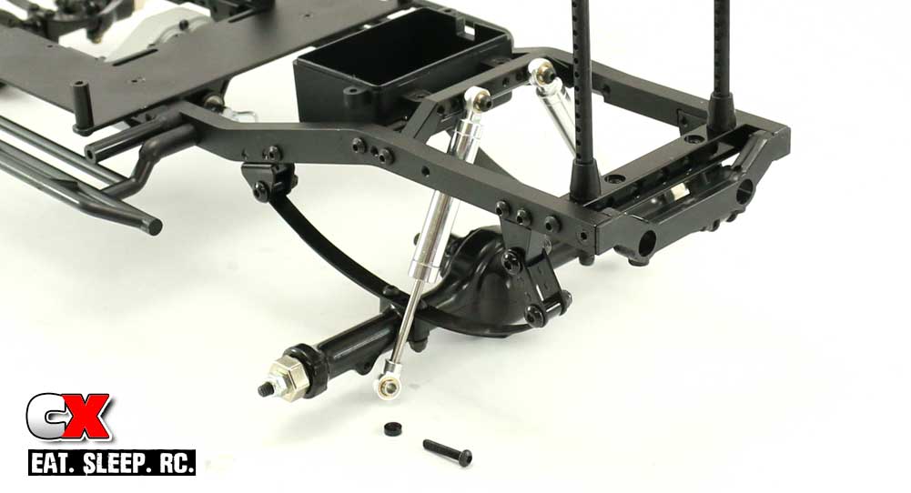
Attach the 100mm shocks (longer ones) to the rear. Don’t forget the 2mm spacer here either when attaching to the axle.
Great job! Go ahead and flex the front and rear suspensions – you know you want to! Ok then, when you’re done squishing the suspension, let’s move to the drivetrain.
RC4WD Trail Finder 2 LWB Build – Part 5
Part 5 of our RC4WD Trail Finder 2 LWB Trail Truck build has 4 easy steps – attaching the driveline to the axles.
Build Notes:
• Have some blue threadlocker available and use a small dab on any screws that thread into aluminum parts.
Step 1:
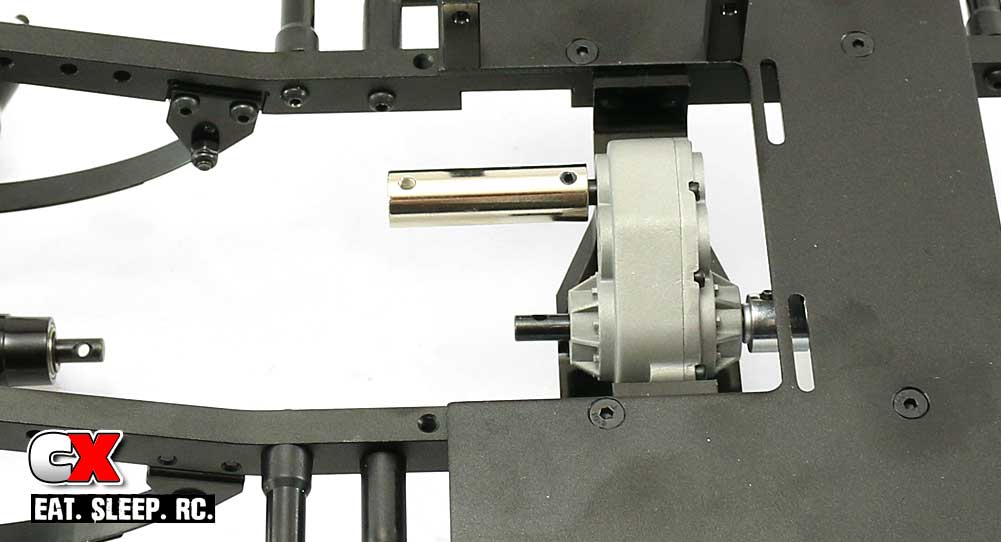
Attach the coupler to the transfer case, securing it with the M3 through-pin in place.
Step 2:
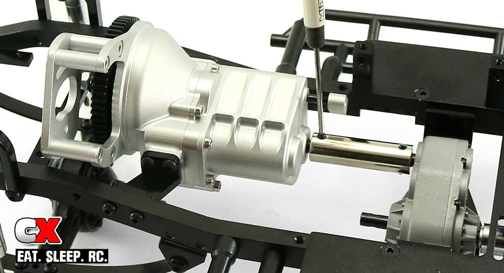
Align the output shaft on the gearbox (into the coupler) and slide into place – secure with another M3 through-pin. Attach the transmission to the frame rails with the 4 M3x10mm screws.
Step 3:
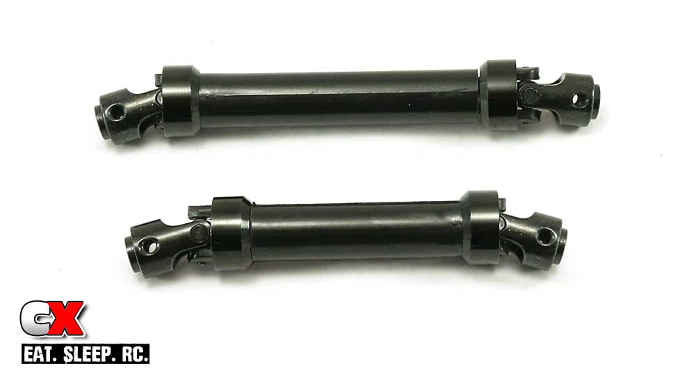
The driveshafts on the TF2 are heavy duty splined metal units. If they are not already mated, use the guide in the manual to properly slide them together. You’ll also notice they are two different lengths; the short driveshaft will go up front, the longer one to the rear.
Step 4:
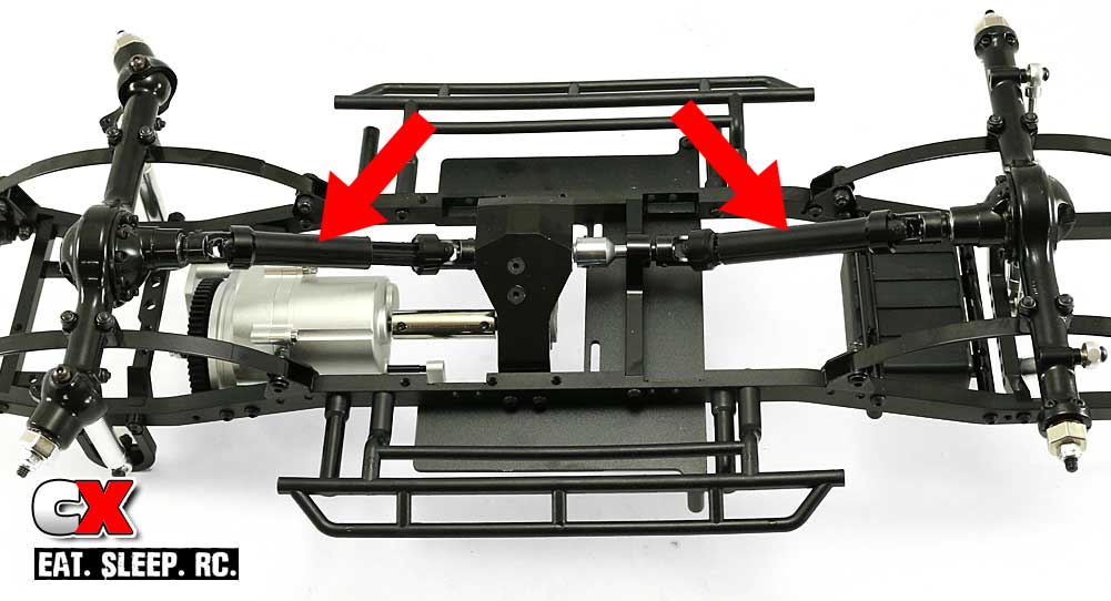
Feed the driveshafts onto the output shafts on the front axle and transfer case and secure with M3 through-pins.
Boom, quick and easy! Before moving on, turn the spur gear to make sure everything is rotating freely. If everything feels good, let’s move on to the steering and shifting.
RC4WD Trail Finder 2 LWB Build – Part 6
In Part 6 of our RC4WD Trail Finder 2 LWB Trail Truck build, we’ll be installing the steering, steering servo, shifting linkage and shift servo. Much easier than it sounds.
Build Notes:
• Before installing, it’s always best to hook up all the wiring and center the servos. This will ensure they are correct before attaching the linkage.
• Have some blue threadlocker available and use a small dab on any screws that thread into aluminum parts.
Step 1:
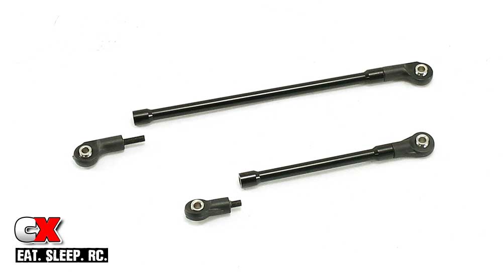
First, assemble the drag link and steering link. Note the orientation of the curved steering link rod ends.
Step 2:
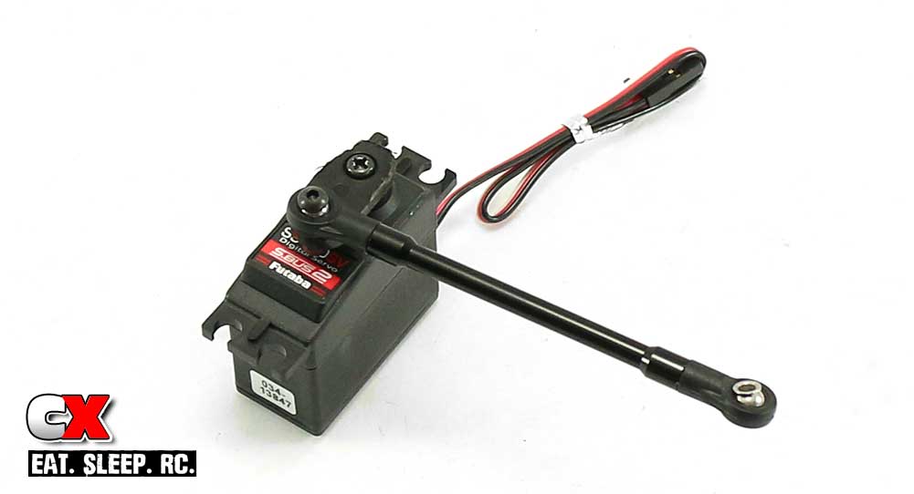
Attach the drag link to the servo horn (horn not included with the TF2) using a 3x14mm screw. This is not noted, but this is the length I found to be the best fit. Attach the servo horn to your servo. For this build, I’m using a Futaba S3470SV Steering Servo; lots of torque to help guide my rig through the toughest terrain!
Step 3:
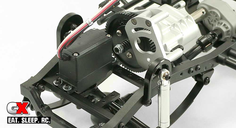
Install the servo into your TF2 with the servo output shaft towards the rear of the truck. Don’t worry about routing the servo wires yet; we’ll do that in a bit.
Step 4:
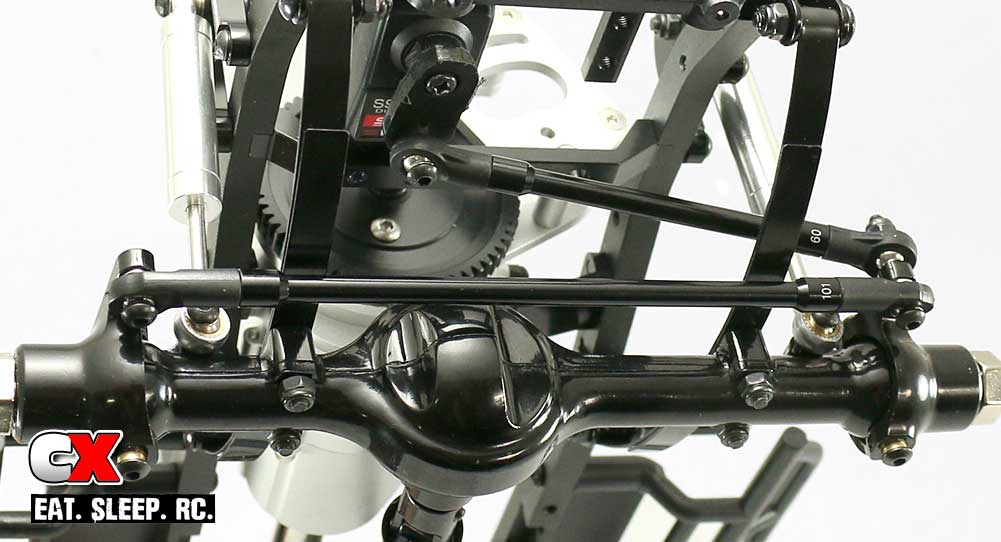
Connect the drag link and one end of the steering link to the left steering knuckle, then connect the other end of the steering link to the right steering knuckle.
Step 5:
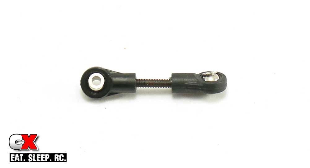
I changed the build up a bit here; it was easier for me to correctly install the drag link to the shift fork first. Start by building the shifting servo drag link. The suggested length of 35mm is spot on.
Step 6:
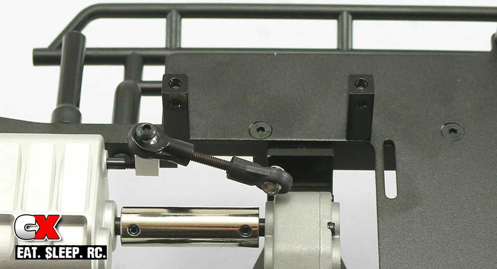
Attach the drag link to the shift fork lever.
Step 7:
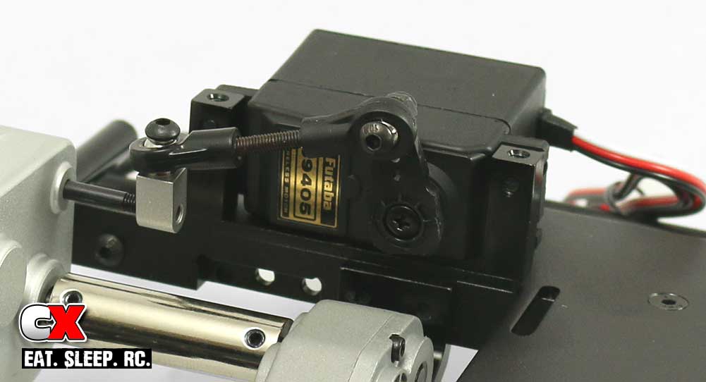
Install the servo to the mounts with the 4 M3x10mm screws. Attach the servo horn (included with your servo) on your servo with a slight offset as shown, then attach the drag link to the servo horn.
Since this servo is only going to be used to shift gears, a super duper high-end unit is not required. I opted to use Futaba’s S9405 servo; it has great torque and speed; 100oz/in and .11 seconds respectively. I still think it might be a bit overkill for this purpose.
Nice job – servos installed! Time to move on to the bumpers, wheels and tires.
RC4WD Trail Finder 2 LWB Build – Part 7
The RC4WD Trail Finder 2 LWB Trail Truck uses plastic, tube bumpers front and rear. For rollers, stamped steelies are wrapped in a set of great-looking scale tires.
Build Notes:
• The build process of the wheels is a bit challenging, but take your time and it’ll work. You really need to pinch them down to get them mounted; see Step 3 for an additional mounting notes.
Step 1:
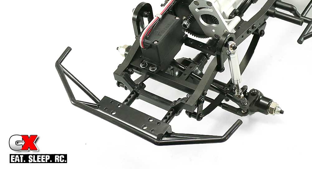
Install the front bumper into the mounts. Reference both the instructions and picture to get an idea of which mounting holes you should be using.
Step 2:
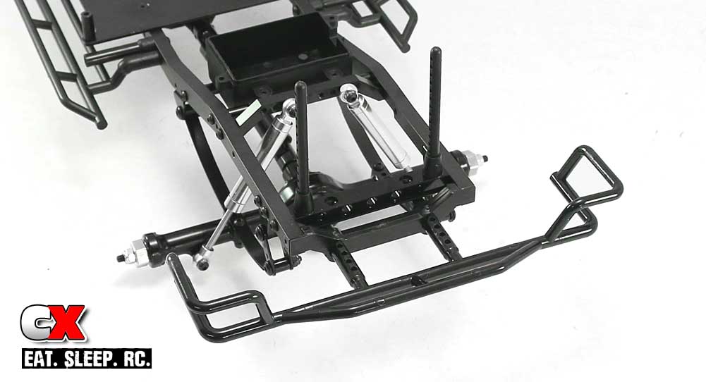
Use the same procedure here as you did in Step 1. If you feel either of these need adjustment, you can do that when you install the body.
Step 3:
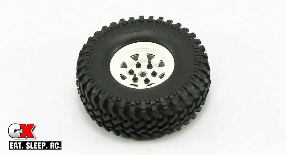
Ok, to install the stamped wheels, patience is definitely needed. The instructions state to use the longer M2x14mm screws to get the wheels initially pinched, then use the shorter screws in the remaining holes. This is key and, really, the only way you’re going to make this work.
Also, make sure you line up the see-through triangles in both the front and back parts of the wheel. If you don’t the wheels will have triangle ‘overlap’ and it will look funny. Test fit them and you’ll see what I’m talking about. Build all 4 wheel/tire assemblies.
Step 4:
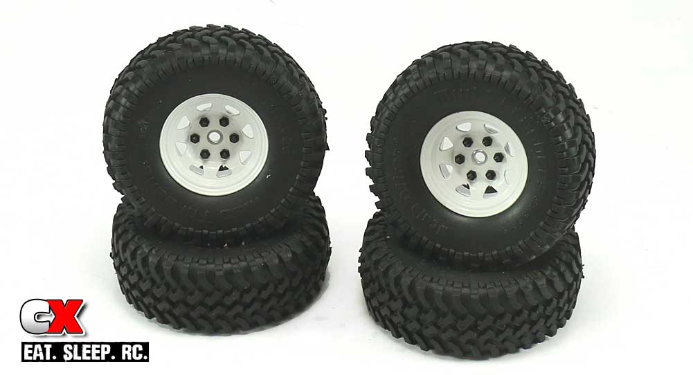
Here’s what your completed wheels/tires should look like. If you’re like me, you’ll want to take a short break after dealing with this. It’s definitely a tricky process but the final result is pretty rad.
Step 5:
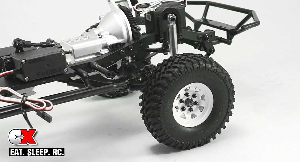
The cross pin, wheel hex and locknut were already attached to my axle, so all you’ll have to do here is remove the locknut, attach the wheel/tire combo and replace the locknut. Just make sure that the wheel pin doesn’t fall out during this procedure.
Woo hoo – look at that; we got ourselves a roller! Time to finalize this rig with some electronics and get it out in the dirt!
RC4WD Trail Finder 2 LWB Build – Part 8
Here we are – the final step! Part 8 of our RC4WD Trail Finder 2 LWB Trail Truck Build has us installing the electronics. We’ll be using a RC4WD Outcry Crawler ESC, RC4WD Brushed 45T Boost 540 Crawler Motor, ProTek RC 2S 4300mAh Shortly LiPo Battery and controlling it all with a Futaba 4PL Radio system. Let’s get to it.
Build Notes:
• I won’t be showing you my exact wiring, but you can see a general idea in the following pictures. Use small zip ties to keep everything clean and make sure to keep the wires away from any spinning parts.
Step 1:
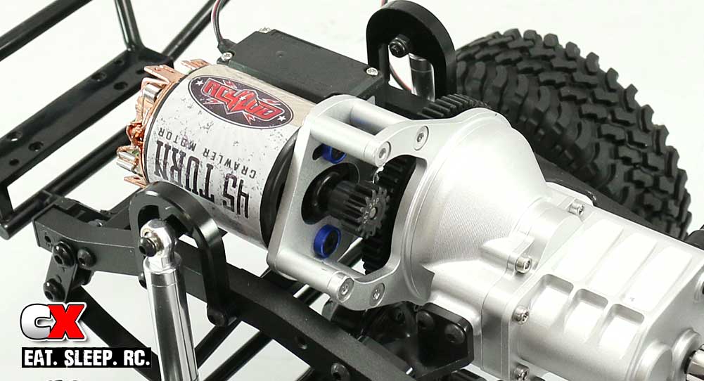
The first thing we need to do is install the motor and pinion. I used a pair of M3x8mm FH screws (and countersunk washers) to secure the motor in place.
I used a 14T 32P gear; your setup might vary.
Step 2:
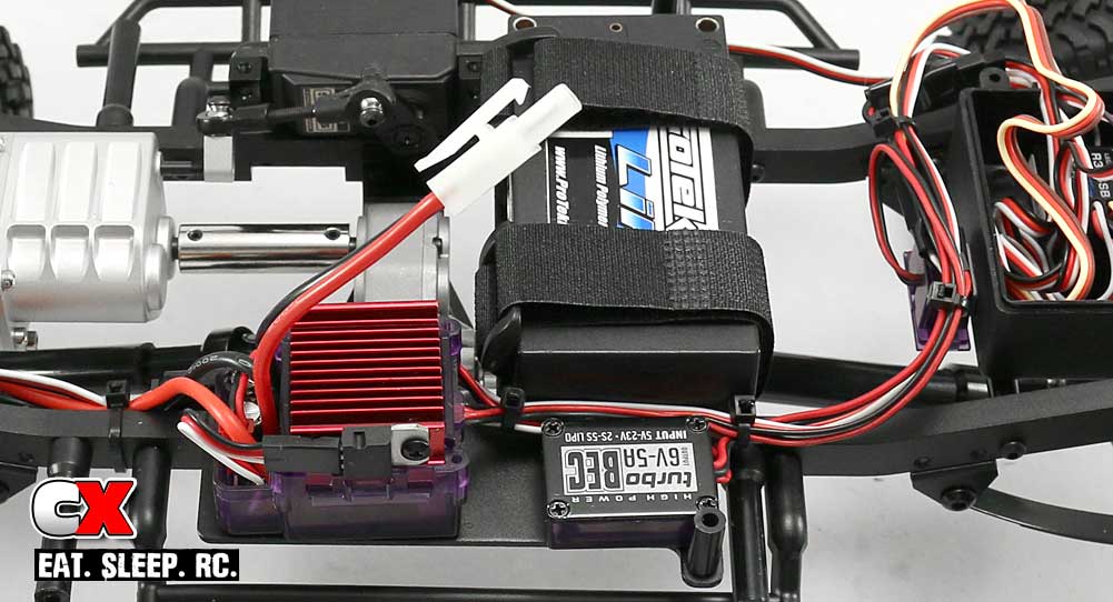
The ESC mounts opposite the shift servo, fitting nicely on the radio pad. The Outcry comes with an external BEC, so I mounted that right next to it. I’ll be replacing the white Tamiya plug with a Deans before I run this rig.
The ProTek shorty pack was used since the BEC took up a bit more space; if you’re not using an external BEC, a standard size will easily fit. Either way, the included Velcro straps kept the battery securely positioned.
Step 3:

I wrangled up all the wires and routed them to the opening in the receiver box. Everything fits nicely, however the box isn’t waterproof; something to keep in mind if you plan on fording any rivers.
Step 4:
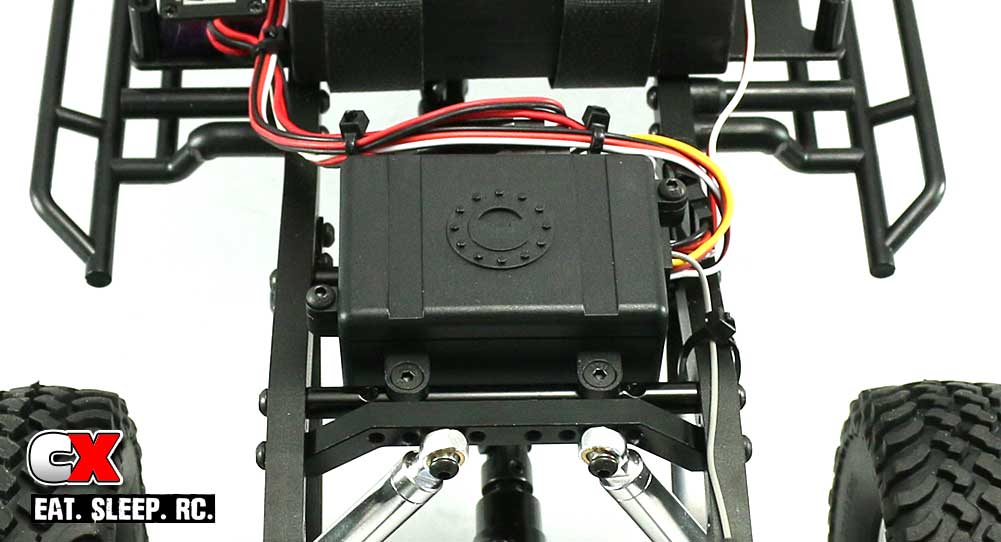
Once you get all your wires routed, attach the cover to the radio box. I used a pair of M3x8mm FH screws here as well to secure the lid.
Congratulations – your RC4WD Trail Finder 2 LWB Trail Truck is now ready for the trails! Well, almost. You still need to work paint and assemble the body. Good luck, and hope you enjoyed the build.

