Tamiya F104X1 Online Build
Formula 1 racing is starting to pick up here in Southern California. Maybe it’s the scale realism, the exciting handling or the competition. Or maybe it’s the inception of the seriously cool UF1 Series. Whatever the reason, this class has sparked my interest in onroad racing again and has me excited about each and every race. If you’re in the SoCal area, you should check out one of our races.
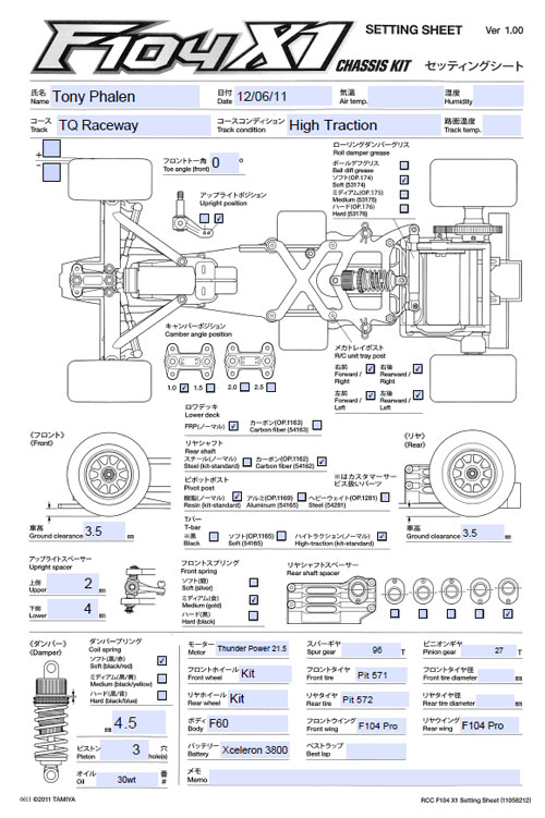
You can find the full, step-by-step build up right here on CompetitionX. I will be including a setup sheet and some build notes.
Tamiya F104X1 Online Build – Part 1
For the first steps, we will be building the rear suspension and pod.
Build Notes:
• The F104X1 is a pretty simple kit. A few standard tools is all that is needed, but do have a little it of blue loctite available for those metal-to-aluminum fasteners.
Step 1
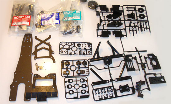
At the beginning of every build, I always recommend removing all the parts from the box to familiarize yourself with them. This will help you quickly and easily identify the parts for each step.
Step 2
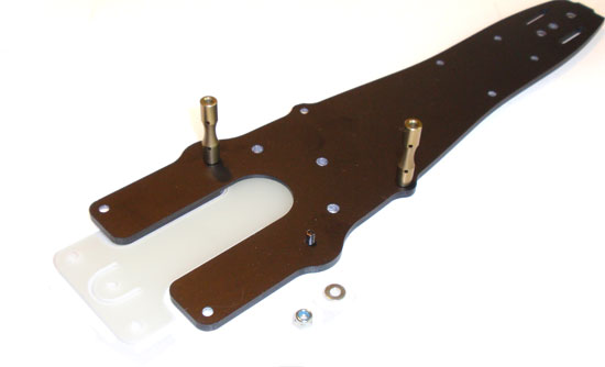
Attach the T-plate to the chassis. Make sure you pay attention to the countersink holes in the plate. Those face down. Also, since a few of the screws drive directly into aluminum parts, it’s a good idea to use a SMALL dab of blue loctite to hold them in place.
Step 3
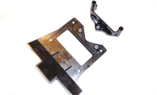
Insert the locknuts into the rear battery support and pod bottom plate/diffuser. They should be a snug fit. If not, a drop of grease will help keep them in place.
Step 4
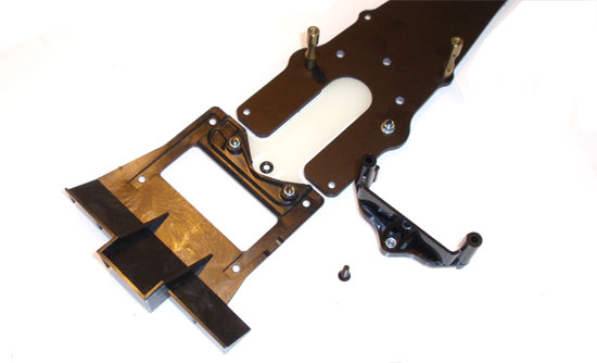
Attach the pod bottom plate/diffuser to the T-plate and the battery support to the chassis. Make sure you insert a black o-ring between the T-plate and battery support. Tighten this screw (the one that goes through the o-ring) until it is flush with the top of the locknut. We’ll adjust later.
Step 5
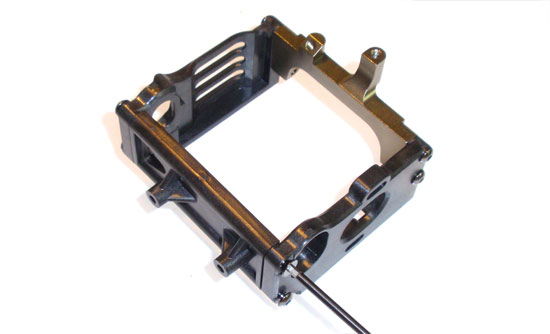
Assemble the rear pod, but don’t tighten down the screws yet. Apply a dab of loctite to the screws going into the aluminum.
Step 6
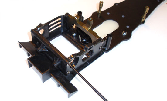
Attach the rear pod to the rear pod plate/diffuser. Tighten down these 4 screws. After you have done that, you can tighten all the screws from the step above. Torque until snug…you don’t want to warp the pod.
Step 7
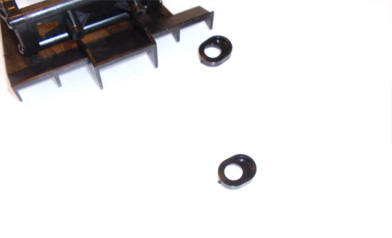
Remove the axle height spacers from the parts tree and remove any burrs (spare plastic). You can see a ‘nub’ in the picture. This is a burr that needs to be removed. Go ahead and choose the #2 spacer (it is printed on the part).
Step 8
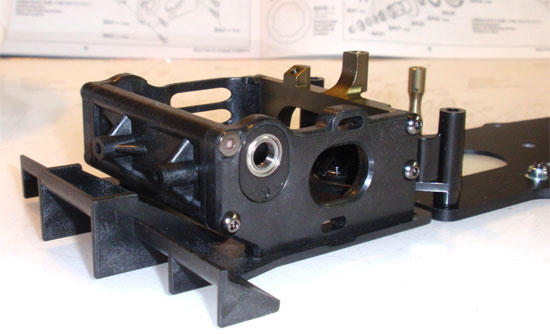
Insert an axle bearing into the axle spacer and press the assembly into the rear pod. Notice that the bearing is in the up position. This helps set the ride height on the F104X1 nice and low.
Tamiya F104X1 Online Build – Part 2
In step 2 we will be building the differential. This is the most important feature of your F104X1. A poorly built diff will result in a horrible handling car. Take your time here.
Build Notes:
• Grease is your friend when building the differential. Don’t be afraid to put a little extra on the balls and rings. Any excess will spin its way off.
Step 1
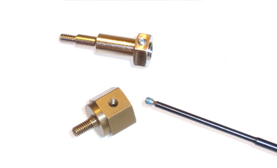
Prep the two wheel mounts by screwing the set screw in place. A little dab of blue loctite should be applied to both set screws.
Step 2
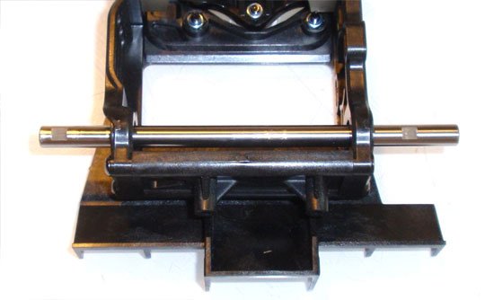
Slide the axle into place. Notice the orientation of the flat spots on the axle. It should be inserted as shown.
Step 3
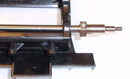
Slide the right side wheel adapter onto the axle. Align the setscrew with the flat spot on the axle and tighten down.
Step 4
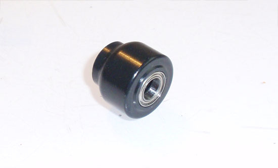
Insert a bearing on each end of the counterweight.
Step 5
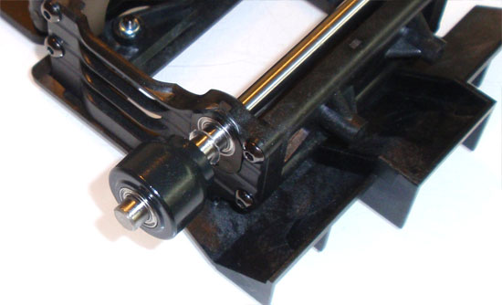
Slide the counterweight into place as shown. Don’t forget to add the small spacer inbetween the counterweight and the axle height spacer.
Step 6
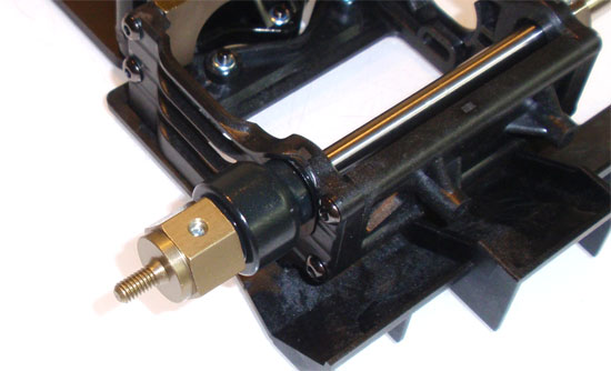
Slide the left side wheel adapter into place, align the setscrew with the flat spot on the axle and tighten. There is a small tolerance to where the setscrew tightens down on the flatspot. Use this to adjust the wheel adapters to allow about a 1mm side-to-side movement of the axle.
Step 7
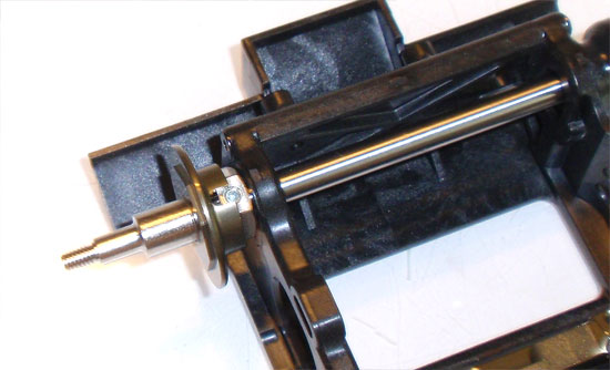
Attach the right side diff hub. Align the setscrew hole with the notch in the hub.
Step 8
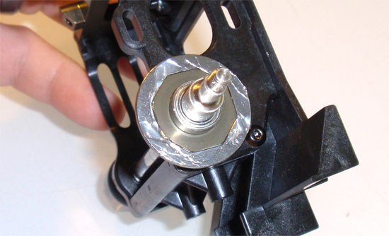
Drop the diff ring into place and key it to the hub. Apply a little silicone diff grease to the diff ring.
Step 9
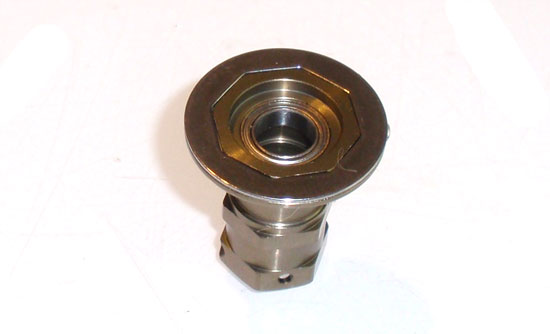
Slide the other diff ring onto the outer diff hub and key it into place. Then slide the bearing into the hub.
Step 10
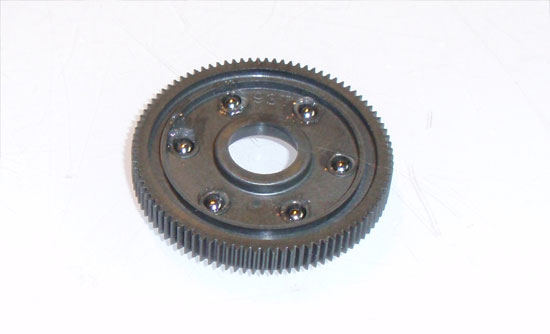
Apply diff grease into all the holes in the spur gear. Take one diff ball and place it into place on the spur gear.
Step 11
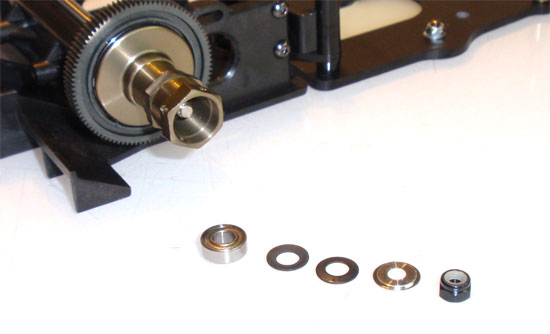
Insert a bearing into the spur gear and slide onto the axle. Take the outer diff hub and slide it on the axle behind the gear. Insert another bearing followed by the 2 cone washers and diff spacer. Notice the direction of the 2 cone washers. They need to be ‘facing’ each other. Finish the assembly with the locknut. Fully tighten the locknut and then back off a quarter turn. Hold both hubs (it’s easier if you slide the wheels on the hubs first) and try to turn the spur gear. It should not move at all. This is a good starting setup.
Step 12
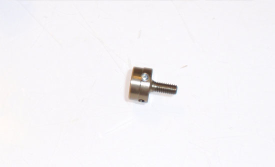
Insert the setscrew into the diff cap. Make sure you add a dab of blue loctite.
Step 13
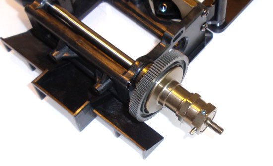
Insert the diff cap, lining up the setscrew with the ‘middle hole’ on the outer diff housing. The middle hole is defined as the one on the ‘corner’ part of the outer diff hub. Once in place, slide the axle pin through the other hole and center. Lock the pin into place with the setscrew.
Tamiya F104X1 Online Build – Part 3
Part 3 is simply installing the motor. It’s an easy section and only requires 3 steps.
Build Notes:
• Pay attention to the direction of the motor spacer. The cooling fins should be facing the motor.
• Only 540 motors will fit the F104X1 (either brushed or brushless).
Step 1
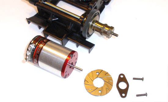
Installing the motor is pretty simple. Slide the screws through the motor plate, rear pod, motor spacer and into the motor. Do not tighten yet. The motor plate and motor spacer are required to help cool the motor since the rear pod is made out of plastic. If you upgrade the rear pod to aluminum, both of these pieces can be eliminated. Also, make sure the wire connecting tabs on the motor (and sensor wire harness) are all pointed up to make it easier to solder.
Step 2
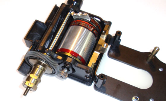
Once the motor is in, you can attach the pinion gear.
Step 3
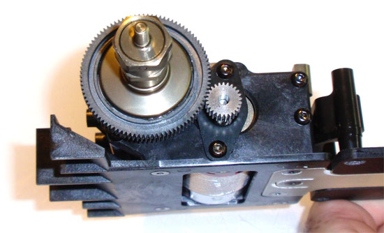
Slowly slide the motor towards the spur gear until the pinion and spur make contact. Back the motor of a tick and tighten the motor screws. You want there to be a TINY HINT of backlash (free play) between the pinion and spur…as little as possible since we are running 64p gears. If there is too much space you’ll strip the spur, so a smaller gap is better here.
Tamiya F104X1 Online Build – Part 4
In step 4 we will be installing the lower front suspension. The upper front suspension will be a later step as it incorporates the steering parts as well.
Build Notes:
• We will be building the F104X1 with 1 degree of front camber. With the tire setup we are running in our UF1 Series, more camber might be seriously overkill.
• Make sure you build the front turnbuckles with the turnbuckle-shaft notch facing the same way. This makes it easier to adjust them in the same direction.
Step 1
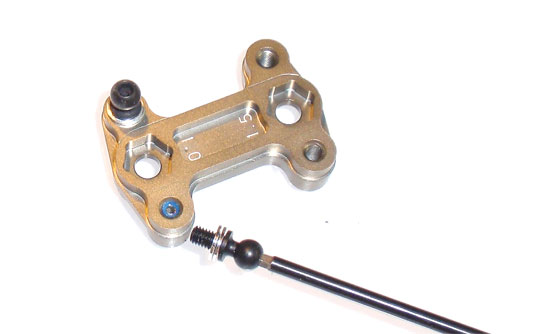
The first step is to install the ballstuds into the Camber plate. Start by sliding two shims on each ballstud. Apply a dab of blue loctite into the 1 degree holes in the Camber plate and install the ballstud.
Step 2
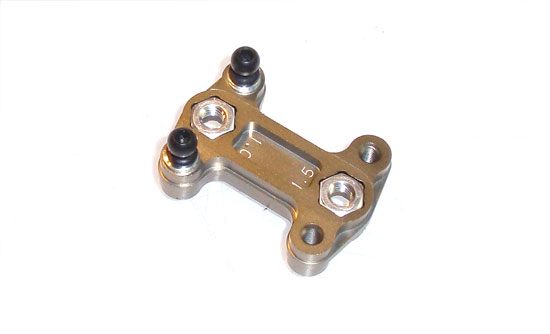
Next, slide the two nuts into the retaining holes on the Camber plate.
Step 3
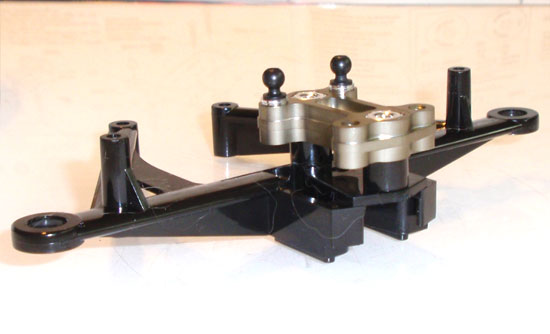
Fit the two spacers to the lower front suspension arm followed by the Camber plate. Notice that the ballstuds are towards the back of the assembly.
Step 4
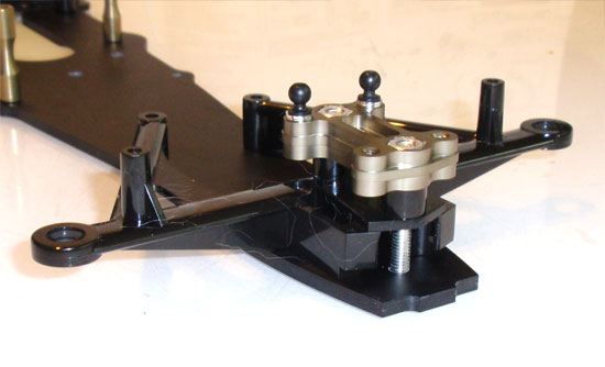
Install that assembly to the front of the chassis plate and fasten with the two 4x30mm screws. These are aluminum screws so be careful not to overtighten and strip out the head.
Step 5
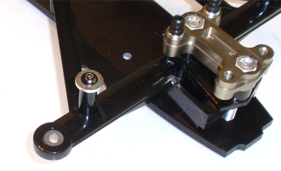
Attach the 3x10mm screw and washer to both lower front suspension arms. These are the steering stops and are required. Leaving these off can over-extend the steering and lock it to one side. Also pop the aluminum balls into the lower front suspension arms. Pay attention to the direction of the balls. The ‘flange’ should be facing down.
Step 6
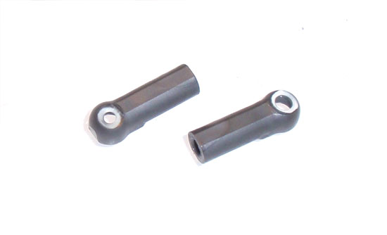
This is not a necessary step but one I highly recommend. When you install ballcups, the first time you pop them on they are a nice, tight fit. Repeated removing and replacing tends to widen the cup and produce some slop. To help prevent this, I shave the top of the ballcups off. Now, when I need to make adjustments or replace something, instead of popping the ballcup off I stick a tool through the hole and unscrew the ballend.
Step 7
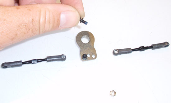
The next step is to install the ballends through the aluminum servo saver. A dab of blue loctite here is helpful. Build the turnbuckles per the instructions. The manual says 22mm in length but I think mine was a little shorter.
Step 8
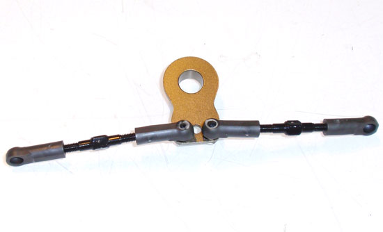
Pop the turnbuckle links on and you’re all set!
Tamiya F104X1 Online Build – Part 5
The servo assembly is a bit tricky and requires some additional love. I thought I’d make this it’s own step.
Build Notes:
• You will be highly modifing the case on your servo. If you don’t want to do this, use a inexpensive servo.
• There are other servo savers out there you can use, like one from Kimbrough Racing Products. These are excellent replacements if you are interested in swapping out the stock one.
Step 1
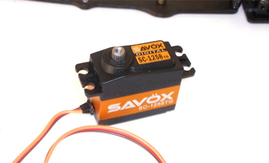
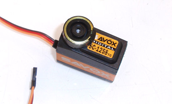
For steering duties I’ll be strapping in Savox’s SC1258TG servo. This bad johnny boasts a stellar .08 60 degree transit speed with over 165 oz of torque. Maybe a bit overkill, but this is a Formula 1 car.
Step 2
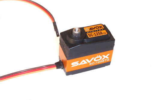
Unfortunately, you will need to maim your high-end servo to fit into the F104X1. Start by sheering off the mounting ears on both sides of the servo. You can then use a dremel (or similar) and grind the plastic flat. Both sided will need to be as flat as possible.
Step 3
Install the correct servo horn (this will depend on your servo) and the three servo saver springs. These can be a little difficult to get on so be patient.
Step 4
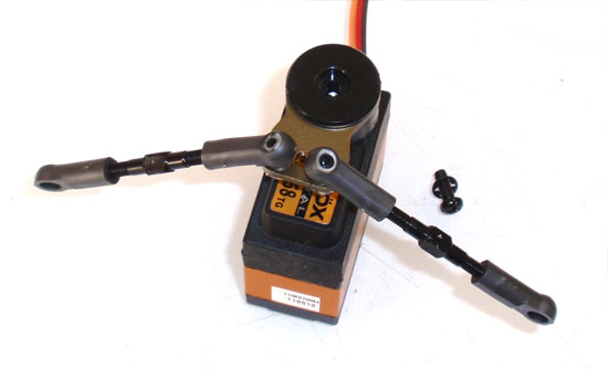
Once the horn and springs are installed, slide the assembled aluminum servo horn into place, attach the servo saver cap and add the screw.
Step 5
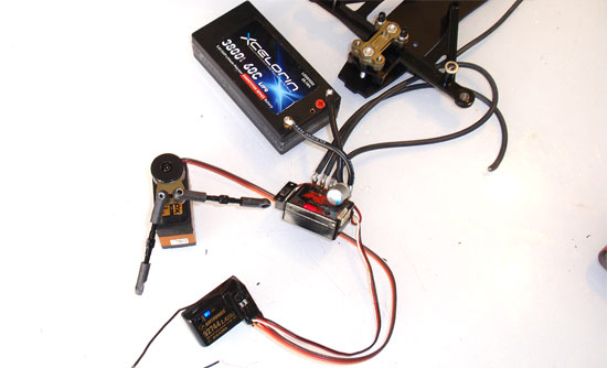
At this time, you will want to get all of your electronics together to verify everything is working properly. It would suck to install it all and find out something isn’t working. This will also give you a chance to make sure your servo is properly centered (actually, the main reason we are doing this now).
Step 6
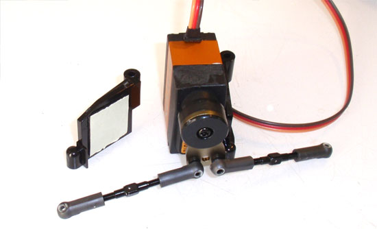
Once you’ve verified your servo is properly centered, attach the servo mounts with a small square of double-sided tape. To this on a flat surface so you can mske sure the servo and mounts all line up properly at the bottom.
Step 7
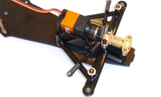
Place the servo assembly onto the chassis and attach with the two forward screws. Make sure the backmost holes in the servo mounts line up with the holes in the chassis. You can test fit with the long 3x35mm screws.
Tamiya F104X1 Online Build – Part 6
The top deck is a simple, straightforward step.
Build Notes:
• The electronics mounts can be used in their stock configuration or modified to work as a battery stay. If you are using any kind of shorty LiPo pack, these can be used to hold the battery in place, eliminating the need for battery tape.
Step 1
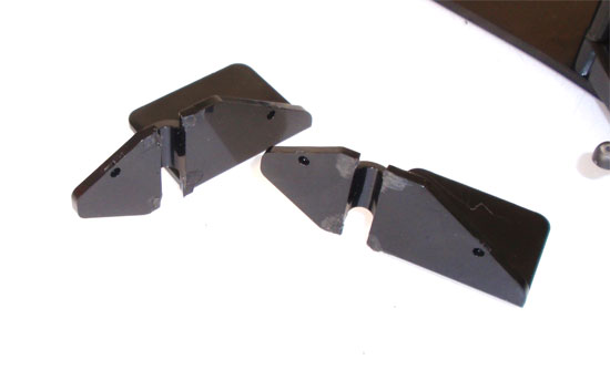
The manual has you installing the electronics mounts over the posts. Building it that way is completely fine, but a buddy of mine showed me a trick way to utilize these. With a dremel, shave off the hoops on the side shown. Don’t cut down into the channel, just smooth the side off. Put these aside for now and we’ll get back to them.
Step 2
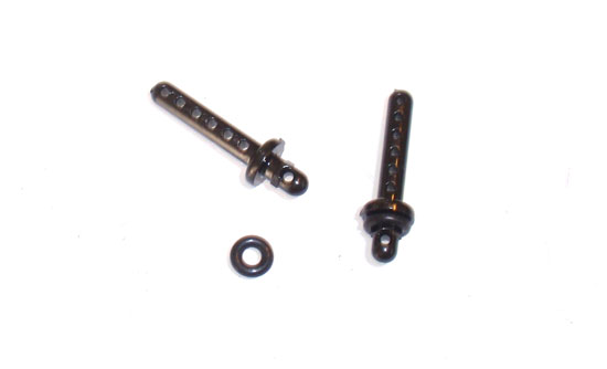
Slide the black o-rings over the rear body posts.
Step 3

Install the body posts and antenna mount to the upper deck. The o-rings on the body posts help give them a little bit of float, helping to save the body in a crash as compared to a rigid body mounting system.
Step 4
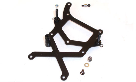
Attach the center shock and side damper ballends. Place a little blue loctite on the center shock mount screw…don’t forget the shim! The side damper ballend does not need loctite because it already screws into a locknut.
Step 5
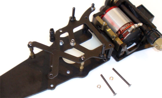
Attach the top deck to the chassis. If you are using the electronics mounts as the come in the kit, you will need the black o-rings. If you are going with the optional method, you can leave those off. Don’t forget to add a small dab of blue loctite on all the screws.
Tamiya F104X1 Online Build – Part 7
Today’s electronics are super-small and very light. While their placement is not super critical on the performance of the car, we do want them as close to the centerline as possible.
Build Notes:
• The F104X1 is considered a pan-car style chassis. Because of this, using thick wire from the ESC to the motor can hinder the movement of the rear pod. I would suggest using nothing bigger than 16g wire. It’s flexible enough and will still transfer plenty of power to the motor.
• There isn’t a ton of room under the F1 body. Tidy wires are essential for a nice, clean fit.
Step 1
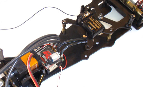
Wire up and install the ESC right behind the servo. Hopefully you will be using an ESC with a small footprint. Tape the receiver on the top deck, right in front of the center shock mount.
Step 2
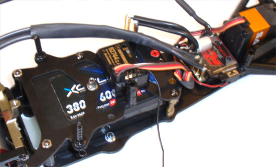
Install the battery. Since I am using a shorty LiPo pack, it allows me to move the pack forward or back to help with weight transfer and handling. I run the pack approximately 7mm forward of the top deck. Make sure you make your ESC wires long enough to reach this spot or farther back if you move the battery back.
Step 3
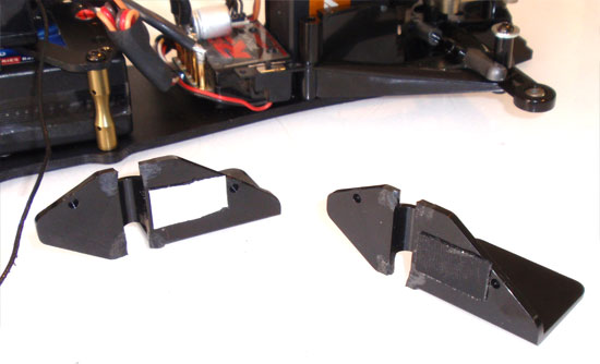
Now the cool trick. Take your electronics mounts and add a small piece of double-sided tape to them, as shown.
Step 4
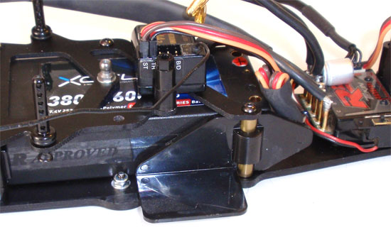
Take these mounts and snap them into place onto the top deck standoffs. Since you (hopefully) didn’t grind down into the channel, they will still pop into place. The double-sided tape holds the battery securely in place. To move (or remove) the battery, simply pop the electronics mounts off and slide the battery around. I’ve been running my F104X1 like this for some time and not had any issues with the battery moving or the mounts coming off.
Tamiya F104X1 Online Build – Part 8
This part will complete the front suspension build. Tamiya has included 3 sets of springs to help you tune your F104X1 to different track conditions. You can also adjust ride height but putting the shims above or below the steering upright.
Build Notes:
• After building the front end, it is suggested that you apply a thick-ish oil to the front suspension to help smooth it out. I use 3000wt Team Associated Gear Diff Lube. That seems to work really well and it’s thick enough to stay in place.
Step 1
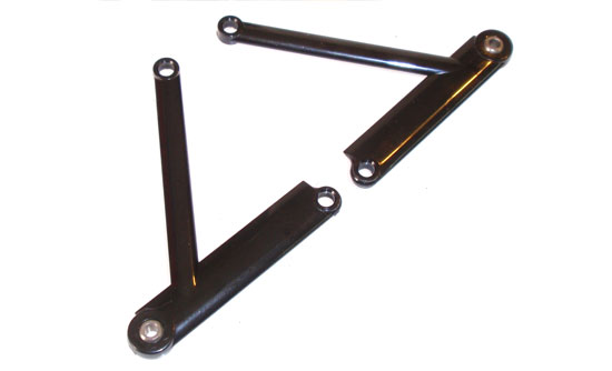
Insert the aluminum balls into the upper suspension arms. Do this for both sides. They are non-directional so that doesn’t matter.
Step 2
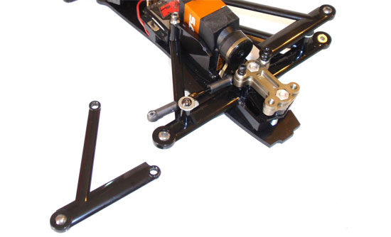
Insert the 3x35mm screws through the chassis and into the ball connector nut. If you are using the optional electronics mount system, you don’t need the front upper deck. If you do remove that, it’s optional to place spacers in it’s place. Pop the upper suspension arms onto the ball connector nut.
Step 3
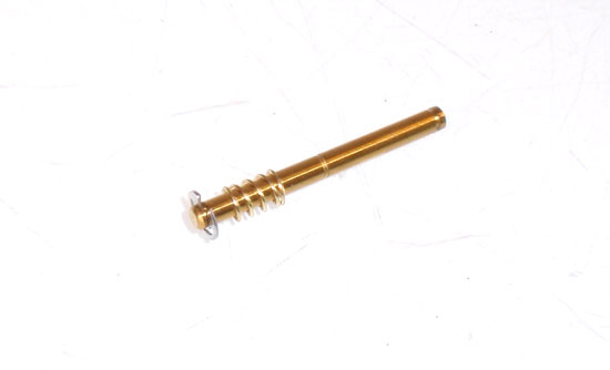
Snap an e-clip onto the kingpin and install a front spring. The F104X1 comes with 3 different sets of front springs. I use the stiffest, the golds, simply because we are using a super soft front tire and the gold spring helps control front dive. Build 2 of these.
Step 4
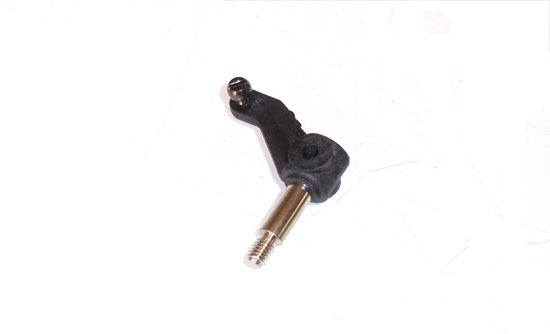
The steering upright comes pre-assembled with the F104X1. You will need to install the ballend, though. Use the stock location. Do this for both sides.
Step 5
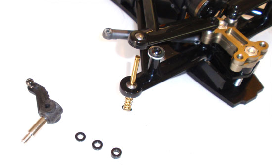
Slide the kingpin up through the lower suspension arm, through the spacers and the steering upright. Spacers can be loaded per the manual; thick below the steering upright and the two thing above it. Do this for both sides.
Step 6
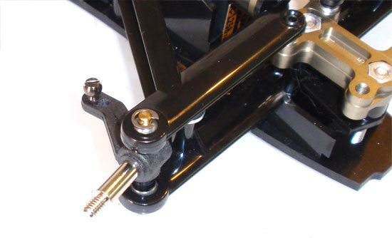
Capture the assembly with an e-clip on top. Install the setscrew into the back of the axle. A dab of blue loctite will help keep it in place. Do this for both sides.
Step 7
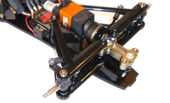
Pop the steering ballcup into place. Do this for both sides.
Tamiya F104X1 Online Build – Part 9
The shock and roll damper are the 2 major handling components of the F104X1. Take your time building these as they can drastically affect your car’s performance.
=
Build Notes:
• To make the build process easier, prep all the plastic parts before starting to build your shock. Trying to find a place for an oil-filled shock with no lid can sometimes prove quite difficult.
• Shock building can be messy. Have some paper towels available for clean up.
Step 1
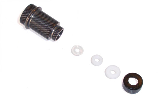
Tamiya has included one of their awesome TRF threaded shocks with the F104X1. Yay. To start, insert the clear o-ring, spacer and rod guide into the bottom of the shock body. Cap this off with the aluminum shock bottom.
Step 2
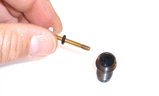
Install the two e-clips and 3-hole piston onto the shock shaft. Apply a little shock oil to the threads on the shaft and slide the black o-ring onto it. Insert the shaft into the shock body and feed it through the bottom. At this time you can also attach the shock rod bottom.
Step 3
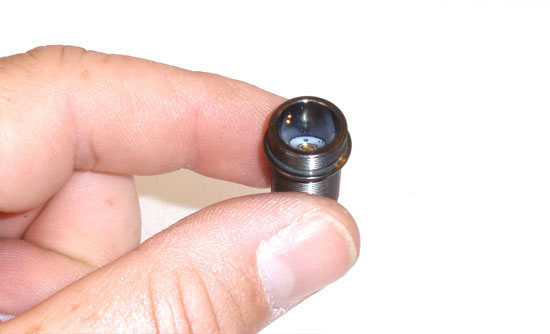
Fill the shock to the top with silicone oil (I used Team Associated’s 30wt). SLOWLY slide the shaft up and down a few times to remove any air bubbles below the shaft. When the shaft is in the down position, the oil level should be alot lower now. Fill back up to just below the top. SLOWLY slide the shock shaft up and down again to make sure all the bubbles are gone.
Step 4
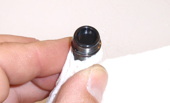
Wrap a paper towel around the shock and place the rubber bladder on top of the shock. It’s best if you slightly fold the bladder over and ‘roll’ it onto the top of the shock. This will force any excess oil out one side of the shock instead of randomly all around. Make sure the bladder is completely seated on the top of the shock body. The paper towel helps keep things clean.
Step 5
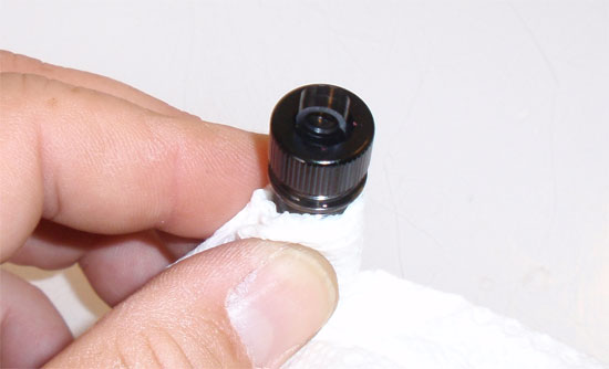
Place the shock cap mount on top of the bladder. Slide the aluminum cylinder cap over the shock cap mount and screw into place. A nice, snug fit is all that is necessary.
Step 6
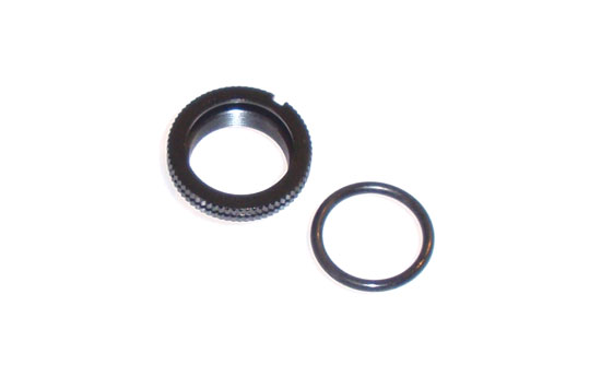
Fit the o-ring into the groove in the threaded spring retainer. Apply a little bit of shock oil to your finger and line the installed o-ring. This will make it thread on the body much easier.
Step 7
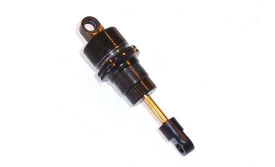
Thread your spring retainer assembly onto the threaded shock body. Start with about a 4-5mm gap between the spring retainer and the shock lip.
Step 8
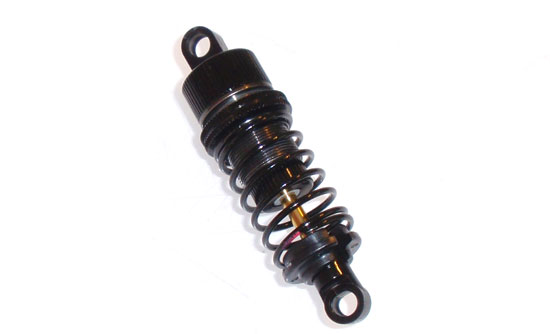
Attach the center spring followed by lower spring retainer. Key the retainer to the shock end.
Step 9
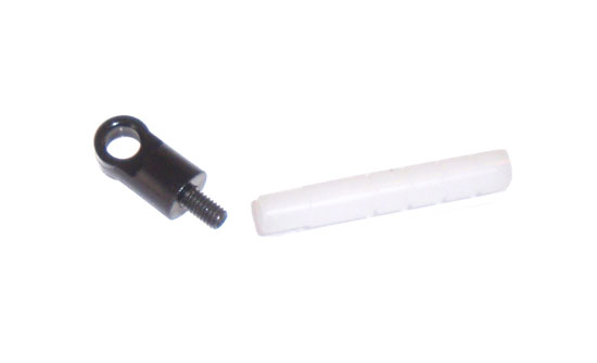
Install the 3x10mm setscrew into the shock rod end. Screw the opposite end into the roll damper piston.
Step 10
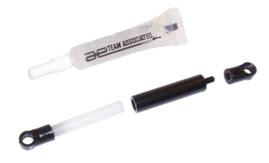
Feed the shock rod end onto the roll damper cylinder. Apply some grease (I use Team Associated’s white diff grease) to the roll damper piston and slide up into the the roll damper cylinder. It’s best to apply a bit of grease and use your finger to smooth it down into the notches. Attach both the shock and roll damper to your chassis.
Tamiya F104X1 Online Build – Part 10
Tires make a huge difference in the handling of the F104X1. Check your local track to find out what tires they are running before you glue them on.
Build Notes:
• Take your time when gluing the tires into place. Nothing is worse than a tire coming off the wheel during a race. Try using my CompetitionX Gloo Toobs for a nice, strong bond.
• The front aluminum screws are pretty soft. A hard hit to the front end can cause those screws to bend and cause serious handling issues. Check these out from Exotek Racing Exotek F1 4x30mm Titanium Screws
Step 1
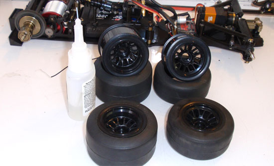
There are quite a few manufacturers of tires for the Tamiya F1s, but I’ll be going with Pit Shimizus. These seem to work the best on most surfaces and don’t wear very much. To keep the mess to a minimum, I use my CompetitionX Gloo Toobs. Feel free to head over and purchase a package. The proceeds help support this site.
Step 2
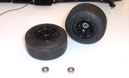
Insert the bearings into the front wheels; one on each side.
Step 3
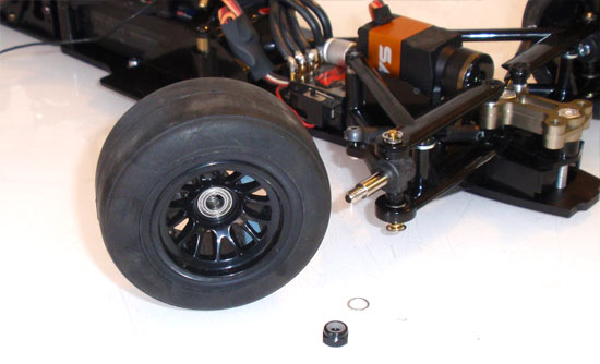
Slide the spacer onto the front axle followed by the front wheel. Hold everything in place with a standard locknut. Do this on both sides.
Step 4
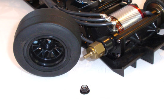
Slide the rear wheels onto the hubs and hold in place with the flanged locknut.
Step 5
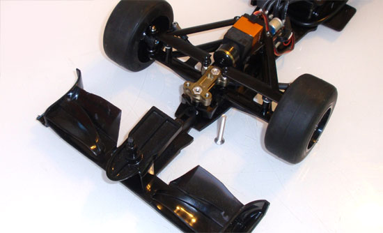
Assemble the front wing per the instructions. Remove the front-most aluminum screw that holds the front suspension to the chassis and slide the front wing into place. Replace the aluminum screw.
Step 6
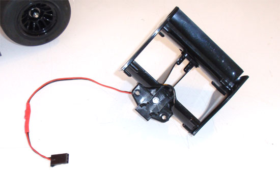
Assemble the rear wing and attach to the rear of the chassis. As an added realistic touch, I added a blinky ‘rain’ light that plugs straight into the receiver. It draws next to nothing in amperage and gives the F104X1 a killer look.
Tamiya F104X1 Online Build – Part 11
The body is the first thing people will see on your F1104X1. Make it beautiful!
Build Notes:
• None.
Step 1
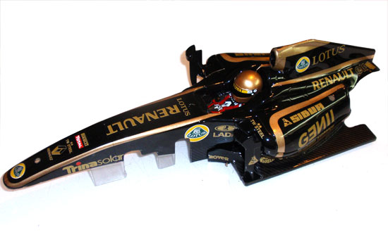
The final step is the body. Paint it and sticker it however you like. Don’t forget to assemble and attach the helmet. I had Brad over at F1 RC Lab do it up for me. His work is exceptional and I just wish every one of you could see it in person…the pictures don’t do it justice! If you want an F1 done right, check out Brad’s site. He’s got quite the assortment of F1 liveries to choose from.
Step 2
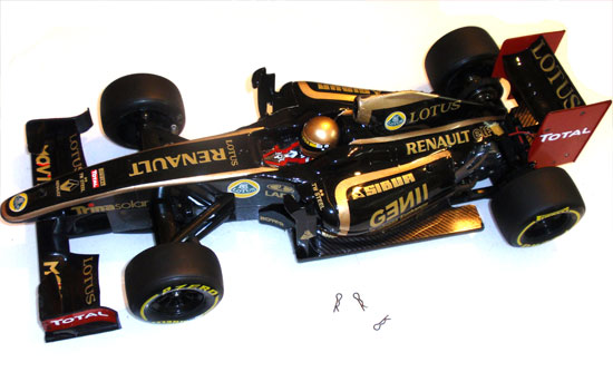
The holes should already be pre-drilled (depending on your body). Carefully mount the body and attach the body clips.
Step 3
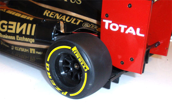
While not necessary, it’s a cool idea to spice up the build with a set of realistic wheel decals. You can contact Mark Goldwater to pic up a set of these killer decals here: mgoldwater@verizon.net
And that’s it; the full build from parts bag to full race setup. Thanks for following along with this build and let your friends know it’s here.
If anyone is interested, you can download the carpet setup below: