

Tamiya TA07 Pro Online Build
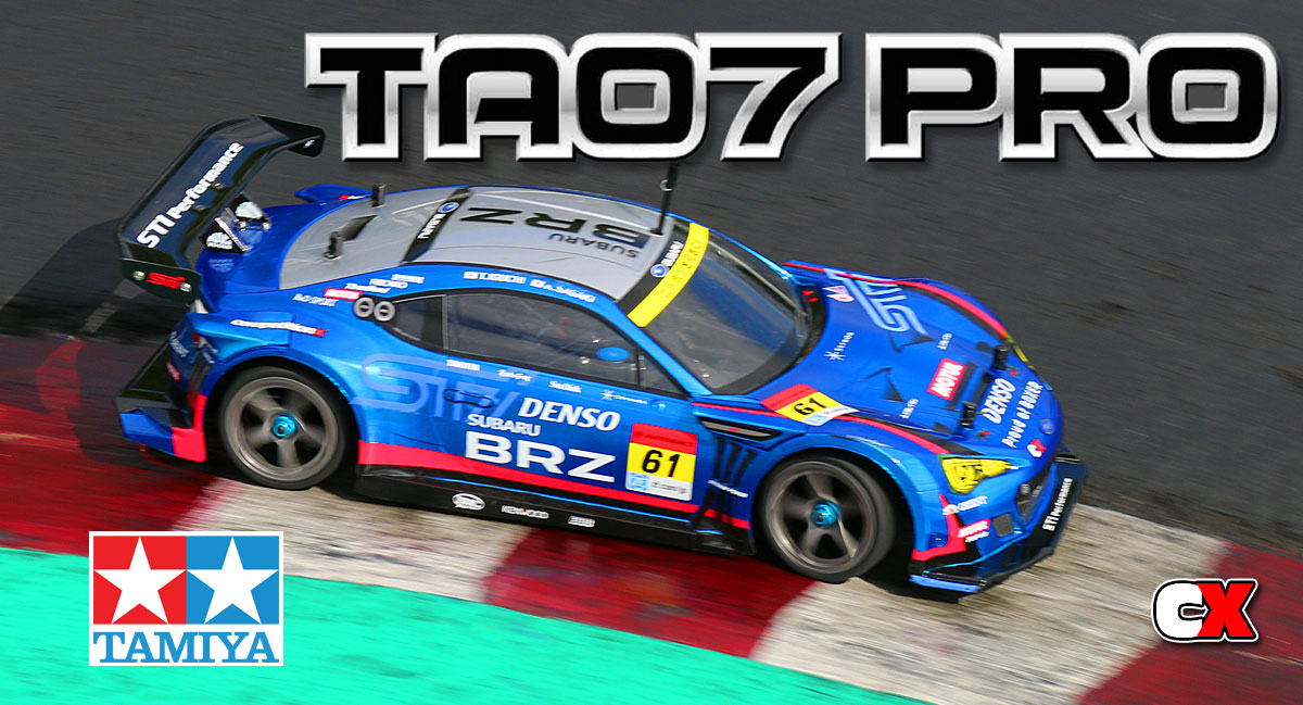
Tamiya’s TA07 Pro is the newest in a long line of budget onroaders geared to those wanting the thrill of onroad racing without having to shell out the big bux for a high-end TC. However, this car has seen some serious potential on the track, with more and more drivers gravitating from their current Tamiya rides over to this new platform.
Follow along as we complete the project, installing support gear from Futaba and HobbyStar.
Tamiya TA07 Pro Online Build – Part 1
Tamiya has us starting the build of the TA07 Pro with the rear suspension. It pulls parts from the TRF419, so you know right off the bat you’re getting a car that can be tuned for maximum performance.
Build Notes:
• In Step 4 you will be assembling the lower belt pulley. There are two similar spacers that are available to slide between the bearings; make sure you are using the 3x5x.03mm one – it’s the skinnier of the two.
Step 1:
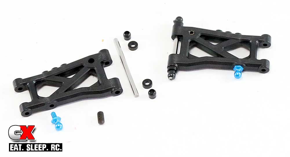
The first thing we need to do is assemble the rear suspension arms. Start by screwing in the droop screws as shown, making sure that they are sticking about 1mm out of the bottom of the arm. Next, attach the blue ball ends into the arms. Finally, slide the hinge pin through the arm, adding a washer and suspension ball to each end. I suggest using a small amount of black grease to keep the hinge pin parts intact while assembling.
Step 2:
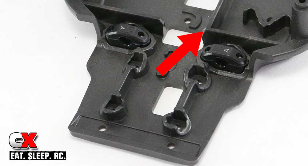
Attach the rear C arm mounts to the chassis. We’ll be using the ‘A’ block here, so make sure the ‘A’ label is to the outside. I’ve highlighted it for reference. At this time, you’ll also want to cut off the plastic chassis overflow piece. I suggest cutting it off at a slight angle as shown. This will help out later in the build.
Step 3:
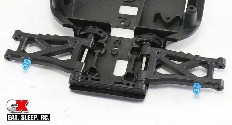
Slide the arms in place (note the orientation) and slip the rear 1D arm mount onto the chassis, securing it from underneath with the two 3x8mm screws. Make sure the arms move up and down freely.
Step 4:
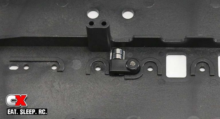
Assemble the lower belt pulley. Make sure you don’t over-tighten the compression screw. Attach the assembly to the chassis as shown.
Step 5:
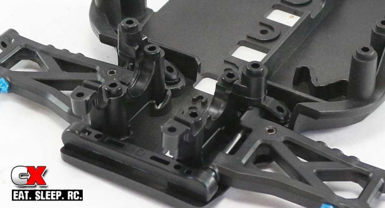
Attach the bulkheads to the chassis. Note the orientation. Do not tighten them down all the way just yet; we’ll do that at a later step.
Part 1 of the rear suspension complete. Time to move on to the front suspension.
Tamiya TA07 Pro Online Build – Part 2
The front suspension build is up next, also pulled from the TRF419. The assembly is very similar to the rear suspension and we’ll be including the steering posts here as well.
Build Notes:
• None.
Step 1:
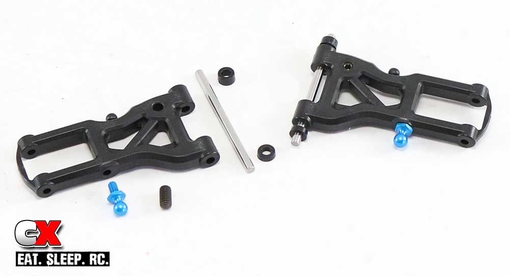
We’ll be assembling the front suspension arms like we did the rears; screw in the droop screw (with 1.5mm sticking out of the bottom) and attach the blue ball ends. Slide the hing pin through and attach the spacers; there are no suspension balls on the front arms.
Step 2:
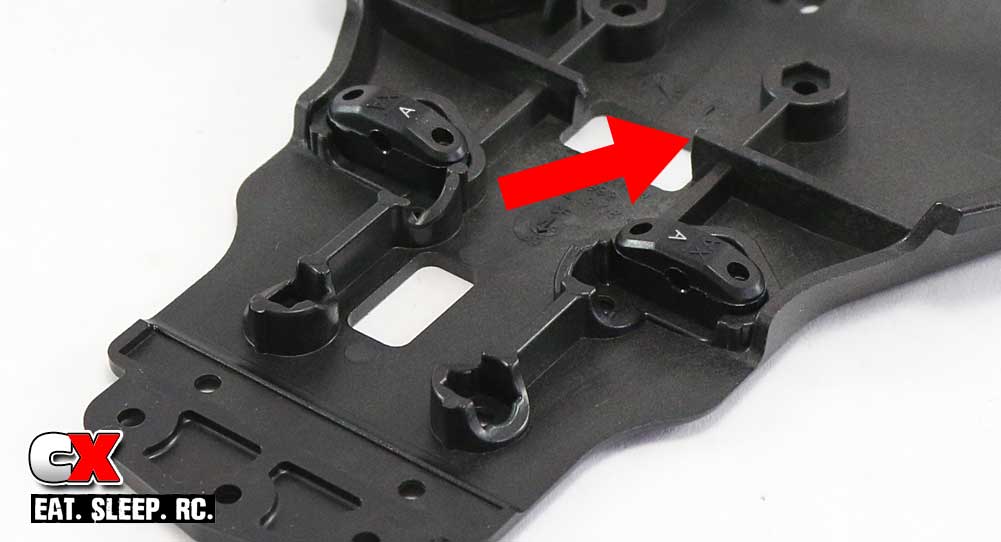
Attach the front B arm mounts to the chassis with the ‘A’ facing in. I’ve highlighted the ‘A’ for reference. Like the rear, cut off the plastic chassis overflow piece, shearing it off at a slight angle as shown.
Step 3:
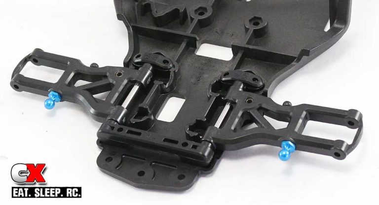
Slide the front suspension arms into place (note orientation) and slip the front 1A arm mount onto the chassis, securing it from the bottom with the pair of 3x8mm screws. Make sure the arms move up and down freely.
Step 4:
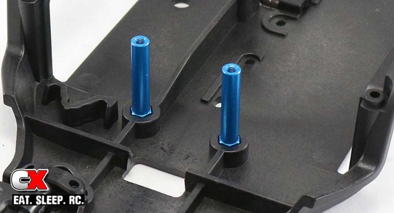
Attach the blue steering posts to the chassis. A light dab of blue threadlocker is suggested here.
Step 5:
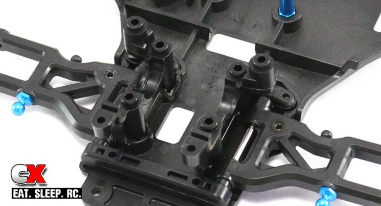
Attach the bulkheads to the chassis. Note the orientation. Do not tighten them down all the way just yet; we’ll do that at a later step.
Part 1 of the front suspension complete. Next up is the motor mount and spur gear assembly.
Tamiya TA07 Pro Online Build – Part 3
The motor mount assembly on the Tamiya TA07 Pro is quite unique. It has three different possible mounting positions, allowing for three very different handling options. To accommodate this, a single, serpentine belts is used, wrapping its way around a series of pulleys.
Build Notes:
• As with almost every car, Tamiya uses a .06 Mod gear pitch for the spur and pinion. This is great if you have a bunch of Tamiya pinions (or spur gears) lying around to adjust the ratio, but if you don’t (like me), then you need to switch to something else. For the build I’ll be using the Tamiya gears, but shortly after Part 3 of the build I swapped them over to 64P – I have a TON of these gears so making gear changes will be much easier for me.
• The pulley tensioner and belt tensioner can be adjusted to tighten up or loosen the belt tension. Start with the manual-suggested locations. If you want a bit more speed, loosen both tensioners so the belt has more slack.
Step 1:
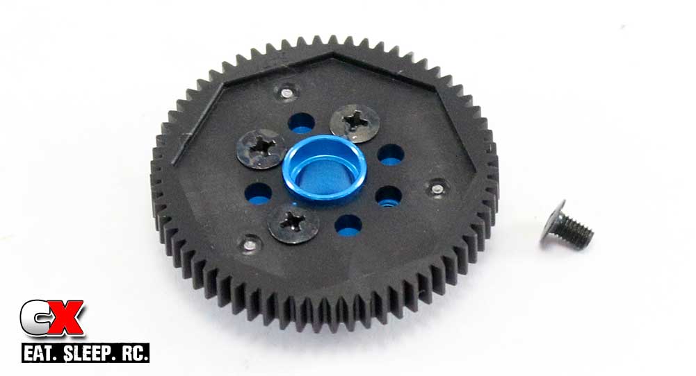
Start off by attaching the spur gear to the aluminum hub. It only attaches in one direction so you can’t build this incorrectly.
Step 2:
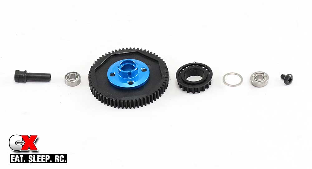
Assemble the spur gear shaft and pulley. Note the ‘slots’ in the blue spur gear adapter; they key with ‘ribs’ on this inside of the pulley gear. Also note the flanged bearing location. I would suggest a very small dab of blue threadlocker on the retaining screw as well.
Step 3:
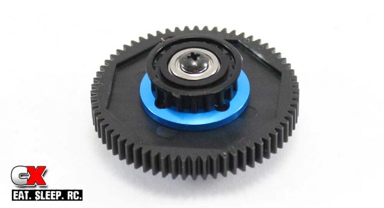
Here is the assembly when complete.
Step 4:
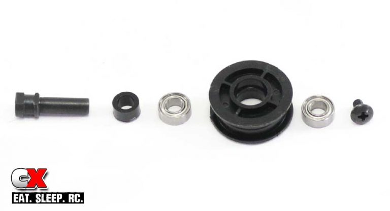
Assemble the pulley tensioner. The first step is to glue the two pulley halves together; use CA glue but be careful not to use to much. You don’t want the glue to ‘ooze’ onto the flat spot of the tensioner where the belt comes in contact. I would also suggest a light dab of threadlocker on the retaining screw.
Step 5:
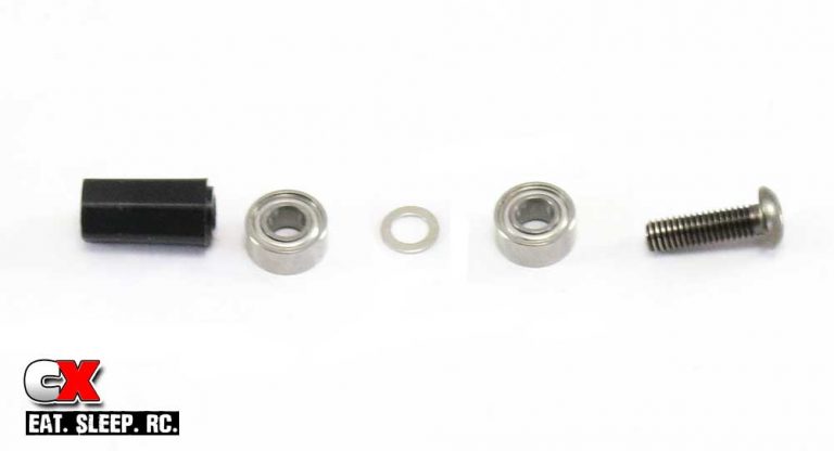
Assemble the last belt tensioner. Note the orientation of the large black spacer. Do not overtighten.
Step 6:
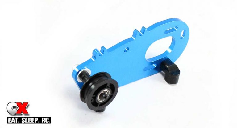
Attach the two chassis mounts to the motor plate. Attach the pulley tensioner to the motor plate (manual location – in the middle of the slot).
Step 7:
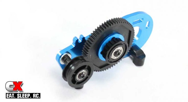
Attach the spur gear assembly to the motor mount.
Step 8:
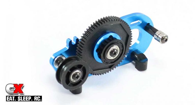
Attach the belt tensioner to the motor mount (the manual location – in the middle of the slot).
Tamiya TA07 Pro Online Build – Part 4
Tamiya has included a pair of fluid-filled gear differentials with the TA07 Pro. They work great and include high-quality internal pieces and a gasket to prevent leaking.
Build Notes:
• We’ll be using diff fluids in this step, so I suggest a nice, clean surface with some old rags in case things get messy. You are required to build two diffs, but if you’re going to install a front spool from the get-go (suggested), you only need to build one.
Step 1:
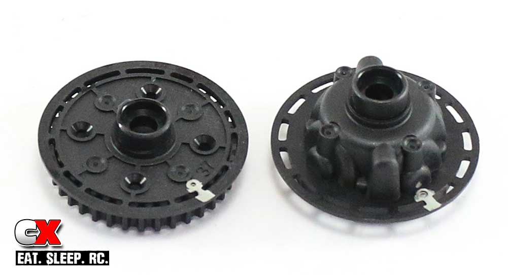
Tamiya has designed the diff halves to assemble one way and one way only. To help key them together when they’re full of gears and fluid, use a silver Sharpie to apply a small mark where the dimples are. Trust me, this will help out alot at the end of this assembly step.
Step 2:
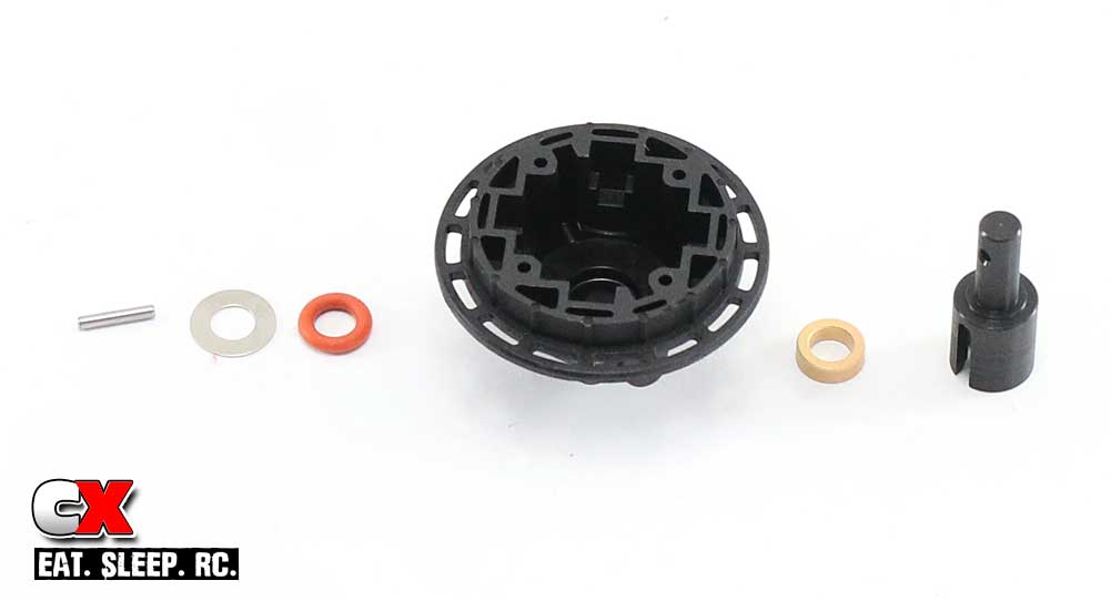
Assemble the large side of the diff half; outdrive, metal bushing, diff housing, red o-ring, washer and cross pin.
Step 3:
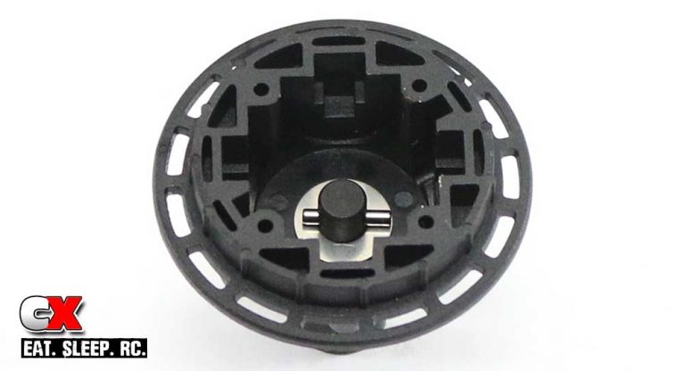
Here is what the finished assembly should look like.
Step 4:
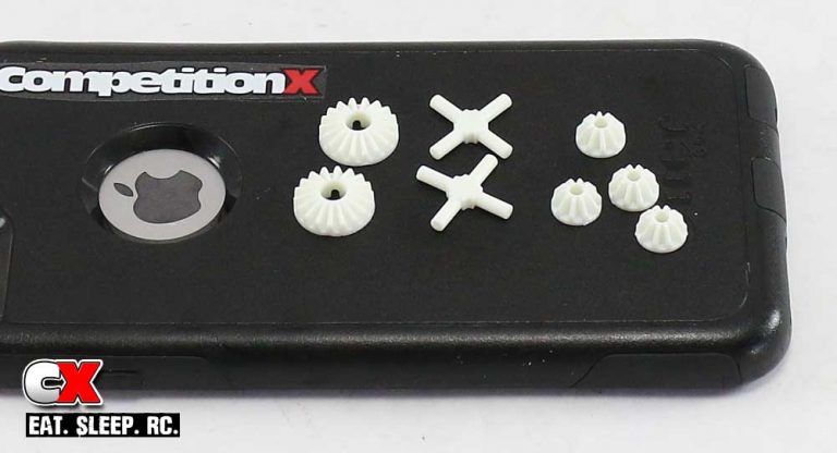
Gather the plastic diff parts and remove any flashing on them.
Step 5:
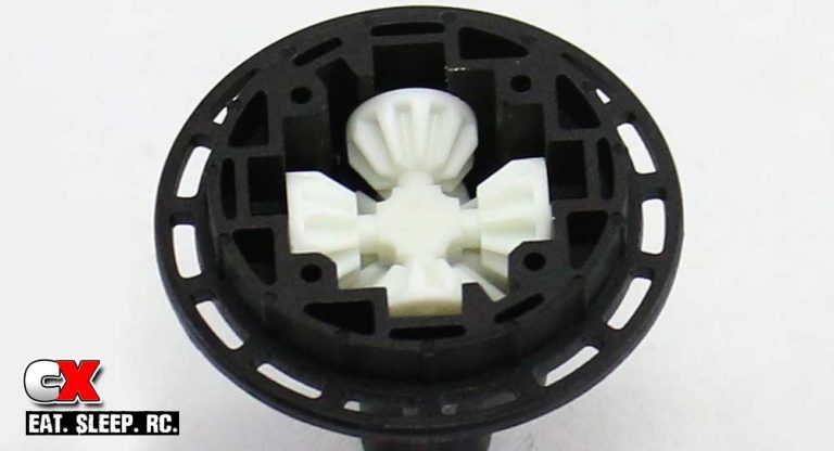
Place one of the larger satellite gears into the diff half, keying it to the cross pin. Slide four of the smaller satellite gears onto the 4-prong and set the assembly into the diff housing. Press the 4-prong satellite assembly down while spinning the outdrive to seat all the gears.
Step 6:
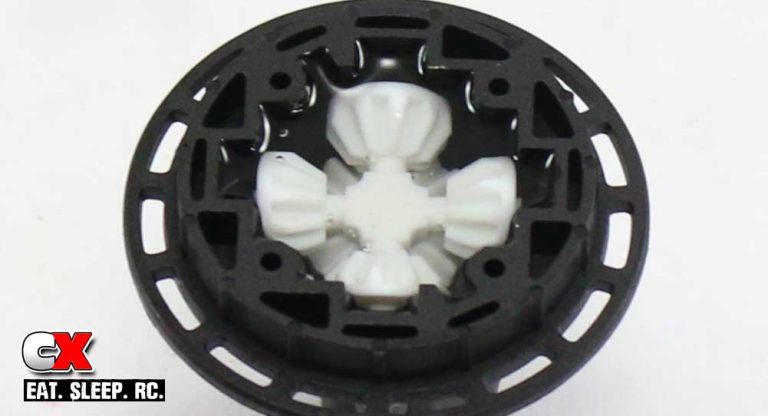
Pour quality diff fluid into the diff housing, just a little at a time. You want to make sure the fluid gets into all the nooks and crannies. Fill to the top of the smaller satellite gears.
Step 7:
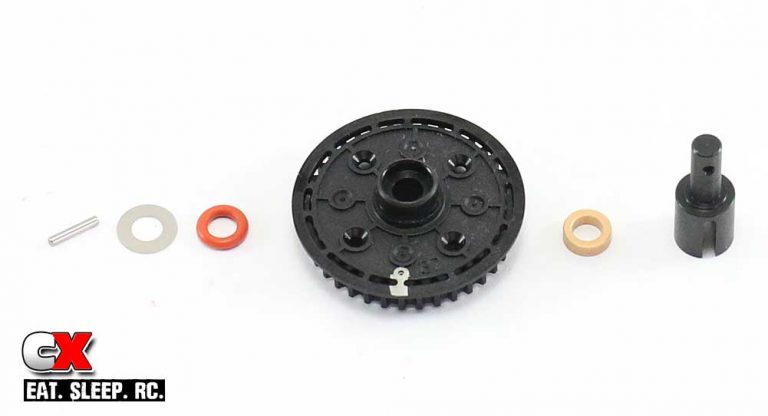
Assemble the other side of the diff unit; outdrive, metal bushing, diff housing, red o-ring, washer and cross pin.
Step 8:
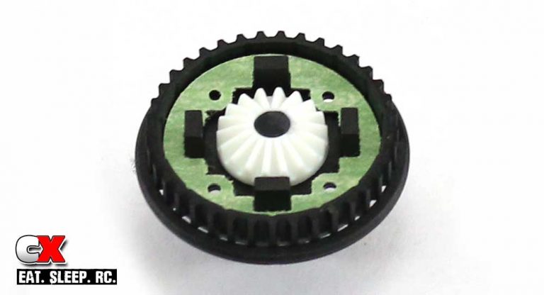
Here is what the finished assembly should look like. At this time you can also attach the gasket.
Step 9:
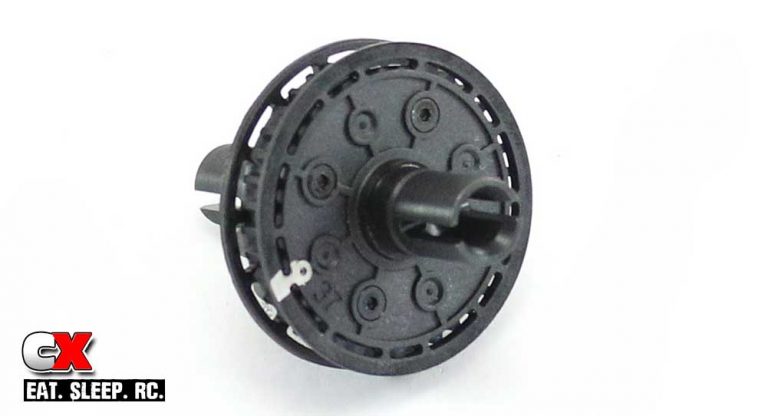
Assemble the two diff halves together, lining them up with the silver marks you applied in Step 1. The marks make it extremely easy to see instead of fumbling around. Secure with the four 2x8mm screws.
Step 10:
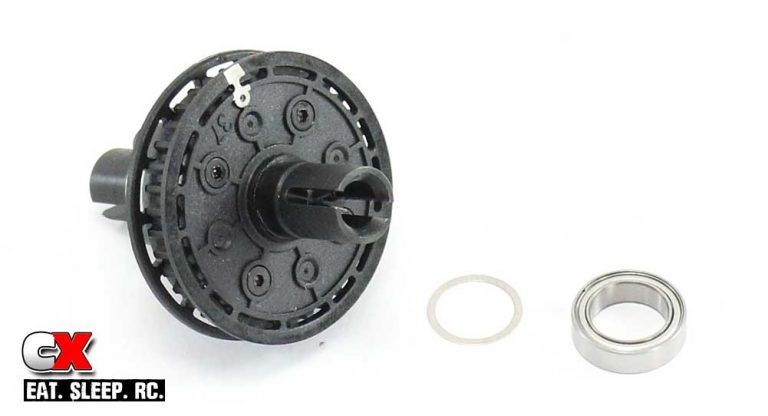
Slide one of the 10x13x.2mm shims and large bearing on each side of the diff half.
Did you make a mess with the diffs? No? Great! Let’s attach the motor mount and add the drive belt.
Tamiya TA07 Pro Online Build – Part 5
In this step we’ll be attaching the motor mount assembly, installing the front and rear diffs as well as the single serpentine drive belt. Tamiya has designed the TA07 Pro to allow three different mounting positions for the motor mount; we’ll be using the furthest back position to start.
Build Notes:
• The TA07 Pro uses a single drive belt that winds its way through a series of pulleys. When assembling, take extra care not to crimp the belt as this will certainly cause some major drive issues.
Step 1:
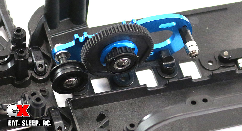
Start off this step by test fitting the motor mount to the chassis. You want the plastic mounts attached to the aluminum plate to be ‘square’ with the chassis. Once you’re happy with the mounts, attach the assembly to the chassis.
Step 2:
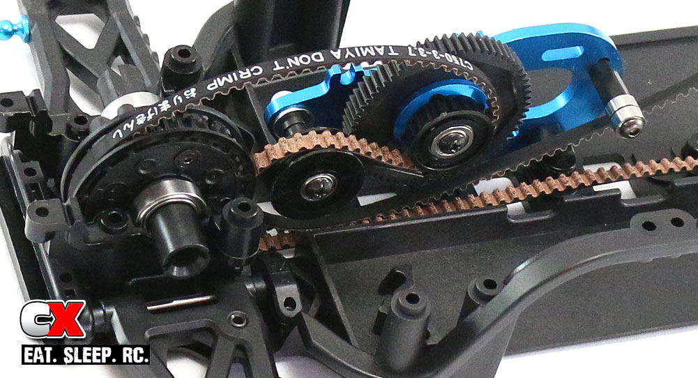
Wrap the belt around the rear diff and slide it into the rear bulkhead. Continue to feed the belt around the spur gear and pulleys as shown, being careful not to crimp it.
Step 3:
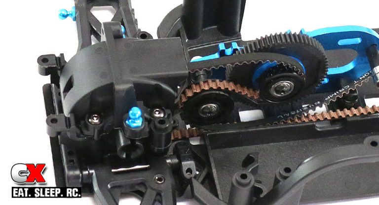
Attach the rear bulkhead cap. You can, at this time, tighten the bulkhead screws under the chassis as well.
Step 4:
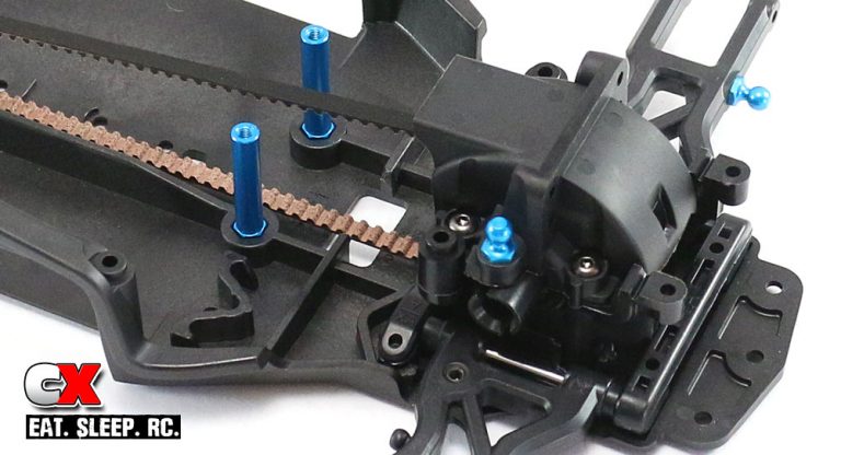
Wrap the belt around the front diff and slide it into the front bulkhead. Attach the front bulkhead cap. You can also tighten these bulkhead screws from under the chassis as well.
That was a pretty easy step, right? The manual-suggested tension is a good starting point, but you can adjust it with one or both of the tensioners on the motor plate. Next up – the steering!
Tamiya TA07 Pro Online Build – Part 6
Tamiya’s TA07 Pro uses a bearing-equipped, dual-bellcrank steering system as well as TRF blue turnbuckles and aluminum ball ends. These are nice upgrades for this level of touring car.
Build Notes:
• None.
Step 1:
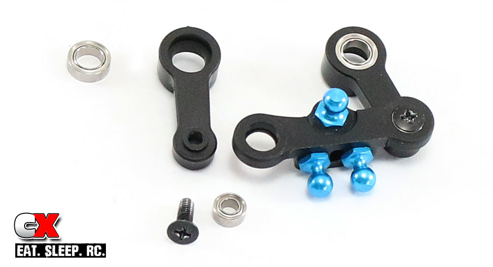
Assembly of the dual-bellcrank system is very easy – start by attaching the three blue ball ends to the steering link as well as pressing the smaller bearings into the pockets from the top. Using the 3x8mm screws, attach the steering arms to the steering link, but be careful not to overtighten these. Finish this off by pressing the two larger bearings into the steering arms from the top. The entire system should swing freely.
Step 2:
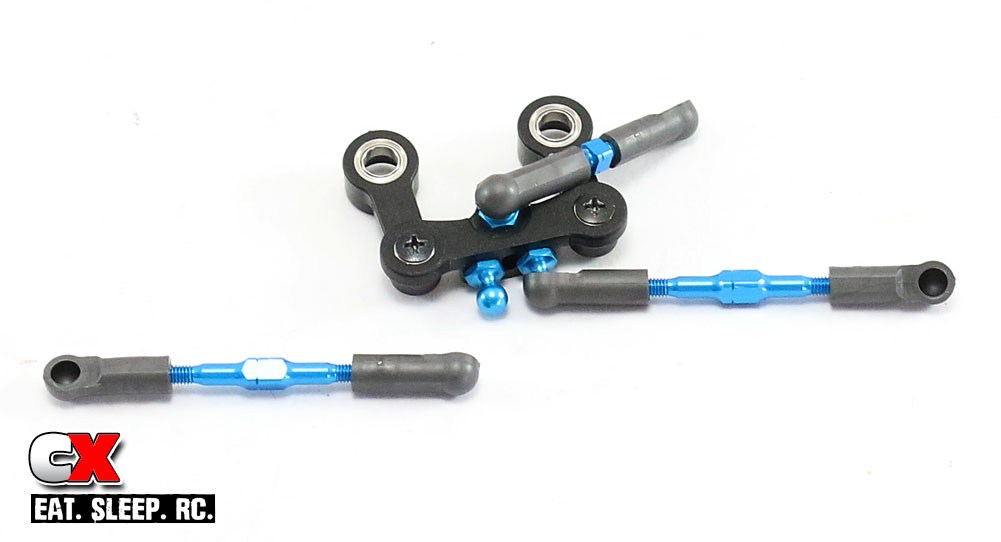
Build the two long steering turnbuckles and the drag link – the manual-suggested lengths are a good starting point. Pop them onto the ball ends as shown. A Pro tip is to make sure all the notches on the turnbuckles all face the same direction. This will make it easy when it comes to making adjustments.
Step 3:
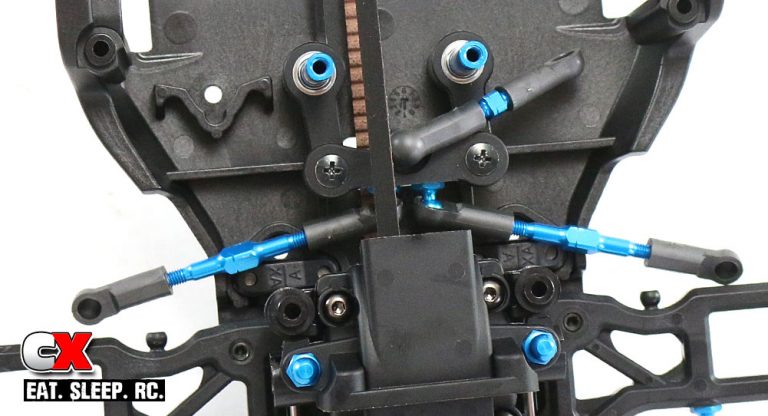
Feed the steering assembly through the front belt and slide it onto the steering posts. Again, make sure everything swings freely.
Step 4:
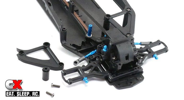
Slide the plastic spacers onto the steering posts and attach the upper chassis braces.
Another super easy step, right? Again, do a quick check to make sure the steering swings freely and let’s move on to the next step.
Tamiya TA07 Pro Online Build – Part 7
As mentioned earlier, Tamiya uses TRF419 suspension parts on the TA07 Pro. In addition, universal drive shafts are located at all four corners as are blue aluminum ball ends and spacers. High-quality bearings are also used for super smooth rolling action.
Build Notes:
• The hinge pins that go through the caster blocks and rear hubs have a flat spot on them and use a set screw to secure them. There is a thin sheet of plastic that blocks this set screw hole, so you’ll need to break through that plastic before inserting the set screw.
Step 1:
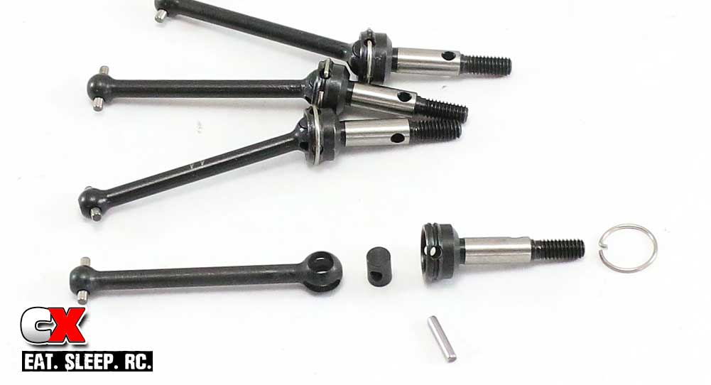
We start off this step by assembling all four universal drive axles. Slip the barrel into the dogbone, apply some black grease and fit it into the axle. Slide the cross pin through the holes in both the axle and barrel.
Step 2:
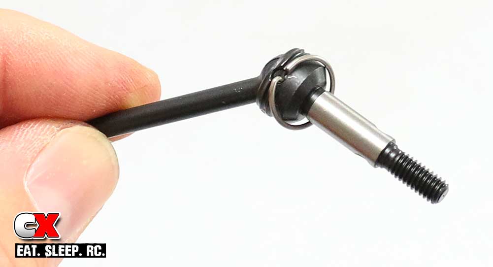
Tamiya uses a keyed ‘hoop’ to secure the cross pin. The easiest way to install this is to ‘catch’ the hole with the hooked end and slowly feed the hoop (hooked end first) into the groove. Sounds complicated, very easy to do. Build four.
Step 3:
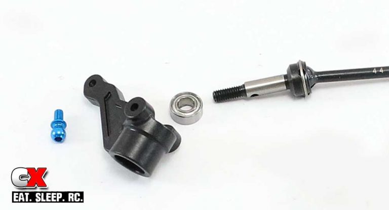
Insert the blue ball end into the steering arm (from the bottom), then insert a bearing and the assembled universal drive axle. Build the other side, just make sure it’s facing in the opposite direction.
Step 4:
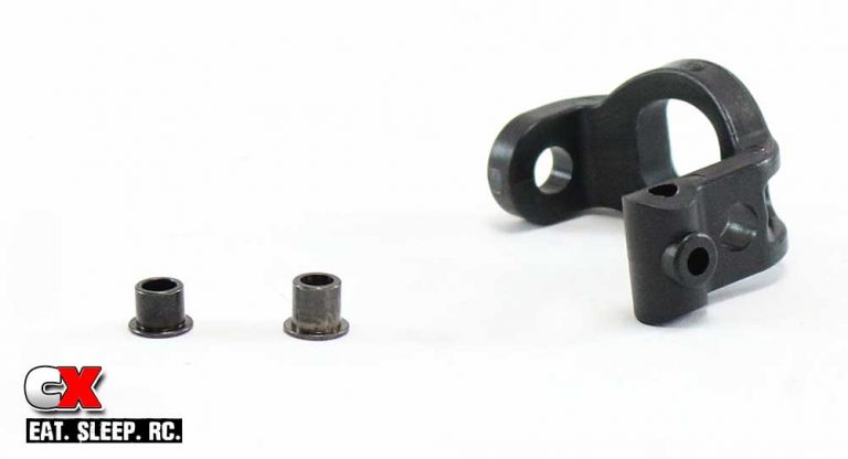
Before inserting the hat bushings into the caster blocks, take note that they are different in size; short and tall. The short one will go into the upper hole, the tall one into the lower hole.
Step 5:
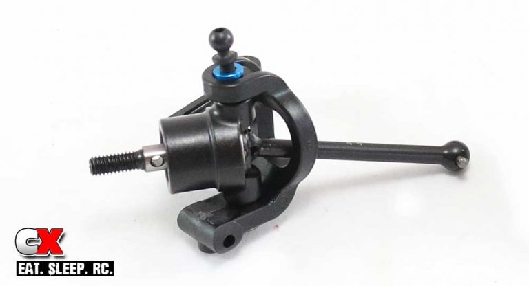
Once you’re inserted the hat bushings, slide the universal axle through the caster block, then align the holes and secure with the 3x10mm screw (at the bottom) and 5x8mm ball stud up top. Don’t forget the .5mm blue washer on top.
Step 6:
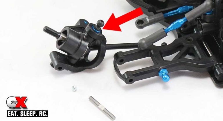
Insert the set screw into the hole on the bottom of the caster block; only feed it in a short ways. Slip the assembled steering arm into the suspension arm, then insert the hinge pin. Note the flat spot on the pin; it should be facing down so when you tighten the set screw, it can lock the hinge pin in place. Pop the steering links onto the steering arm, then build and install the camber links. The arrow is pointing out the blue washer – make sure you have installed it here.
Step 7:
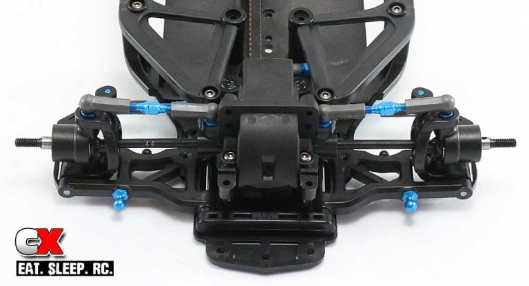
Here is a look at the completed from end.
Step 8:
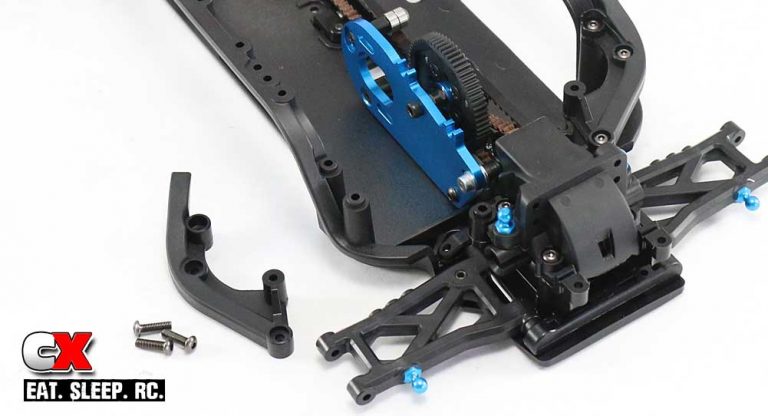
Moving to the rear, attach the rear chassis braces.
Step 9:
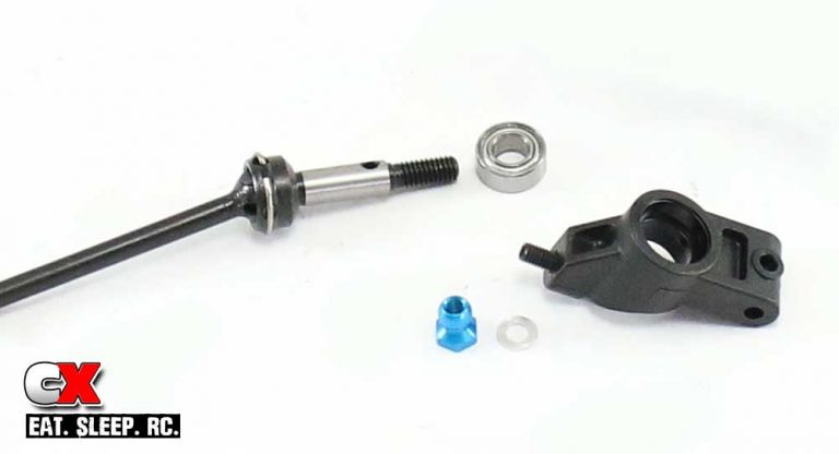
Build both rear hubs; start by inserting the 3x10mm set screw into the rear hub followed by the 1mm silver shim and blue ball connector. Press the bearing into the hub (from the back) and slide the universal axle into place.
Step 10:
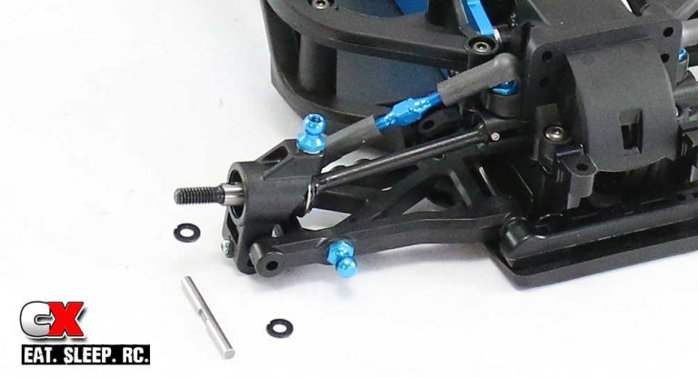
Insert the set screw into the hole on the bottom of the caster block; only feed it in a short ways. Slip the assembled rear hub into the suspension arm, then insert the hinge pin making sure to include a wheelbase shim on both sides of the hub. Note the flat spot on the pin; it should be facing out towards the set screw. Tighten down the set screw. Build and install the camber link; match the direction of the notch on the turnbuckle with those on the front of the car.
Before moving on, make sure the suspension moves freely up and down. When you’re happy with it, we can move on to the next step – the shocks.
Tamiya TA07 Pro Online Build – Part 8
One area Tamiya has the edge on the competition and that’s their amazingly smooth shocks. The TA07 Pro comes with a full set of TRF dampers – an awesome addition that racers will love!
[box type=”info” align=”aligncenter” class=”” width=””]
Build Notes:
• As with any builds, the shocks can be a pretty messy step at times. Be sure to have a clean area with some extra rags available to clean up any spilt fluids.
Step 1:
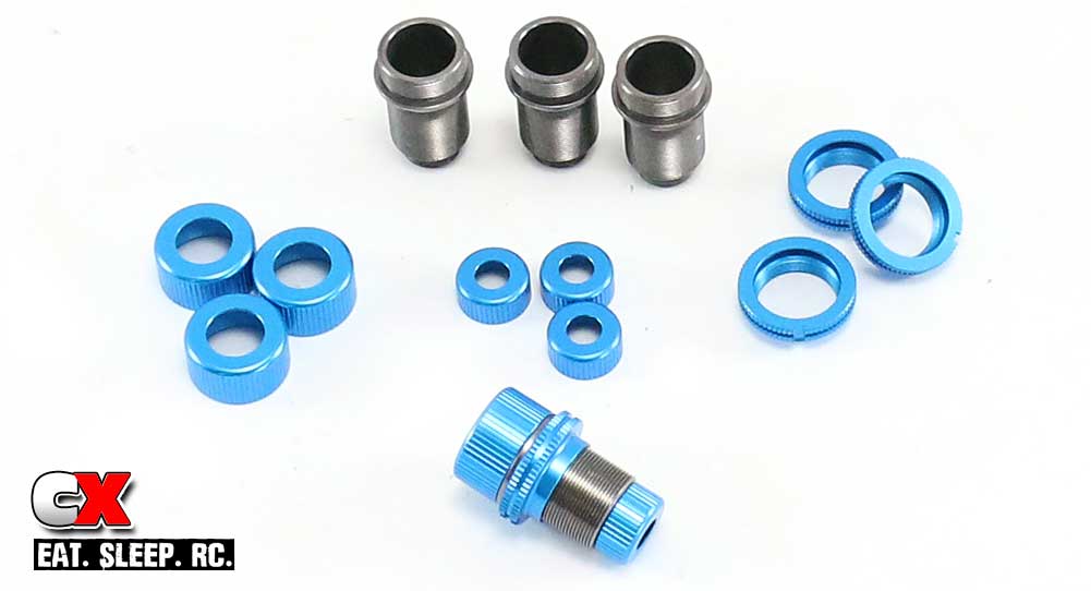
Tamiya’s shocks come pre-assembled, so you’ll need to separate everything before building.
Step 2:
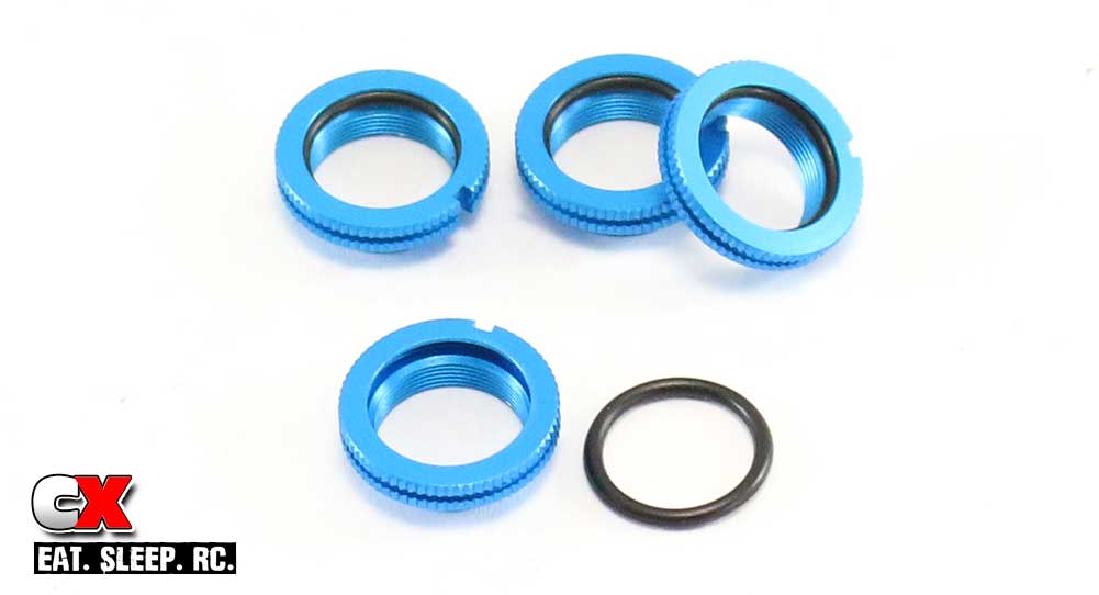
While this is a bit out of order, I always install the o-rings into the collars before anything else. Once your hands get any type of oil on them (and then transferred to the o-rings), this step can become a nightmare. Dry o-rings are easier to install.
Step 3:
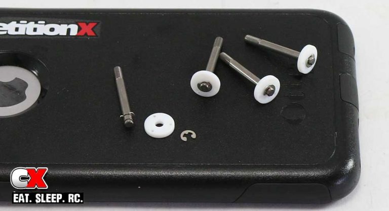
Snap an e-clip into the bottom groove on the shock shaft followed by the white pistons. Secure the piston by installing another e-clip into the top groove.
Step 4:
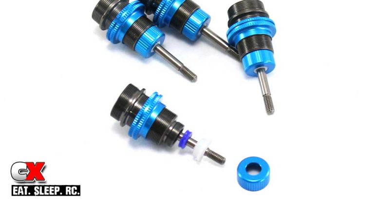
Place a small drop of oil on to the shock body, then feed the threaded collar on. Slide the assembled shock shaft down through the shock body, then apply a small drop of shock fluid onto the threads. Slide the blue o-ring and bottom plastic retainer on to the shaft and up into the bottom of the shock body, then install the bottom retainer cap.
Step 5:
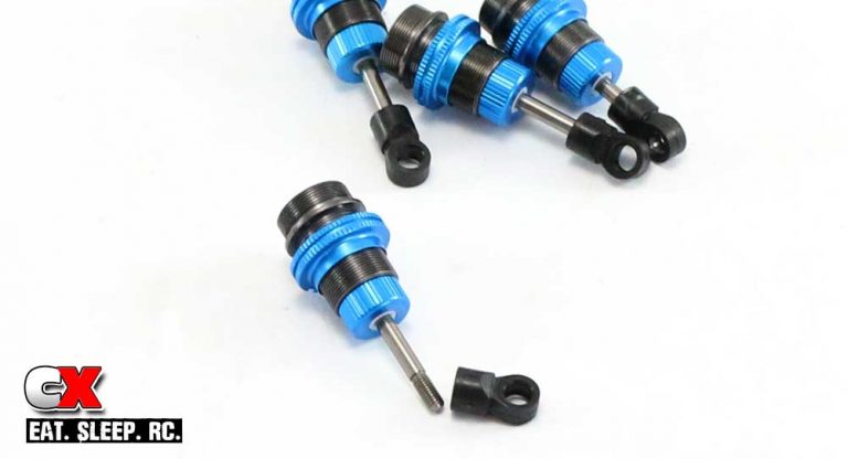
Attach the lower shock eyelet. Screw on until the threads on the shaft disappear. Make all four shocks equal length.
Step 6:
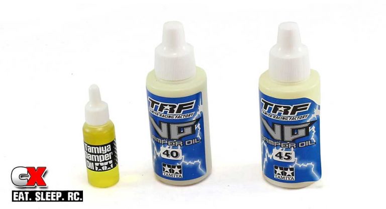
Tamiya usually supplies it’s kits with their generic yellow damper oil. This is ok for cruising around the cul-de-sac, but for performance purposes we’ll need to put some high-end fluids in. I’m opting for 45wt and 40wt oils, both from Tamiya’s TRF line.
Step 7:
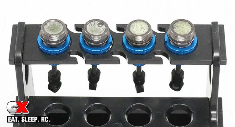
Fill the shocks up with oil. Slowly move the shock shaft up and down to release any air bubbles, placing them in a shock stand to allow the bubbles to disperse. As you can see, there’s quite a few bubbles in these shocks. Also, if you are using different shock fluids, make sure you mark the shocks so you don’t get them mixed up.
Step 8:
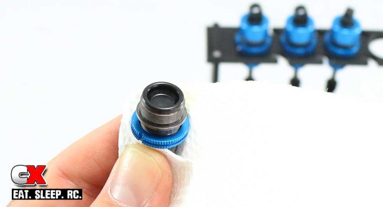
Once all the bubbles are gone, re-fill the shock to just below the top (if needed). When placing the rubber bladder on top, it will probably displace some of the oil; this is fine. Just make sure the bladder seats correctly on top of the shock (as shown in the photo).
Step 9:
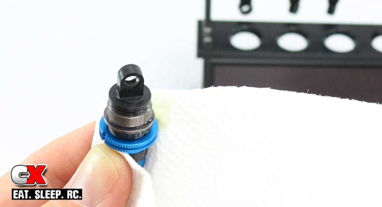
Place the plastic cap on top of the bladder…
Step 10:
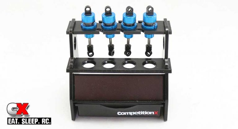
…and screw the aluminum shock cap on. Once done, you’ll have four little silky smooth dampers!
Step 11:
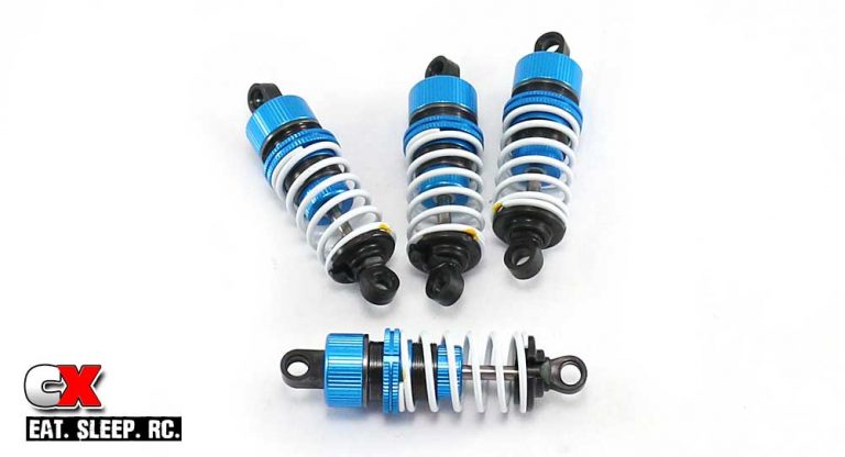
Slide the springs on and capture with the lower spring retainers.
Step 12:
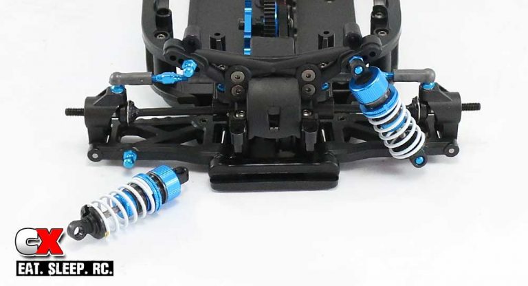
Assemble the rear shock tower and attach it to the diff bulkhead cap. Pop the shocks onto the blue ball ends.
Step 13:
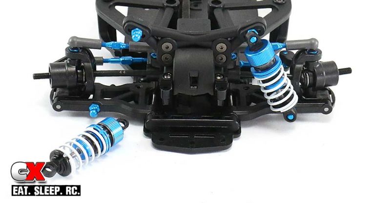
Assemble the front shock tower and attach it to the diff bulkhead cap. Pop the shocks onto the blue ball ends.
The shocks are done! Clean up your mess and let’s get to the next section – the electronics!
Tamiya TA07 Pro Online Build – Part 9
Being a ‘Pro’ kit, the Tamiya TA07 Pro doesn’t come with any electronics, not even the Tamiya ESC or Mabuchi motor. That’s fine as this is a race-level kit and not including those helps keeps the price down. It also allows the builder to drop in any electronics they want. We’ll be installing some Futaba and HobbyStar components in our TC.
Build Notes:
• Before installing the electronics, it’s a good idea to fire them up outside the car. This will let you center the servo and make sure everything is in proper working order.
• Be mindful when clipping the ESC wires for installation; remember, the motor mount can be moved to one of three locations on the chassis and if you chop the ESC motor wires to short, you may need to replace the wires for them to reach it.
Step 1:
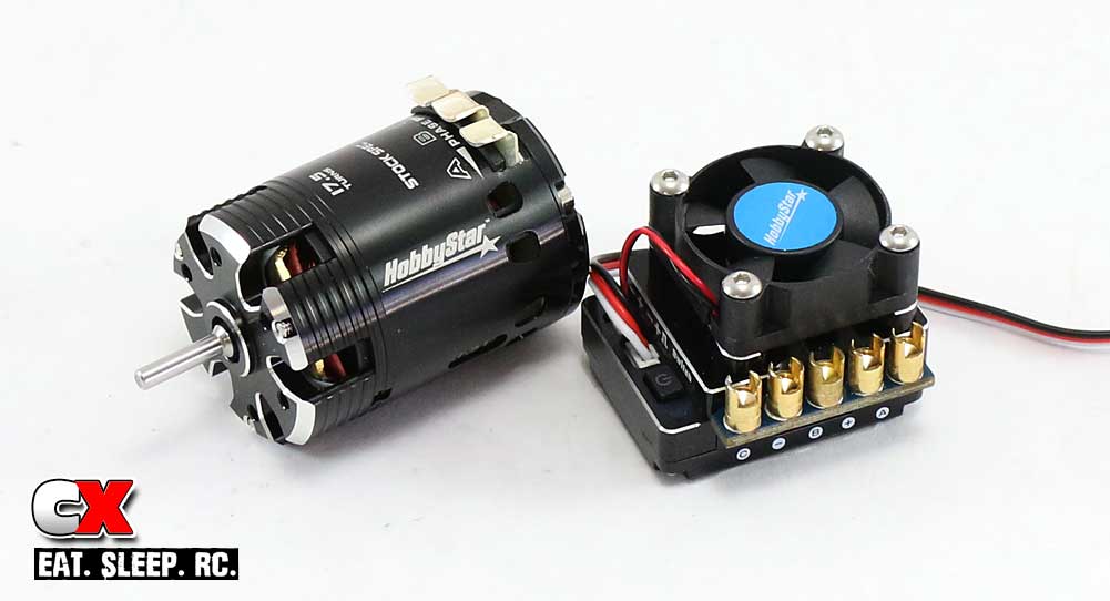
CompetitionX has recently hooked up with HobbyStar, so we’ll be installing their top end 120A Turbo Competition ESC and 17.5T sensored Spec motor. Both of these are great looking products and did exceptionally well in our initial test. For more info on them, you can read our review of the Tamiya TA07 Pro that used the HobbyStar electronics. Go ahead, read it. I’ll wait.
Step 2:
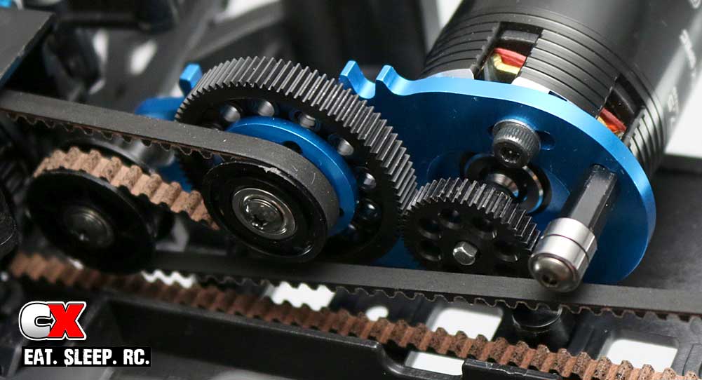
Now that you’re back from reading the review, let’s go ahead and install the HobbyStar motor. As you can see in this photo, we’ve already swapped out the .6 Mod gears with 64P and I’ve already matched up the suggested gearing for the Tamiya track. Set the mesh and tighten down the motor screws.
Step 3:
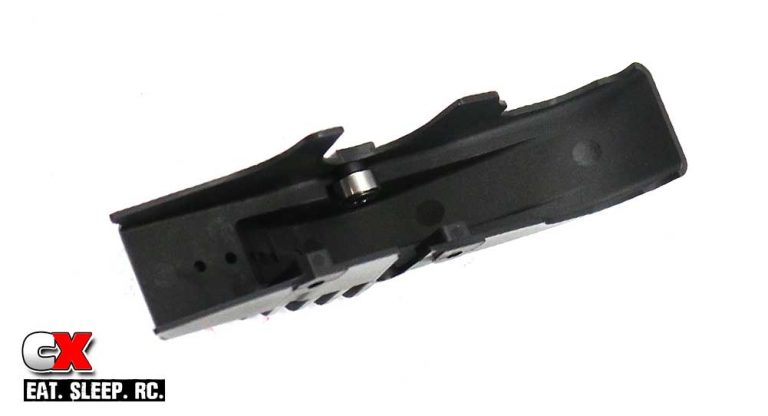
Install the belt bearing into the spur gear cover. Do not overtighten.
Step 4:
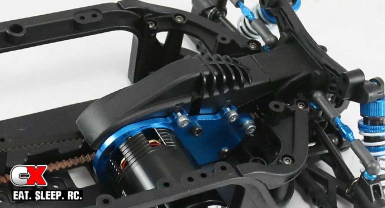
Install the spur gear cover. I found it easier to insert the screws into the cover, press the assembly into place and tighten the screws.
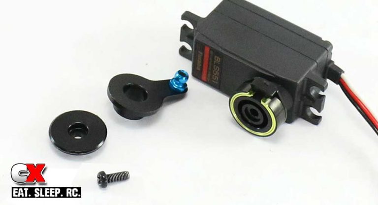
Step 5:
Attach the servo-mounted servo saver to your servo (that’s a mouthful). The TA07 Pro has provisions for either a standard or shorty servo; I chose the shorty so I could mount all my electronics right on the chassis deck.
Step 6:
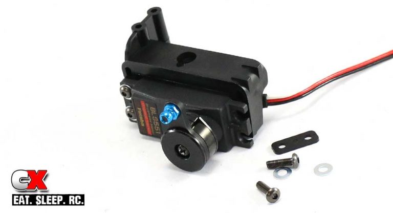
Attach the servo to the floating servo mount.
Step 7:
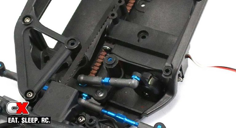
Install the servo assembly into the TA07, then pop the drag link onto the servo. If you are using a standard servo, you need to attach the additional antenna holder. If using a shorty servo, skip that step. As per the manual, I found it MUCH easier to install once I removed the chassis brace.
Step 8:
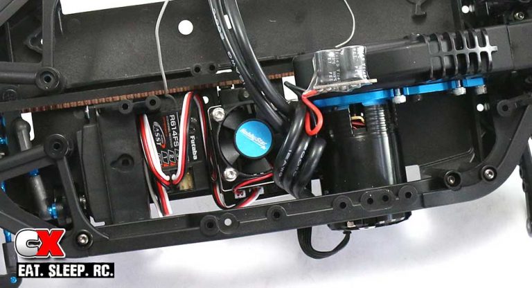
Space is a little tight for the electronics, so you might have to be a little creative with your wiring. This is how I had to set it up, with the additional capacitor taped to the spur gear cover. Strange, but it works.
Step 9:
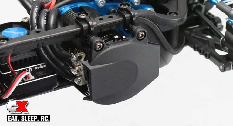
Once all the wires are routed and connected, assemble and attach the motor guard.
Step 10:
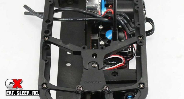
The final step is to attach the upper deck plate. Feed the antenna wire through the hole and screw the 2-piece unit into place.
Great job. I know this is a tricky step with the limited amount of space for electronics, but I’m sure your car looks great.
Tamiya TA07 Pro Online Build – Part 10
The final step in the Tamiya TA07 Pro build are the tires, wheels, body mounts and final battery tray assembly. The battery tray will be the oddest to build as it has to conform to the strange upper deck, but the final result is extremely sturdy.
Build Notes:
• There are multiple variables with this final step; wheel and tire combos, LiPo battery sizes and body styles that will require you to trim the foam bumper. Finish off the final steps carefully so your finished product will be complete and the way you want it.
Step 1:
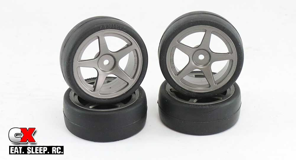
Since I’ll be driving the TA07 Pro primarily at the Tamiya track, I opted to install a set of the B3 pre-mounted race tires. They work great at this track and, well, they’re pre-mounts so all I have to do is pull them from the package and slap them on the car. Done.
Step 2:
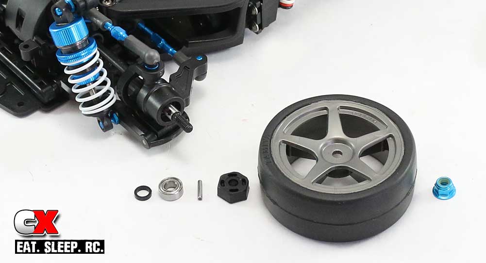
To install them, we need to first finish the axle assembly. Slip a plastic ‘crush tube’ on to the axle followed by a wheel bearing and cross pin. Slide the plastic wheel hex on to the axle and key it to the cross pin. Install the tire and secure it all down with the blue wheel nut. Repeat on all four corners.
Step 3:
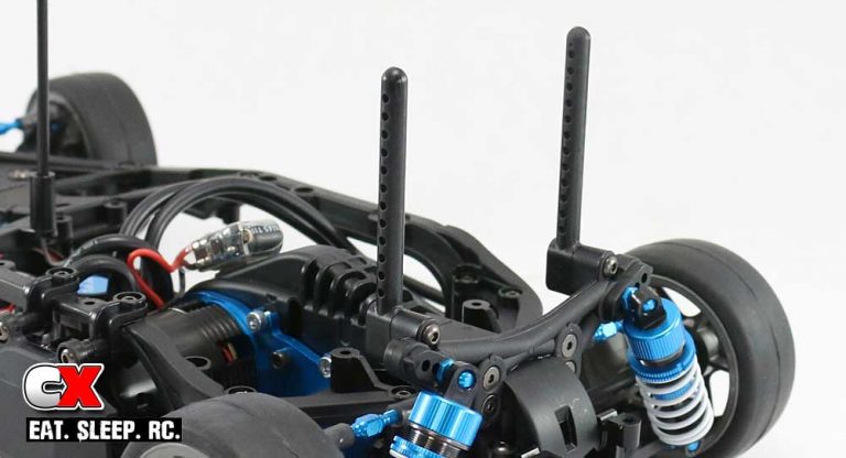
Attach the rear body posts.
Step 4:
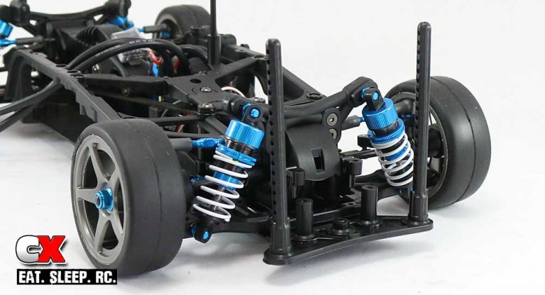
Attach the front body posts to the lower bumper, then attach that assembly to the car.
Step 5:
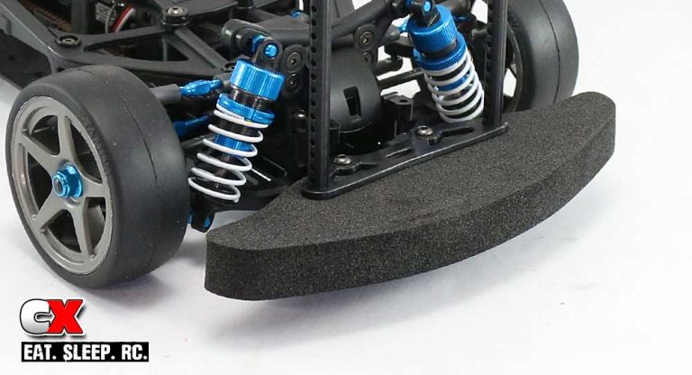
Slip the foam bumper into place and secure with the upper bumper plate. Some trimming of the foam bumper might be needed depending on the body you will be running.
Step 6:
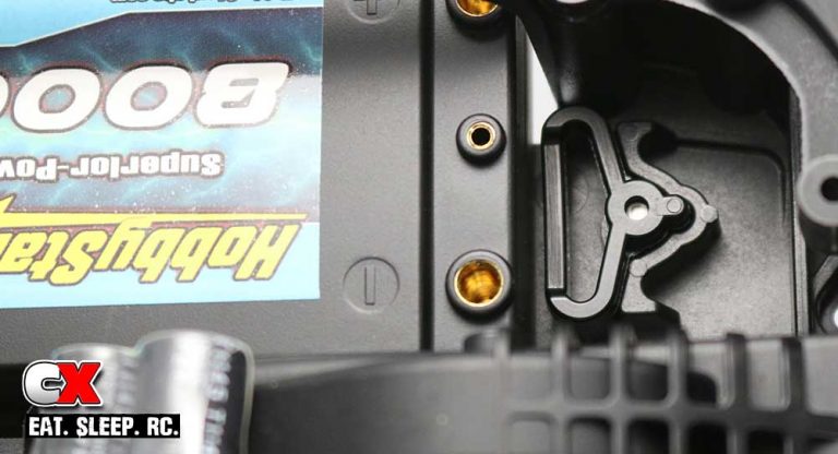
Attach the battery stops to each end of the battery box. Here’s a close up of how much room is available between my particular battery and the stop; you can fill this space with the sticky-backed foam pad included with the kit.
Step 7:
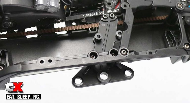
Attach the battery holder. This holder comes with various spacers to properly fit it to the LiPo battery you will be using. Build it per the manual, then test fit your battery. You can add or remove the shims based on this fitment.
Step 8:
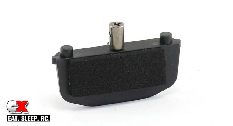
Assemble the battery door. Use some of the sticky-backed foam to help keep the battery firmly in place when the door is attached.
Step 9:
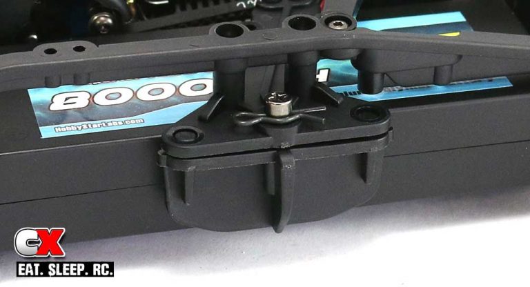
Slip the battery in followed by the battery door. Secure the door with a body clip.
Step 10:
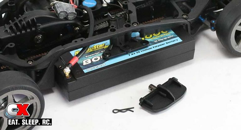
There’s a problem with this chassis setup when using batteries with bullet plugs. As you can see, the outside connector hole resides under the upper chassis rail, making it impossible to insert the plug with the battery installed. Here’s a quick tip; partially insert the battery, then connect the furthest lead as shown (in my case, the furthest lead was the positive one). Now slide the battery all the way in and lock it in place with the battery door. You’ll need to do this step in reverse to remove the battery.
And just like that, you’ve got a completed Tamiya TA07 Pro Touring Car. The final steps will be to paint and mount a body – you’ll also need to attach the body mount pins however their location will be dependent on which body you run.
Now charge that pack and let’s go drive! Good luck.

