

Team Associated Factory Team F6 Online Build

I love all kinds of motorsports, but Formula 1 is probably my favorite. The cars are wicked fast, look amazingly sleek and can corner faster than anything else out there.
I guess that’s why I really love the 1:10 scale F1s as well. So, of course, there’s no surprise that I had a grin on my face from ear to ear when I heard Team Associated was seriously thinking about jumping into the F1 arena. Then there was the rumors of an actual car spotted at the track. Finally, a press release filled with lots of pictures.
So here we are, mere months after the sneak peek photos swept the internet, I have a production F6 sitting on my bench awaiting a build.
UNBOXING VIDEO
Team Associated Factory Team F6 Online Build – Part 1
Team Associated’s F6 is very similar to a now-age pan car; it uses a single center shock and a pair of side dampers to control movement. A pair of side springs help control compression, but we’ll be installing those at a later time. This step is all about assembling the center shock, dampers and turnbuckles.
Build Notes:
• Since we’ll be working with oils, it’s recommended that you have a clean work space and a few clean towels handy for quick cleanup.
• You’ll also need some sort of shock stand for this step of the build. This will allow you to set the shock aside for a few minutes to allow the bubbles to rise out of the oil.
Step 1:
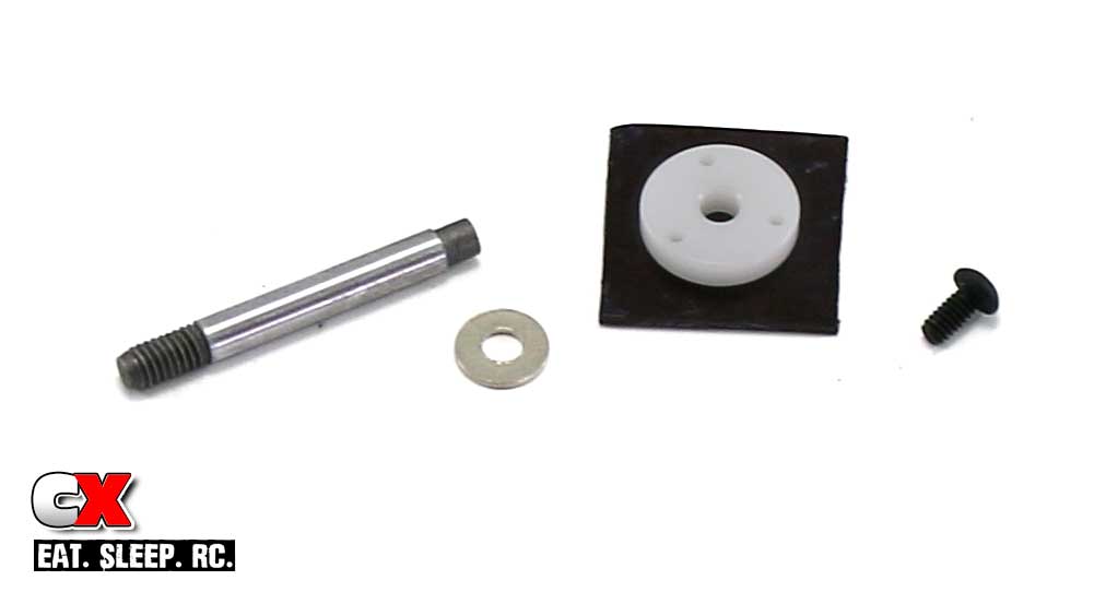
I’ve laid out the parts for the shaft/piston build. Slide the steel washer over the un-threaded end of the shock shaft followed by the piston. Secure it with the 2x4mm screw. A very light dab of threadlocker will help keep this screw in place.
Step 2:
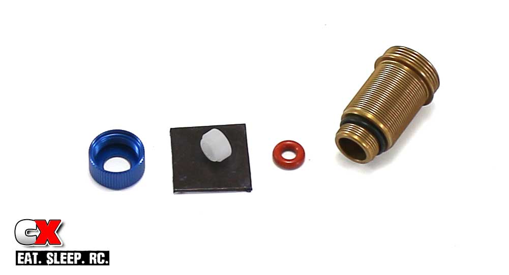
The next step is to assemble the shock body. Start by sliding the small black o-ring over the end of the shock. Press the red o-ring and shock bushing into the small end of the shock followed by the shock bottom cap. Note the orientation of the bushing; the shoulder should be facing away from the shock body.
Step 3:
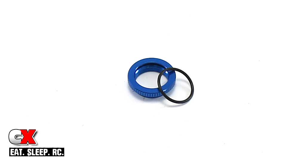
While not listed until a later step, I like to install the shock collar o-ring early. If you have any oils on your fingers and try to do this, it can become quite difficult. These parts are already available to us so doing it now isn’t that big a deal.
Step 4:
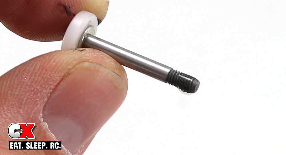
Before sliding the assembled shock shaft into the shock body, put a drop of the 30wt oil on the threads as shown.
Step 5:
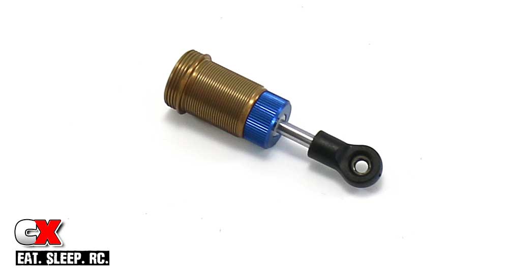
Press the assembled shock shaft slowly into the body. This will ensure you don’t damage the red o-ring. Once through, screw on the bottom eyelet and press the FT pivot ball into place.
I installed the shock collar at this time as well, only because the holes in my shock stand are too big to hold the shock without it.
Step 6:
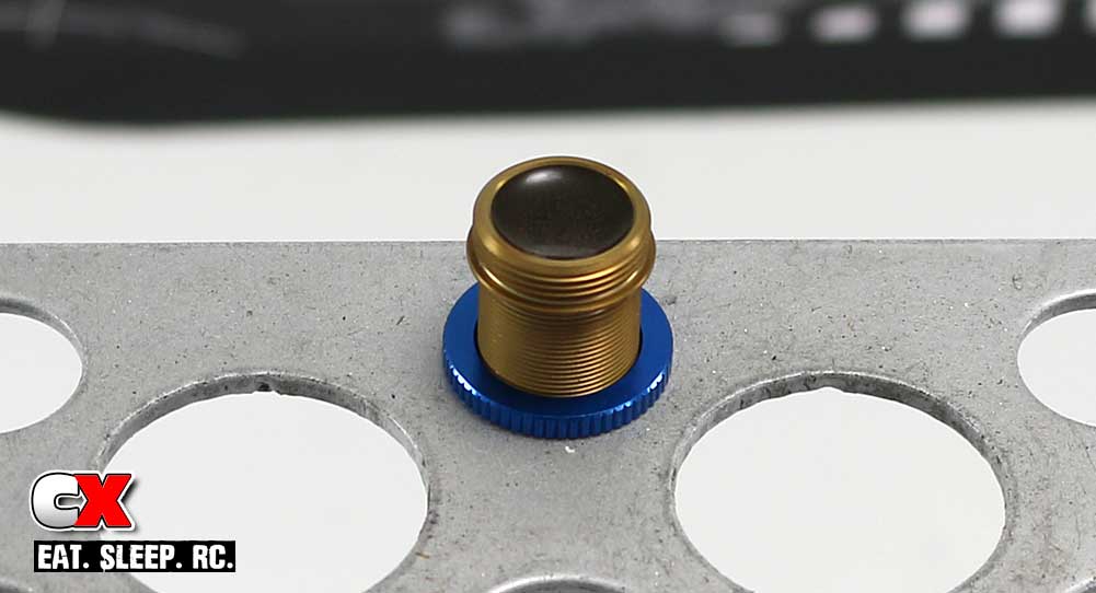
Fill the shock with oil. Once full, slowly slide the shock shaft up and down, allowing oil to pass through the holes in the piston and fill the space under it. Set the shock aside for a few minutes to let all the bubbles rise to the top.
Step 7:
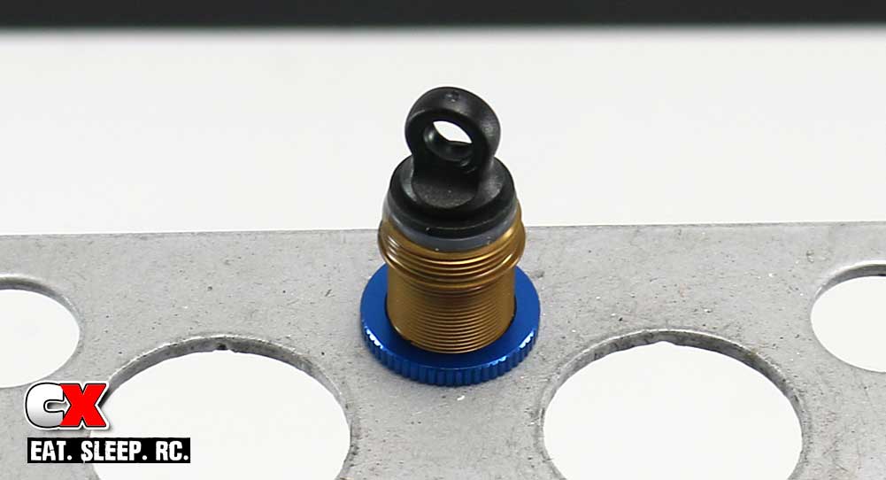
Re-fill the shock until the oil is near the top, then slowly set the bladder in place. This will most likely displace some of the oil; this is ok. Set the plastic shock cap in place.
Step 8:
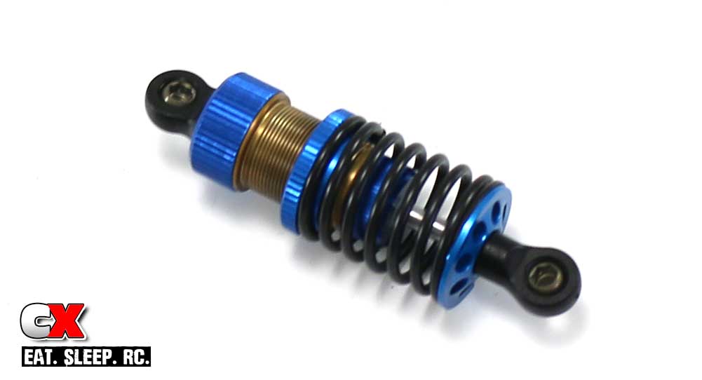
Screw the aluminum shock cap retainer onto the shock, being careful not to move the bladder. Wipe off any excess oil on the outside of the shock, then install the spring and lower retainer.
You’ll want to make sure the center shock is 64.8mm in overall length (per the manual). Adjusting this length sets the rear pod droop on the F6.
Step 9:
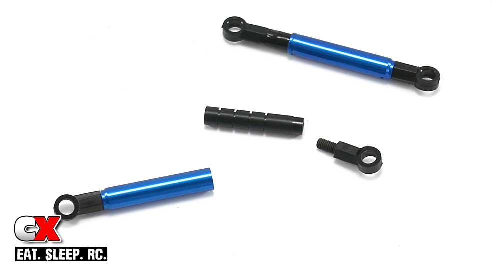
Assemble the pair of side dampers. Place a drop or two of the 10K fluid on the damper tube shaft and use your fingers to spread it around evenly. Slide the 2 halves together; there will probably be a little residual fluid on the outside of the tube; just wipe it off with one of your clean towels.
Step 10:
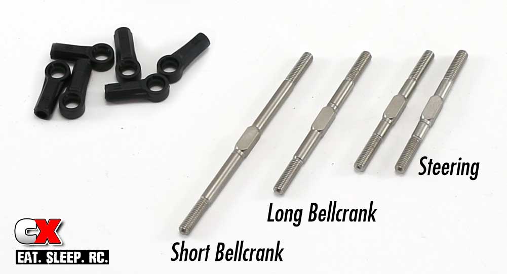
On to the turnbuckles. Note the three different lengths shown; we’ll be building the two shortest lengths (38mm, steering) and the longest length (58mm, short bellcrank). This is the kit suggested setup. If you choose to use the longer bellcrank, you’ll want to replace the long turnbuckle with the 45mm one.
Step 11:
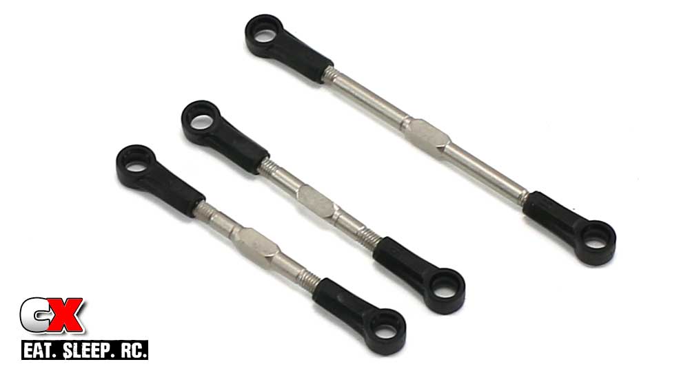
Here’s the final shot of your built turnbuckles,
Set these, the shock and the side dampers aside for now. We’ll be installing them in a later step.
Team Associated Factory Team F6 Online Build – Part 2
Part 2 of our Team Associated F6 build revolves around the steering and servo install. This car accepts both standard and forward mounted servos as well as a long or short bellcrank option. Graphite upper and lower arms are used as well.
Build Notes:
• This is the first step where graphite parts will be used; if you want to give your F6 a little more professional feel, check out our video explaining how to prep and seal your graphite parts: How To: Prep and Seal Carbon Fiber / Graphite Parts
• There’s alot going on with this front end, so pay close attention to the direction of the parts. I’ve been building for a long time and even I messed up on a couple of them.
• Many of these steps feature screws going into aluminum parts; I highly suggest blue threadlocker when attaching these. Typically I would tell you at each step, but that would get a bit redundant. It’s now in the notes.
Step 1:
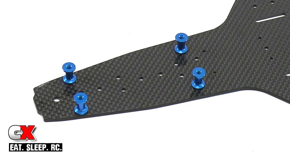
Step 1 is easy; attach the 4 suspension arm standoffs to the chassis.
Step 2:
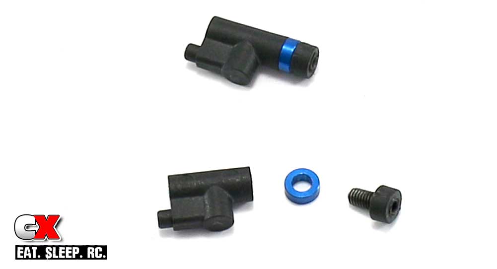
Assemble the steering stop/droop buttons. For those of you that want to be super precise (onroad car – you should be), thread the set screw just past the top of the button, then remove any flashing.
Step 3:
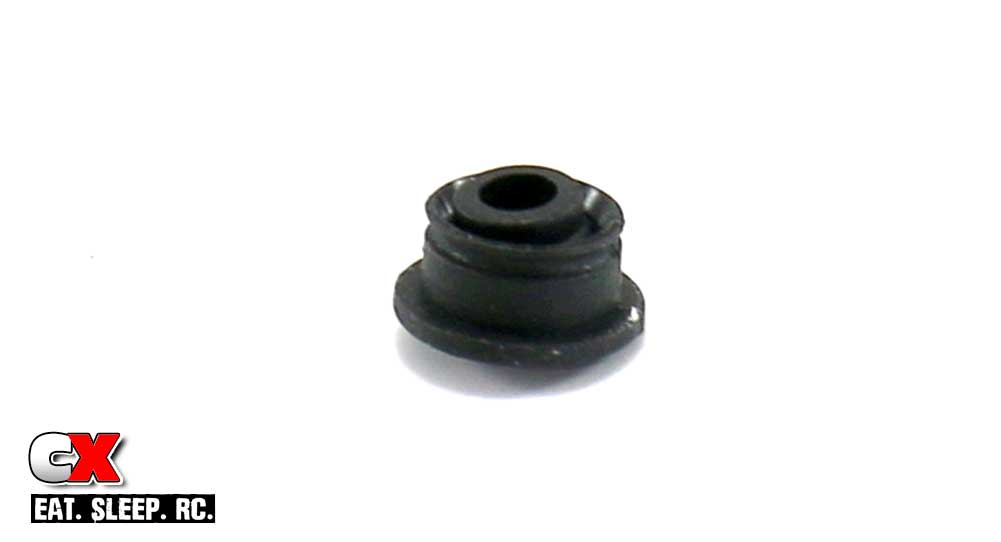
If you already opened all the bags, you’ll find the 2 suspension arm pivot balls that are different from the rest. If you havent’ done so yet, find them now before you snap the wrong ones in place. The correct ones have an extended lip on only one side; the others have extended lips on both sides.
Step 4:
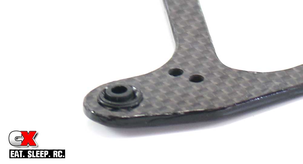
Press the pivot ball assembly into the arms as shown. They may be a little tight, that’s ok. Don’t sand away any material to make them fit or you’ll have a very sloppy suspension setup.
Once pressed through, slide the o-ring over to lock the bushing in place. If needed, use your fingernail to press the o-ring deeper into the grooves.
The manual also give the option to glue these in place; I wouldn’t suggest this just yet in case you assemble them incorrectly.
Step 5:
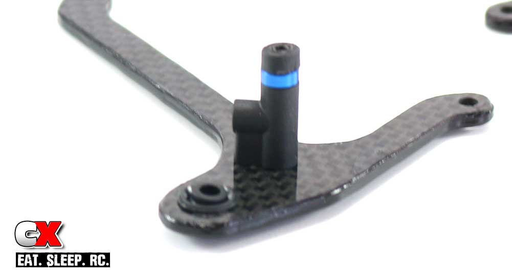
Attach the steering stop/droop assembly on both lower suspension arms.
Step 6:
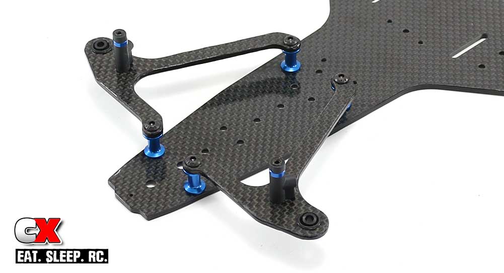
Attach the lower suspension arms to the standoffs as shown. Note the orientation of the steering stops.
Step 7:
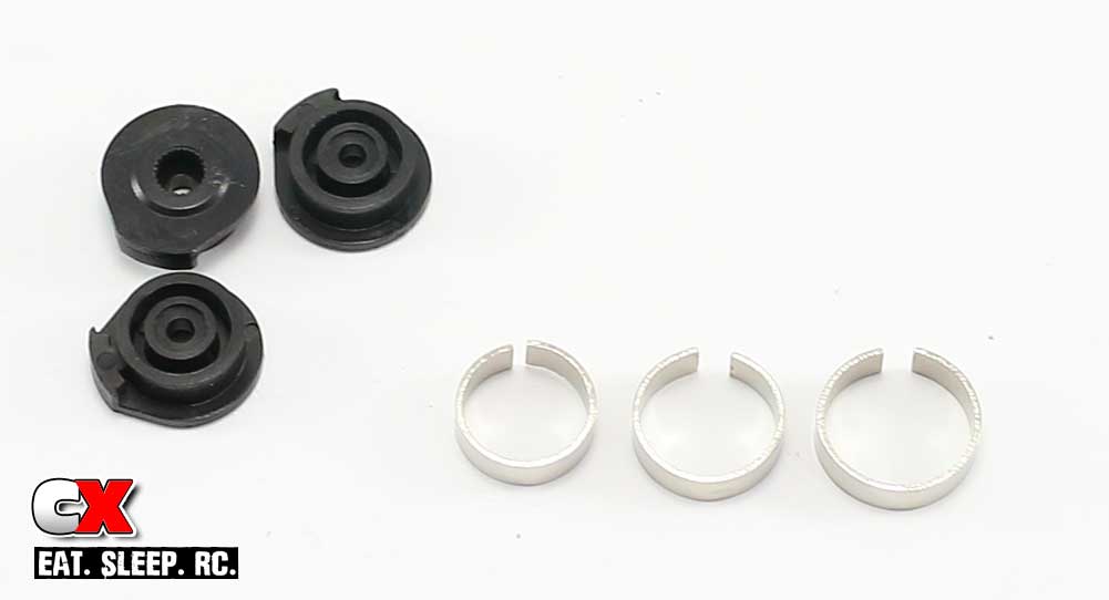
The servo saver on the F6 is not incorporated into the bellcrank but attached straight to the servo itself. It uses 3 steel clamps off different sizes.
Before assembling them, make sure you choose the correct horn for your servo. Unfortunately the horns are not marked, so you’ll have to test fit them to your servo to find out which one you need.
Step 8:
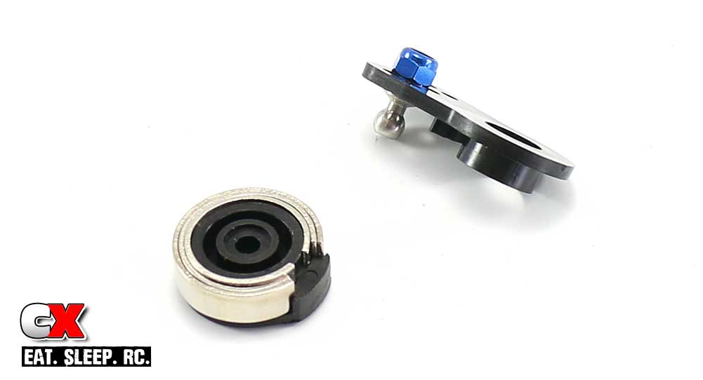
A look at the completed servo saver and steering arm. I left this unassembled so you could get a better look at how it all goes together.
Step 9:
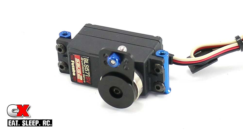
The F6 requires the use of a shorty servo. If you don’t have one, you’ll need to get one otherwise it will extend off the chassis (in the standard location) or be too tall in the forward location. I’m going with Futaba’s BLS571SV S.Bus servo – small, fast and plenty powerful.
Attach the assembled servo saver to the servo. Also at this time, go ahead and attach the servo mounts as well, however don’t tighten them down all the way just yet. Note the longer one with the ‘foot’ goes to the right.
Step 10:
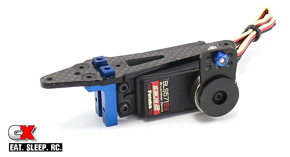
Attach the graphite top plate to the aluminum front bulkhead, then attach that assembly to the servo standoffs.
This step had me stumped for a few; note the bulkhead poking up through the graphite mount. Instructions weren’t too clear here but got it figured out.
Step 11:
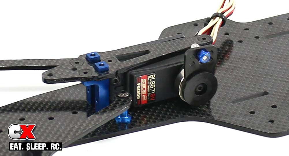
Place the servo assembly onto the chassis and secure with the 3 3x6mm screws. You can tighten up the screws from Step 9 at this point as well.
Step 12:
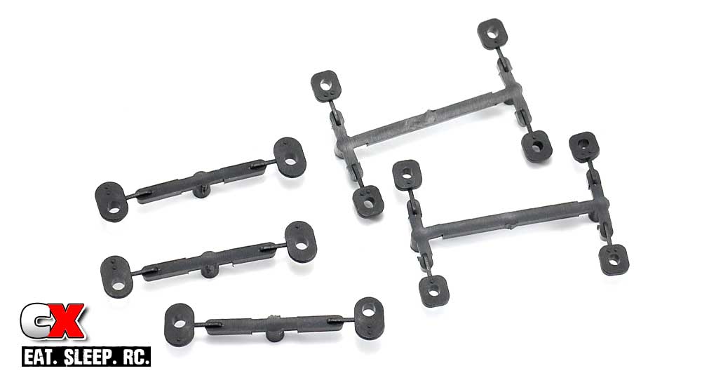
These are the plastic inserts you’ll use to tune the front suspension on the F6. They press into another graphite front top plate.
Remove the 4 1-dot square inserts and the 3 1-dot oval inserts. Clean any flashing off of them.
Step 13:
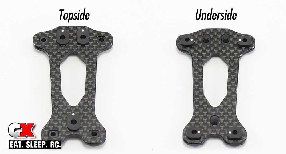
Press the inserts into place as shown. I’ve colored the dots and show both sides to make it easier to note their position.
Step 14:
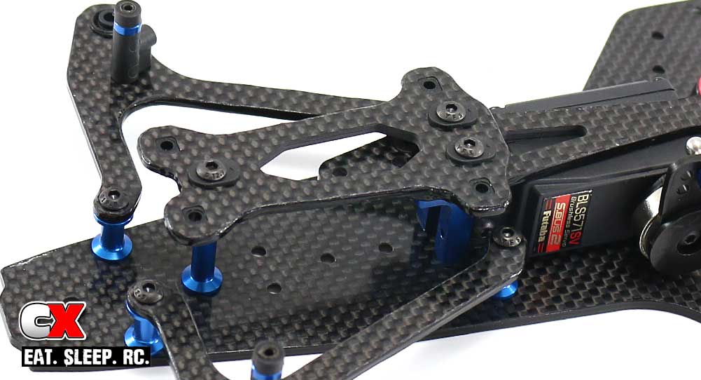
Attach the top plate to the chassis. The screws go through the plastic inserts first so slowly tighten by hand so you don’t strip the plastic.
Step 15:
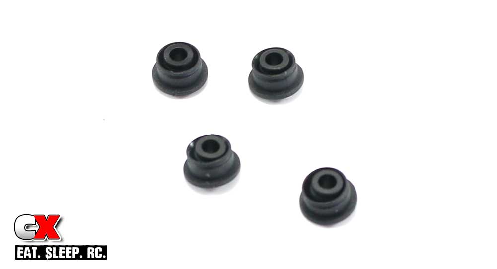
Make 4 more of these inserts using the plastic balls with extended lips on both ends.
Step 16:
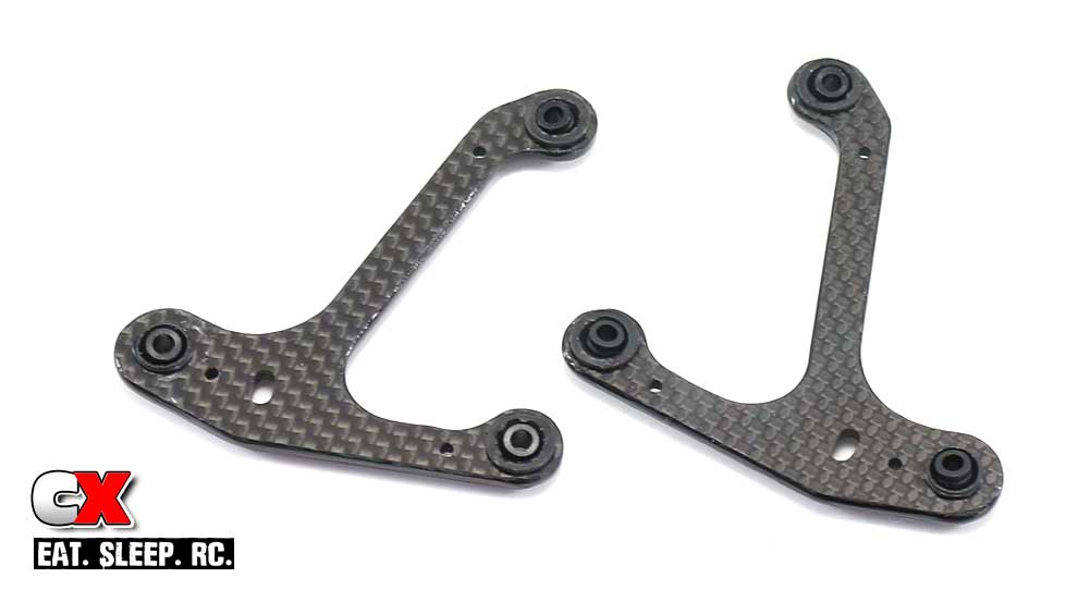
Press them into the graphite upper suspension arms like you did the lower ones.
Note, however, that they are pressed in differently! The 2 on the ‘legs’ press in from the top; the 3rd is pressed in from underneath.
Step 17:
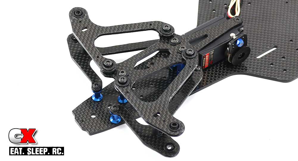
Screw the upper suspension arms in place. The screws go through the plastic inserts so slowly tighten by hand so you don’t strip the plastic.
Step 18:
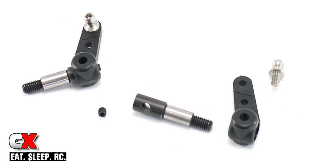
Build a pair of steering arms; insert the setscrew into the axle (only a very short way) and press the axle through the plastic steering arm. Finally, feed the ballstud into the steering arm.
Step 19:
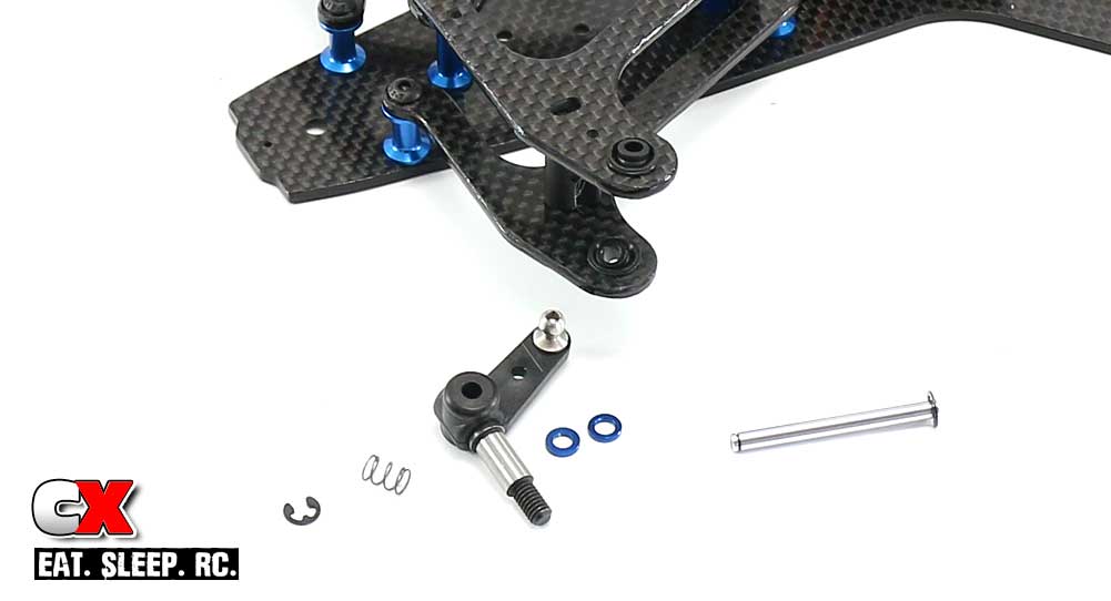
Before we get to the final assembly of the steering, we need to do a little prep work first.
The first thing is to slide the kingpin through the steering arm assembly. The axle and arm holes need to line up perfectly; waiting to do this during final assembly can cause a lot of 4-letter words to exit your head. Prepping it now will help.
Pre-compress the suspension spring a few times with your fingers. Snap an e-clip onto one end of each kingpin.
Ok, start by applying a drop of two of the 10K fluid to the kingpin, using your fingers to spread it around evenly. Now insert the kinpin through the top of the suspension arm, the 2 1mm blue washers, the steering arm assembly and the suspension spring. Capture everything with the lower e-clip.
If the 10K fluid got wiped off, you can apply more at this time.
Step 20:
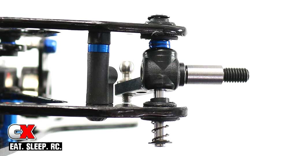
The last step is to set the gap between the bottom of the steering arm and the lower suspension arm. Use the manual to set it properly and lock the steering arm to the kingpin using the setscrew in the back of the axle.
Whew, that was a pretty long step. But, the front end is done and looking good! Let’s get to the bellcrank system.
Team Associated Factory Team F6 Online Build – Part 3
The Team Associated F6 has 3 different steering options; 2 bellcrank setups (long and short) and a forward-servo system. The foward-servo system has been used by a lot of other manufacturers, the bellcrank setup is relatively new. For this build, I’ll be going with the kit setup – the short bellcrank system.
Build Notes:
• None.
Step 1:
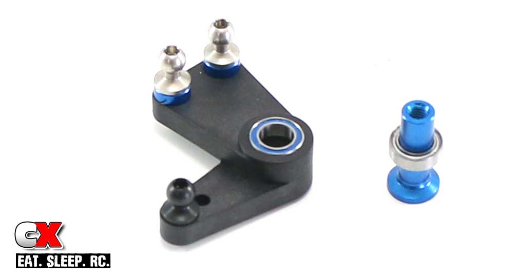
Assemble the bellcrank arm. Press the 5×8 bearings into it as well, blue shield facing out (I’ve shown one in and one on the bellcrank post).
Step 2:
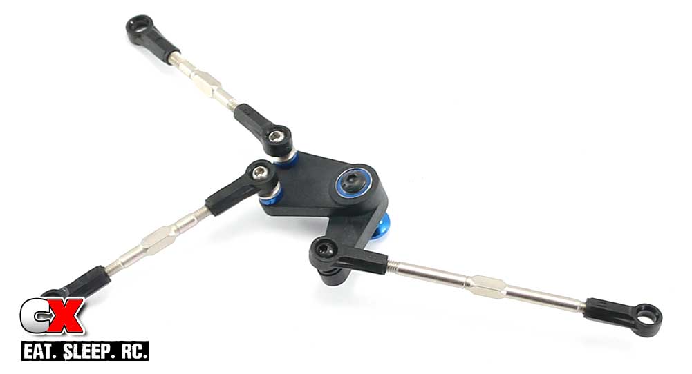
Pop the assembled turnbuckles onto the bellcrank.
Step 3:
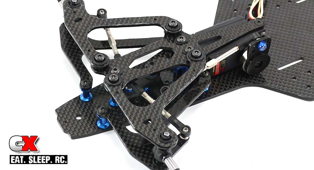
Attach the assembly to the chassis.
Now, that sounds easy but this step will certainly test your patience. I mean really. If it’s making you mental, you can remove the top plate to make it a little easier.
Once you’ve wrestled with that, pop the other ends of the turnbuckles in place.
Short, simple step. Time to move on to the rear suspension!
Team Associated Factory Team F6 Online Build – Part 4
The rear suspension on the Team Associated Factory Team F6 uses a floating pod system. A center shock, links and side dampers control movement through the corners. The center pivot is usually the weak point of the rear pod but, unlike alot of other cars, this one looks to be pretty tough!
Build Notes:
• There are quite a few parts that are directional in this step. I’ll point them out individually but wanted to add this as a heads up in case you don’t read the step notes.
• Steps 13 and 15 show assemblies with screws that appear too long. This is not the case; AE has an interesting way of attaching the center shock using these longer screws. We’ll get to that later.
• Threadlocker is used in Part 4 of the build as well. I’m not going to call it out in every step, but if a screw is going into aluminum, it’s best to add a dab of the blue stuff.
Step 1:
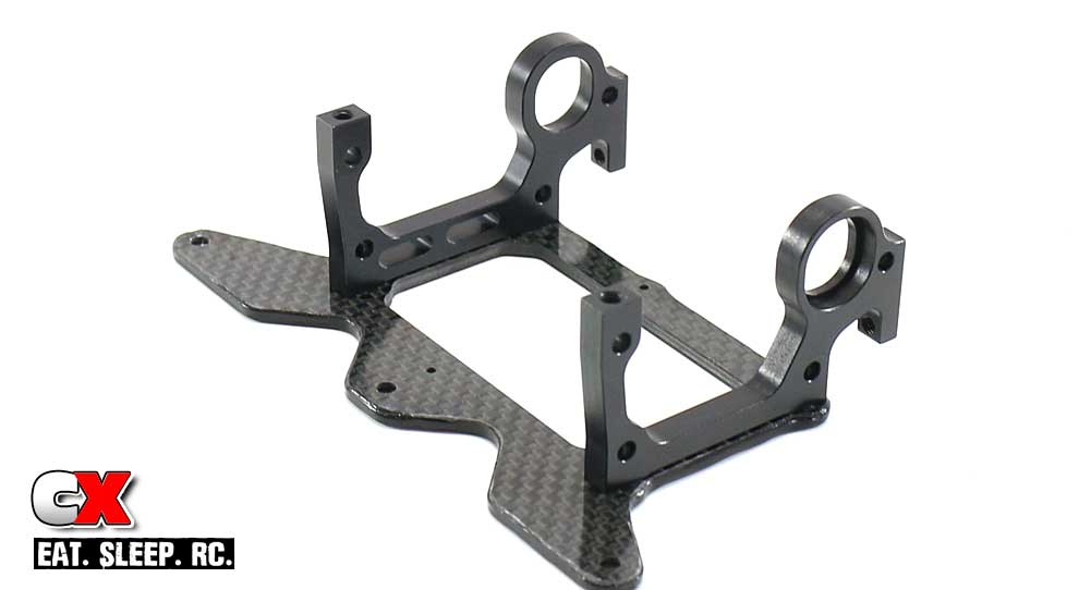
Let’s start this step by attaching the left and right aluminum bulkheads to the lower pod plate. Note the orientation of the rear axle inserts.
Step 2:
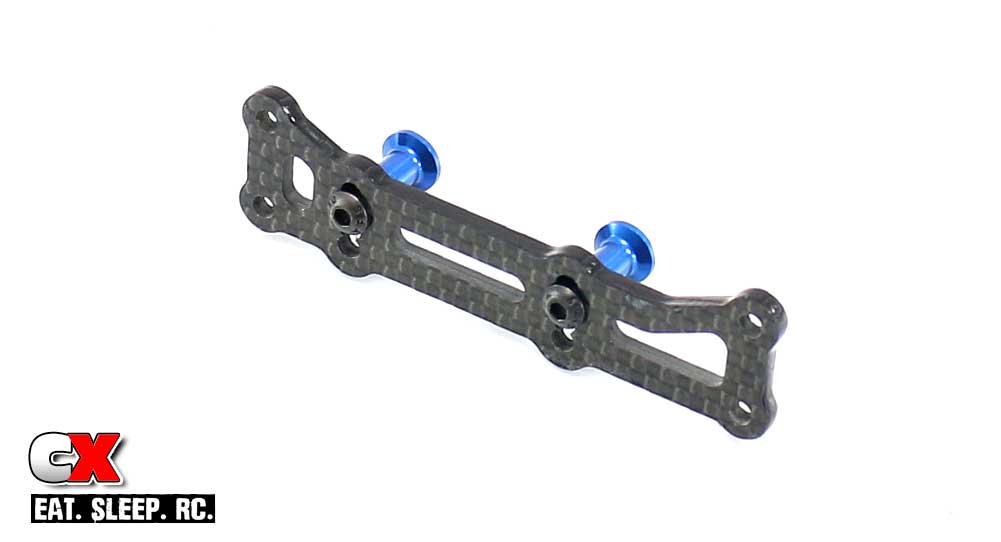
Assemble the rear motor mount brace. This is directional, so make sure the it’s built as shown.
Step 3:
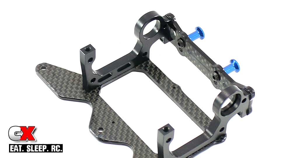
Once built, attach the motor mount brace to the aluminum bulkheads.
Step 4:
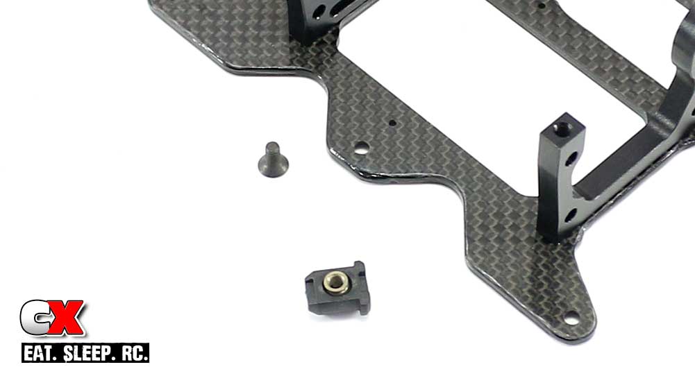
Pop one of the Factory Team pivot balls into the pivot brace slider and attach to the rear pod.
Step 5:
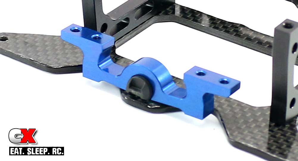
Rotate the slider from Step 4 so that the pivot brace slides on from the front of the pod assembly.
Step 6:
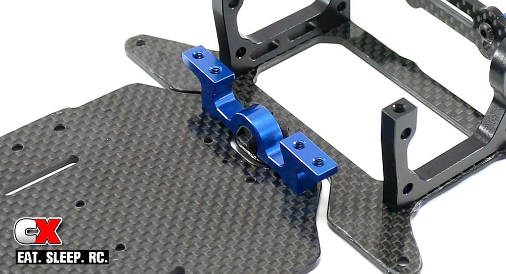
Attach the pivot brace to the main chassis.
Step 7:
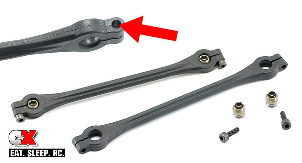
Building the side links is next. Start by popping the Factory Team pivot balls into the pod links.
Now, before inserting the screws, take a look at the holes on each link (see red arrow). One side has a larger hole that the other; the 2x6mm screws goes into this large hole FIRST. Slowly tighten it down until it pinches the FT pivot ball, then back it off slightly. You want it tight but not hindering the movement of the ball. Build 2.
Step 8:
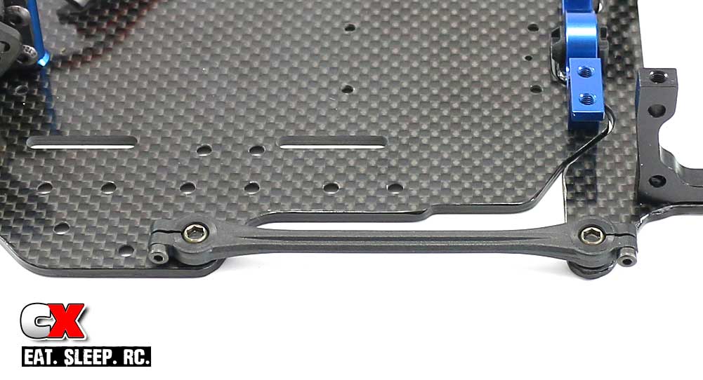
Attach the links to the chassis. Note the orientation of the links based on the 2x6mm screws.
Step 9:
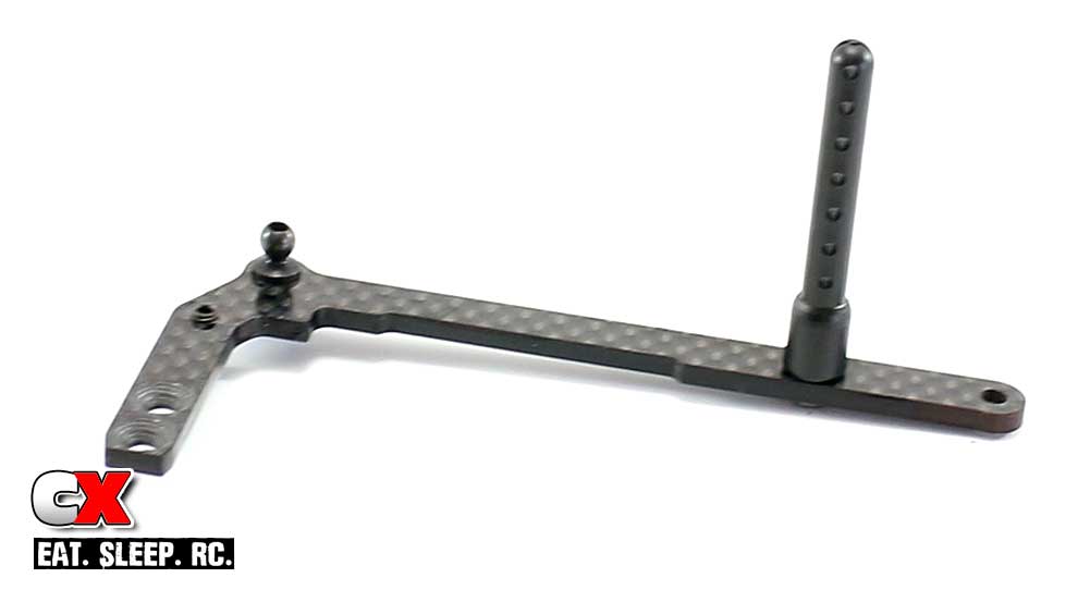
Assemble the left and right chassis braces. Tighten the setscrew until at least 3/4 of it is below the brace.
Step 10:
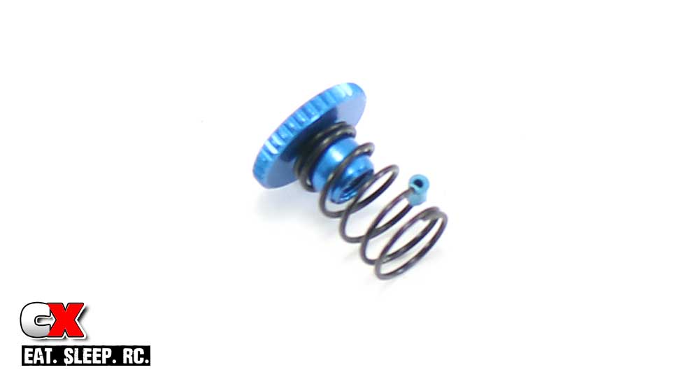
The side spring is designed to ‘pop’ onto the side spring retainer as shown. Make 2 of these.
Step 11:
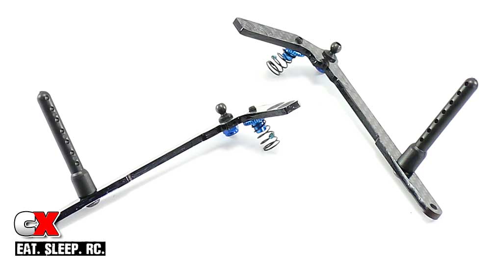
Screw the side spring retainers onto the setscrews. Your final side braces should look like this.
Step 12:
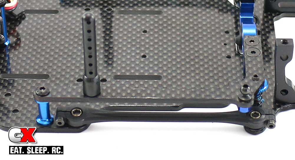
Attach the pair of standoffs to the chassis followed by the chassis braces.
Step 13:
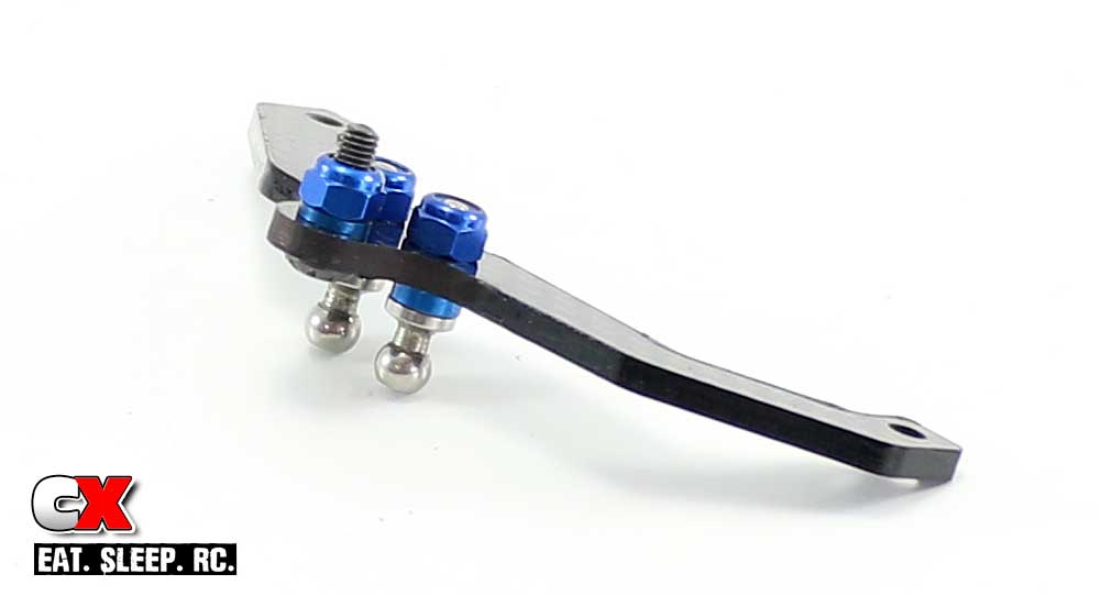
Assemble the rear upper pod plate. Again, don’t worry about how odd the 3x10mm screw looks.
Step 14:
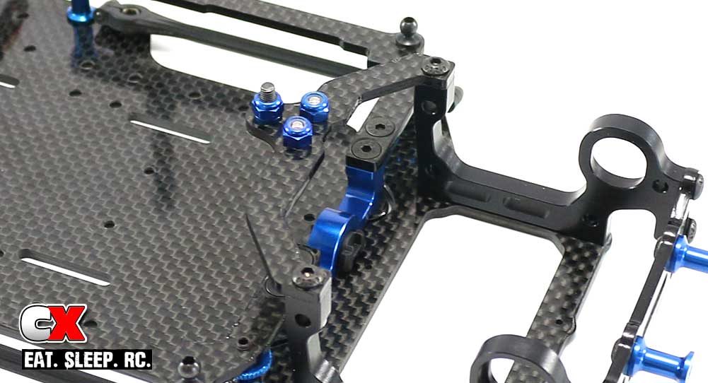
Attach the upper pod plate assembly to the rear bulkheads.
Step 15:
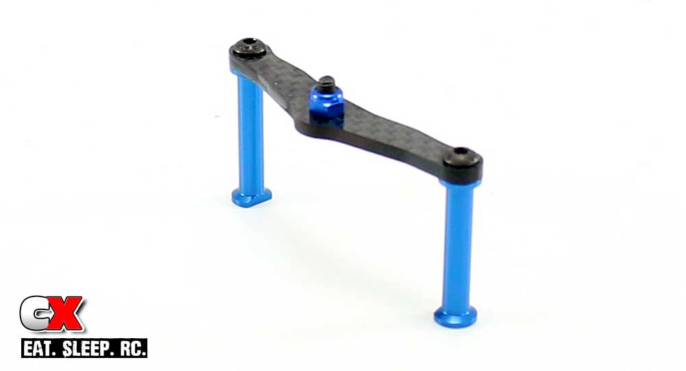
Assemble the shock mount. Note the feet of the standoffs; the flat parts should be facing each other.
Step 16:
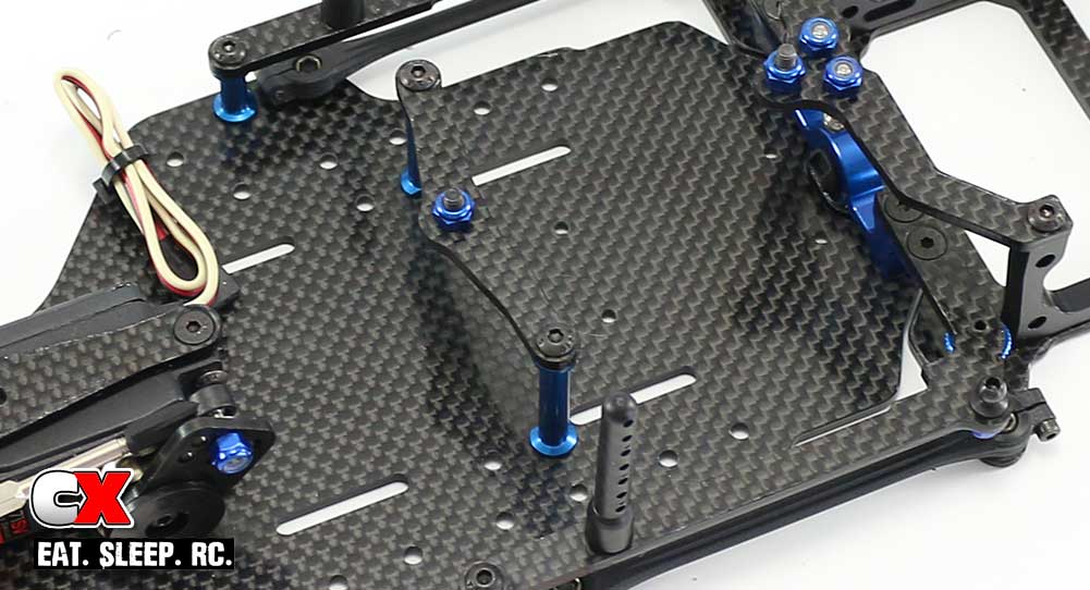
Attach the shock mount assembly to the chassis.
Step 17:
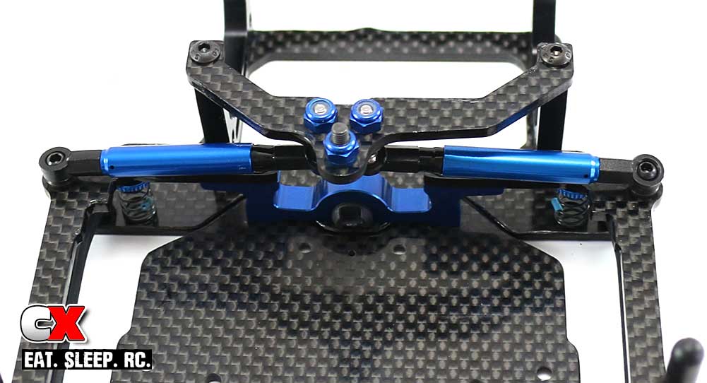
Finally, attach both damper tubes to the mounting locations.
Give the rear suspension a good wiggle; it should feel free with no binding. If you feel some notchiness or binding, head back up to Step 1 and make sure you assembled everything correctly.
On to the rear axle!
Team Associated Factory Team F6 Online Build – Part 5
Team Associated has a strong past when it comes to pan cars, and it shows with all the refinements at the back of the F6. Love the lightened rear hub, super-smooth diff and well-designed motor mount!
Build Notes:
• The differential is the heart of any pan car! Take your time to build it and always make sure it’s maintained to perfection.
Step 1:
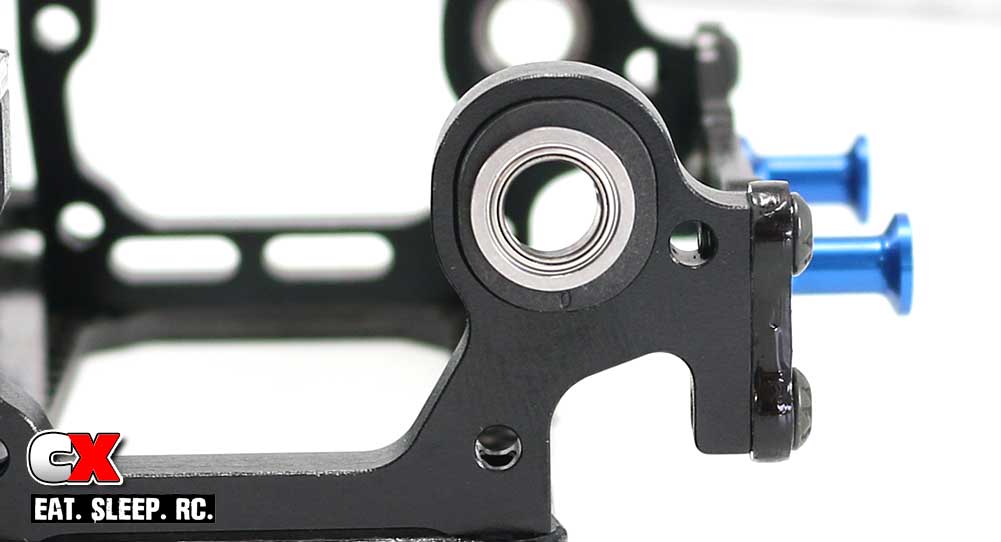
The F6 comes with multiple rear pod inserts to change the ride height and wheelbase of the car. The kit setup states to use the 0-block, so pull 2 of these out and press the flanged bearing into each. Press one assembly into the left bulkhead…
Step 2:
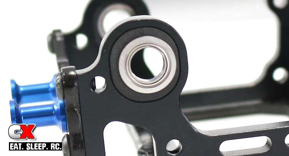
…and the other into the right. Notice the 0 on each; the left one is at the bottom, the right is at the top. You’ll want to match the ride height adjusters like this if you change to a different set later on.
Step 3:
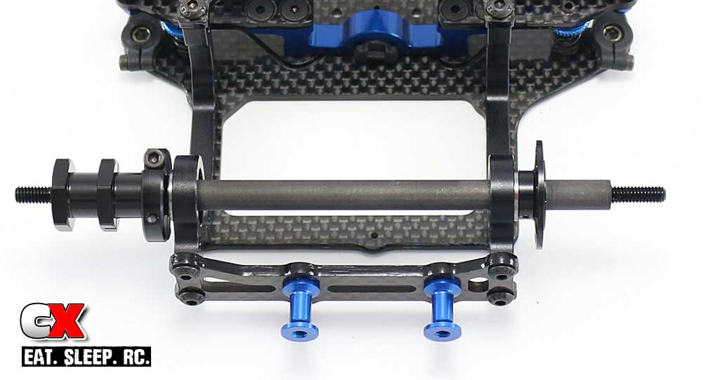
Slide the carbon rear axle through the bearings and secure with the left wheel hub. You’ll want to leave a teeny tiny gap (literally teeny tiny) between the left hub and the bearing; as small a gap as possible before cinching up the hub with the 2.5x12mm screws.
Step 4:
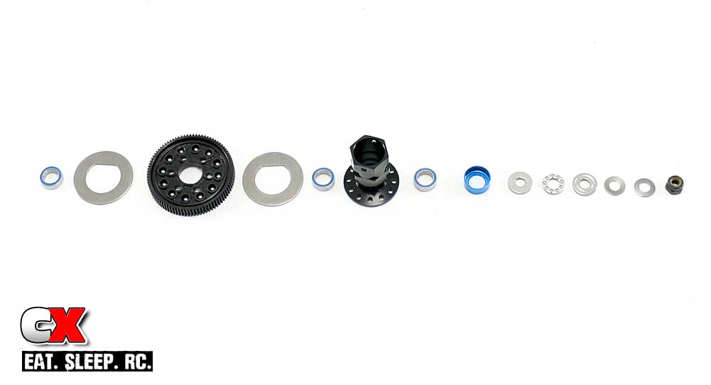
Time for the differential. I’ve laid all the parts out so you can see how they go together. We’ll put them together slowly in the next couple of steps.
Step 5:
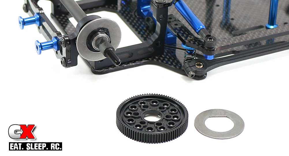
The bearings supplied by AE have a blue shield on one side.
Slide one of the 1/4×1/8″ bearings onto the axle, blue shield facing the car. Apply a small drop of the silicone grease to the hub and set one of the D-Drive rings into place. The grease will help keep the D-Drive ring from moving during assembly.
Press the 12 carbide diff balls into the outer holes of the spur gear.
Step 6:
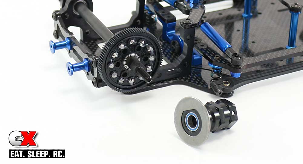
Apply a small amount of silicone grease to the balls on both sides of the spur gear. Slide the spur gear over the bearing.
Press another 1/4×1/8″ bearing into the rear hub, blue shield facing out. Add a small drop of grease to the hub and set the other D-Driver ring into place.
Step 7:
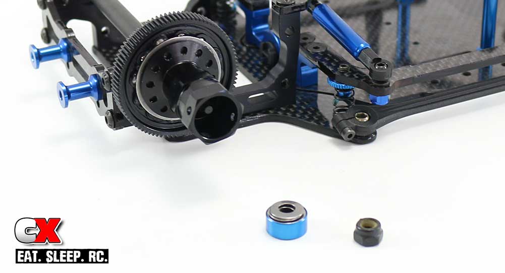
Place the assembled hub onto the axle.
Build the thrust washer setup; thrust washer (with 4.15mm ID hole), bearing and second thrust washer (with 4mm ID hole). Make sure the grooves on both thrust washers are facing the bearing. Add a liberal amount of black grease in-between all the parts. Drop this down into the blue thrust cone.
Add the Bellville washers, making sure the are facing each other (see manual). Carefully slip the final assembly onto the rear axle and secure it all with the M4 locknut.
To set the diff, tighten the M4 locknut down and, while holding both rear hubs, spin the spur gear with your thumb. It you can spin it, tighten the nut down 1/4 turn and try again. Once you get to the point where you can’t spin the spur gear, you should be at a good starting point. You may need to fine tune it slightly during the first run. It’s easier to hold the hubs if you slide the rear tires onto them first.
Step 8:
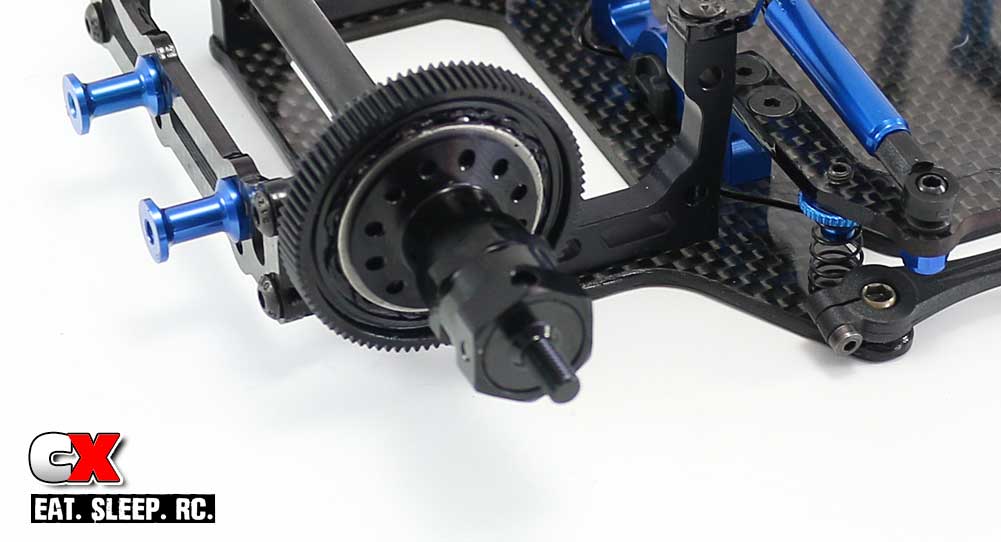
Attach the wheel cap, slide the wheel hub pin through the holes and secure with the setscrew.
Step 9:
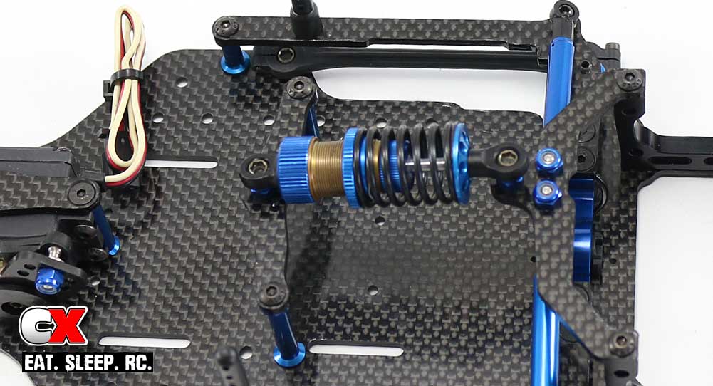
Attach the center shock. The top of the Factory Team pivot balls accepts a 3.0mm driver, making it easy to attach to the shock. This also makes it very easy to disassemble for maintenance as well.
Step 10:
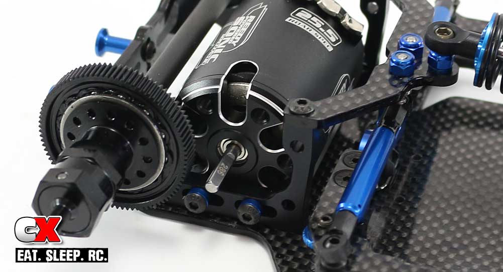
Insert your motor into the chassis and secure with the pair of 3x10mm screws. Don’t forget to add the blue aluminum washers as well.
There you have it; a built and ready-to-rock rear axle! We didn’t include a pinion gear yet as I’m not 100% sure what my gearing is going to be, so I’ll be adding that later.
Next up – adding the front and rear wings!
Team Associated Factory Team F6 Online Build – Part 6
One of the cool parts of the Team Associated F6 is the fact that it comes with its own set of front and rear wings; no using other companies wings to complete the car. On top of that, they’re great looking, adjustable wings!
Build Notes:
• Team Associated gave me one of their blinking brake lights to add to the build. This light fits into a hole at the base of the rear wing with a long lead that plugs into the receiver. I will be installing it at this time.
Step 1:
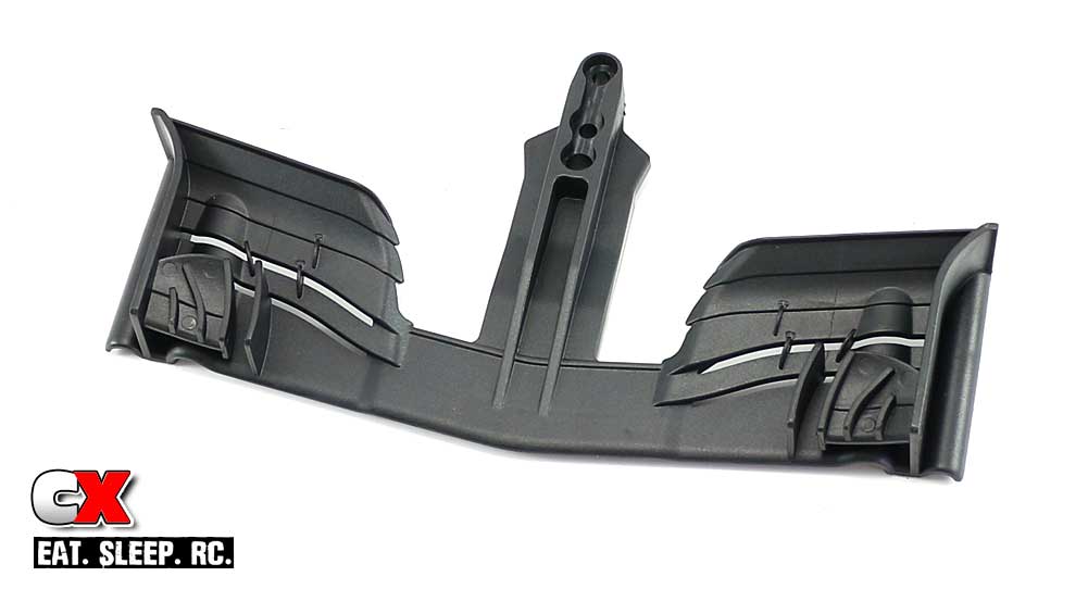
The front wing comes in 3 pieces; attach the 2 inner winglets as shown.
Step 2:
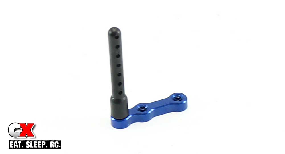
Attach the front body mount to the aluminum wing plate.
Step 3:
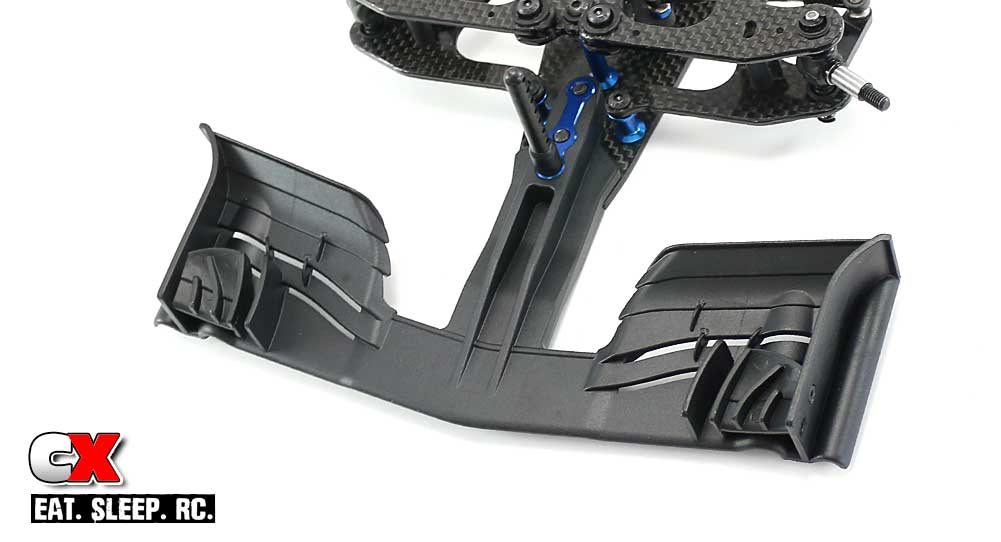
Press the front wing plate into the recess in the wing and attach using the pair of 4x14mm screws. This is a nice, strong mounting system!
Step 4:
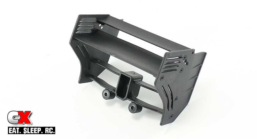
Assemble the rear wing. I’m using the kit mounting locations.
I found it easiest to attach all the cross parts to one side of the wing (leaving the screws slightly less-than snug), then attach the second side of the wing. Tighten up all the screws.
Step 5:
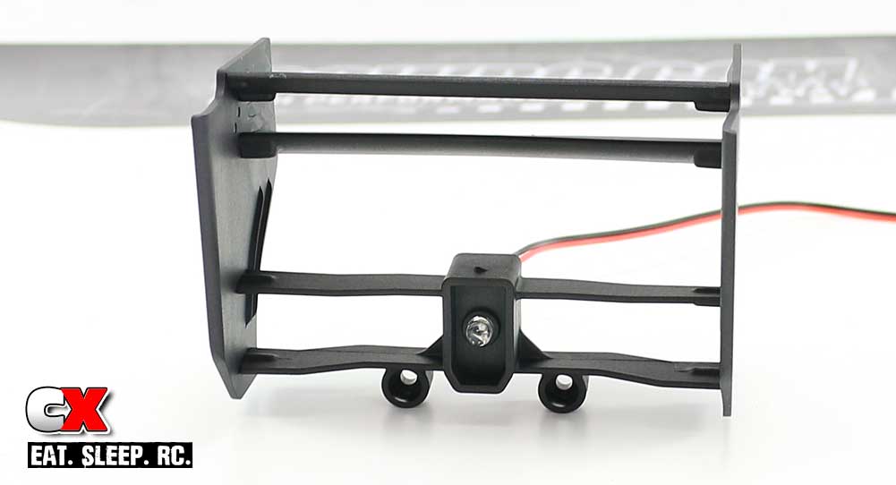
Optional step; this is a quick shot of the blinking brake light installed in the rear wing. I used a dab of Shoo Goo to keep it in place.
Step 6:
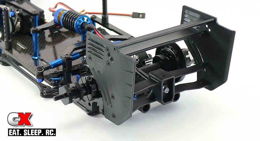
Attach the rear wing assembly to the aluminum stand offs.
Wah lah. Wings attached and looking great!!!
Moving on to the final step – the electronics!
Team Associated Factory Team F6 Online Build – Part 6
One of the cool parts of the Team Associated F6 is the fact that it comes with its own set of front and rear wings; no using other companies wings to complete the car. On top of that, they’re great looking, adjustable wings!
Build Notes:
• Team Associated gave me one of their blinking brake lights to add to the build. This light fits into a hole at the base of the rear wing with a long lead that plugs into the receiver. I will be installing it at this time.
Step 1:
The front wing comes in 3 pieces; attach the 2 inner winglets as shown.
Step 2:
Attach the front body mount to the aluminum wing plate.
Step 3:
Press the front wing plate into the recess in the wing and attach using the pair of 4x14mm screws. This is a nice, strong mounting system!
Step 4:
Assemble the rear wing. I’m using the kit mounting locations.
I found it easiest to attach all the cross parts to one side of the wing (leaving the screws slightly less-than snug), then attach the second side of the wing. Tighten up all the screws.
Step 5:
Optional step; this is a quick shot of the blinking brake light installed in the rear wing. I used a dab of Shoo Goo to keep it in place.
Step 6:
Attach the rear wing assembly to the aluminum stand offs.
Wah lah. Wings attached and looking great!!!
Moving on to the final step – the electronics!

