
Team C TM4 Online Build
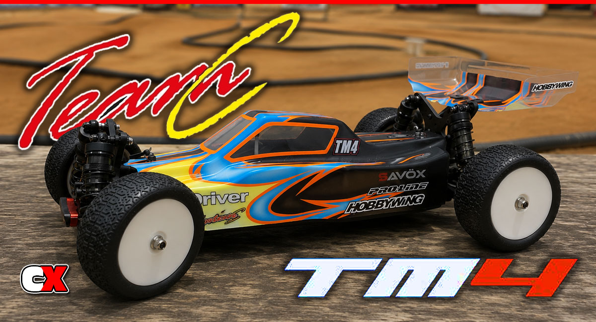
When you think of 1:10 scale 4WD buggies, your mind probably heads right for big dogs like Team Associated, TLR, Kyosho and maybe even XRay. Team C may not be a household name, but their 4WD buggy, the TM4, is putting down some hot laps and having those other guys take notice.
We’ve got our hands on the TM4 for a build and I have to say I’m really liking this car! Parts quality is excellent and aside from a few minor build issues, this buggy went together well.
Following is our step-by-step build, explaining the standard steps as well as keying in on some of the areas to pay a little more attention too.
Team C TM4 Online Build – Part 1
The first part of our Team C TM4 build has us prepping the main deck. This is a very easy, 3-step process so you should just breeze through it before heading on to the differentials.
Build Notes:
• In this step we’ll be attaching aluminum center bulkheads to the chassis. You will need to get yourself some blue threadlocker to help lock the screws in place. There will be other uses for the threadlocker during the build, so use only a very small drop on each screw to help keep it in place.
Step 1
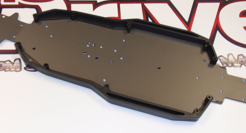
The first step in prepping the chassis is to attach the chassis side rails.
Step 2
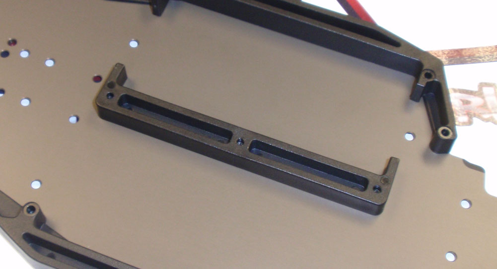
Next, attach the ‘central reinforcing bar’, otherwise known as the battery cage. Note the direction it is facing.
Step 3
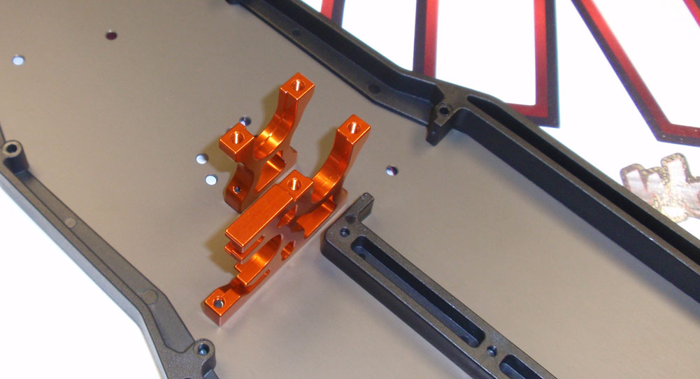
Finally, attach the two, aluminum center bulkheads. Note the direction they are facing. It is important that you pay attention to the bearing support ribs to make sure they are facing each other. A dab of threadlocker on the screws will help keep them secure.
Like I said, really easy. Time to move on to the differentials.
Team C TM4 Online Build – Part 2
Team C’s TM4 comes with a great set of fluid-filled gear diffs. Assembly is pretty easy and I haven’t had any troubles with them leaking; both major plusses when it comes to diffs.
Build Notes:
• Make sure you’re working on a clean surface that is covered with a towel or work mat. You will be dealing with diff fluids and, no matter how hard you try, you will spill some. Just be prepared with clean-up items.
Step 1
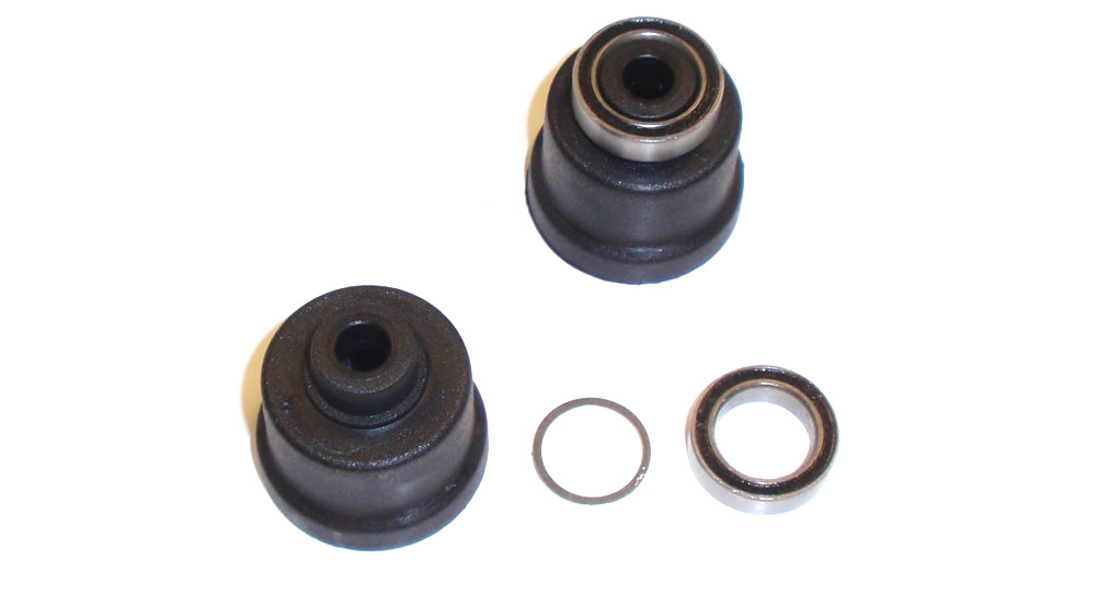
Slide a 10×12 washer and bearing onto each diff housing. Press the bearing down to completely seat it.
Step 2
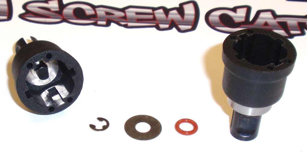
Insert the outdrive into the diff housing. While standing the assembly up, slide the red o-ring followed by the 5.1×13 washer onto the outdrive. Drop the e-clip into the diff housing and position it to snap into the groove on the outdrive. This could be a little tricky; a set of needlenose pliers will help snap the e-clip into place.
Step 3
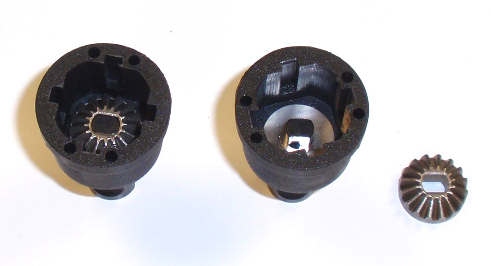
With the diff housing still standing, position and drop the 16t sungear into place. It will key to the outdrive; push it down until it sits flush with the outdrive.
Step 4
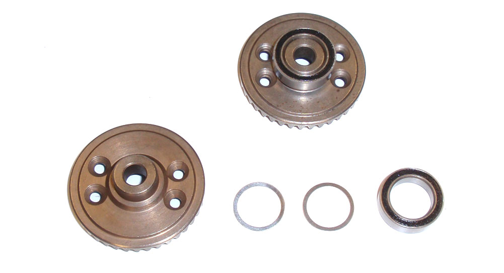
Slide two 10×12 washers and a bearing onto each diff gear. Press the bearing down to completely seat it.
Step 5
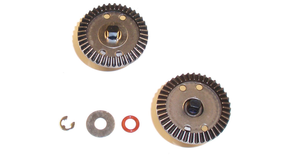
Insert the outdrive into the diff gear. While standing the assembly up, slide the red o-ring followed by the 5.1×13 washer onto the outdrive. Drop the e-clip onto the diff gear and position it to snap into the groove on the outdrive. Again, this could be a little tricky, so use your needlenose pliers to snap the e-clip into place.
Step 6
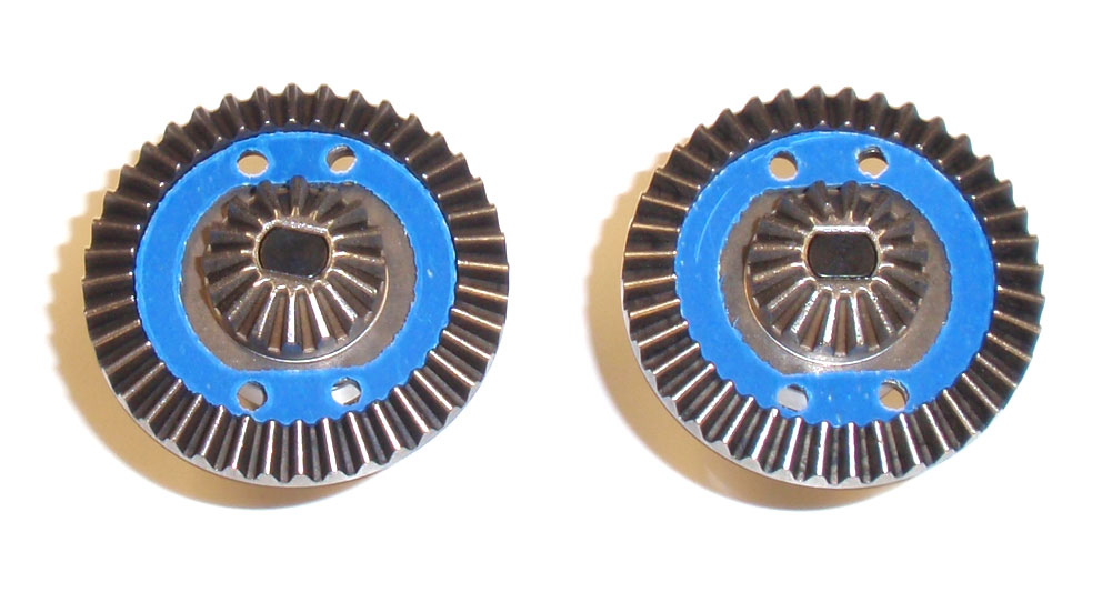
Drop and key a 16t sungear to the outdrive. Press it down to make sure it sits flush with the top of the outdrive. Take a diff gasket and set it in place, lining up the holes in the gasket and gear.
Step 7
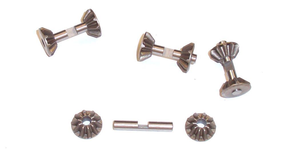
Build 4 sungear assemblies. A little drop of grease will help keep the gears from sliding around. Note the flat spots on the shafts.
Step 8
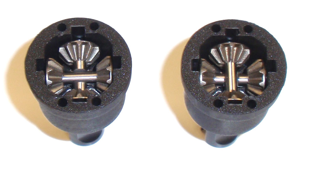
Drop one sungear assemblies into the grooves of the diff housing, making sure the flat spot on the shaft is facing up. Drop a second sungear assembly into the grooves of the diff housing, making sure the flat spot on the shaft is facing down.
Step 9
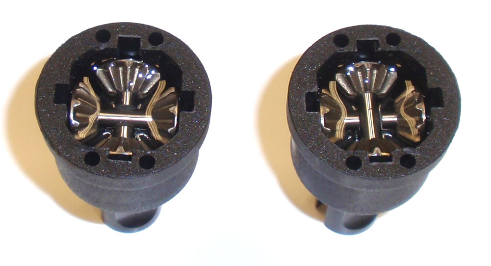
Fill each diff up with diff fluid, just to the top of the sungears. The manual suggests a starting setup of 5000wt diff fluid up front, 2000wt diff fluid in the rear. It also highlights what to use if you are running on a low grip or high grip track.
Step 10
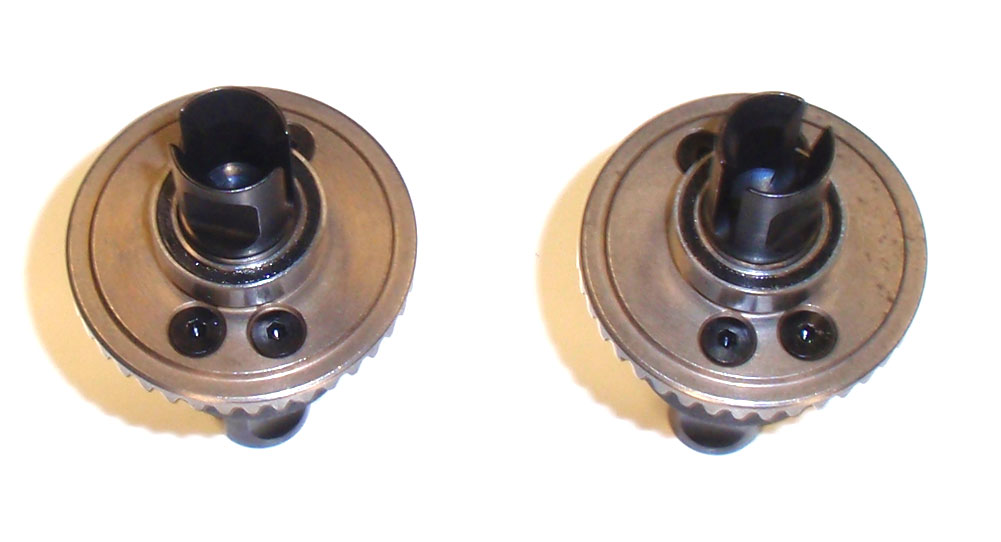
Slowly flip the diff gear assembly over and mate it to the diff housing, lining up the screw holes in the gear and housing. Press it together and rotate the diff outdrive to make sure the gears are meshing correctly. Screw together slowly and clean up any excess diff fluid.
Step 11
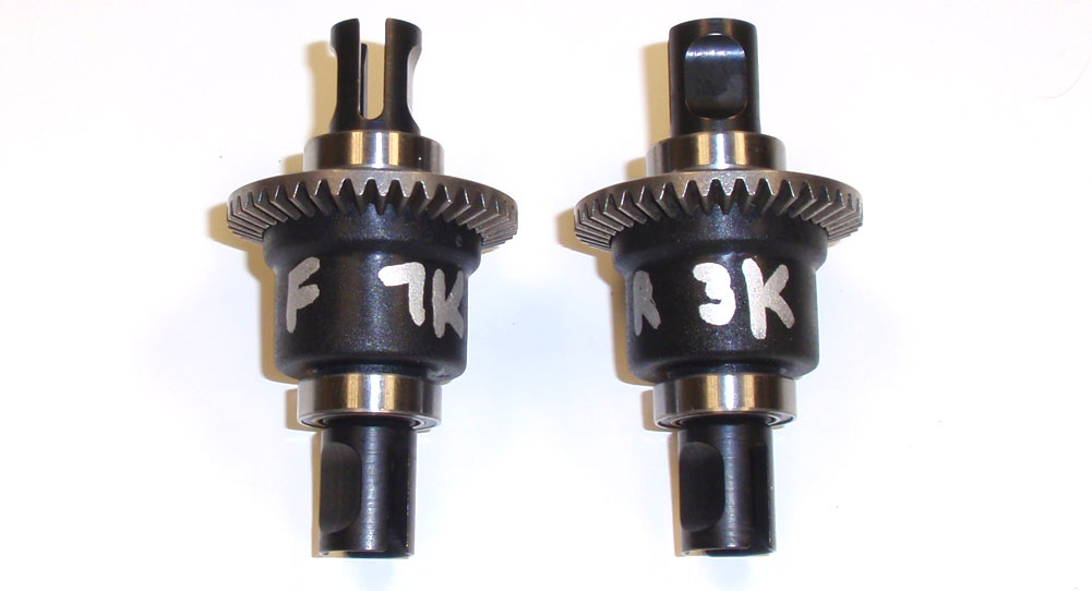
I like to write my fluids on the housings with a silver Sharpie so I know which is the front/rear and what fluid is in them.
As a final note, rotate each diff to make sure it moves smoothly. Give them one more good cleaning and set them aside. Good job.
Team C TM4 Online Build – Part 3
Diffs are built so it’s time to install them in the gearboxes and get the gearboxes attached to the chassis.
Build Notes:
• This build step is pretty easy, just pay attention to which gearbox and center drive axle you use. The gearboxes have different output angles while the drive axles are different lengths. I’ll explain it better in each step.
• A shart eye will notice that the differential build ended with Step 14 and that this part of the build is starting with Step 14. Oops on my part. Too much work to relabel all the pix so we’re starting off with Step 14. Deal with it.
Step 1
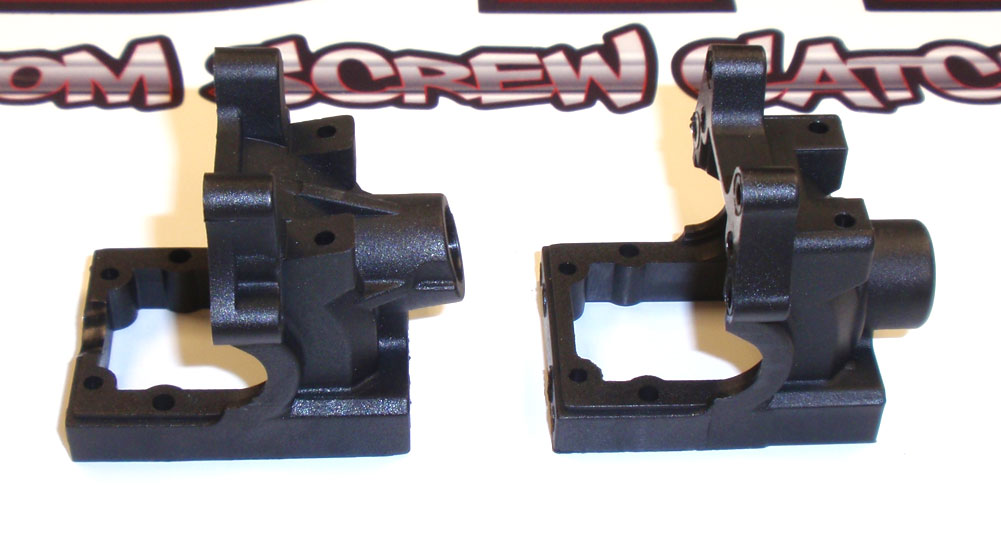
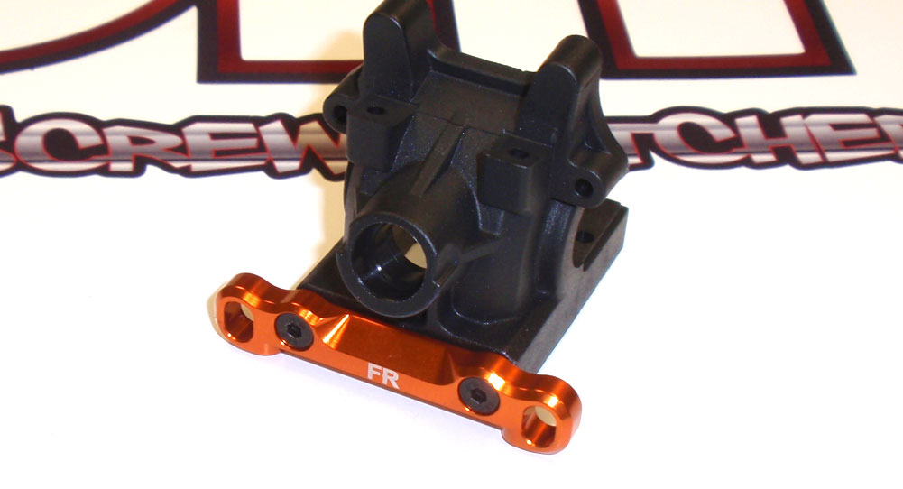
Let’s first get aquainted with the two different gearboxes. The one on the left is the front box; notice the angled output opening. This angle takes into consideration the kickup built into the front of the TM4; the axle is straight once it is installed. The gearbox on the right is the rear box. We’ll be building the front gearbox first.
Step 2
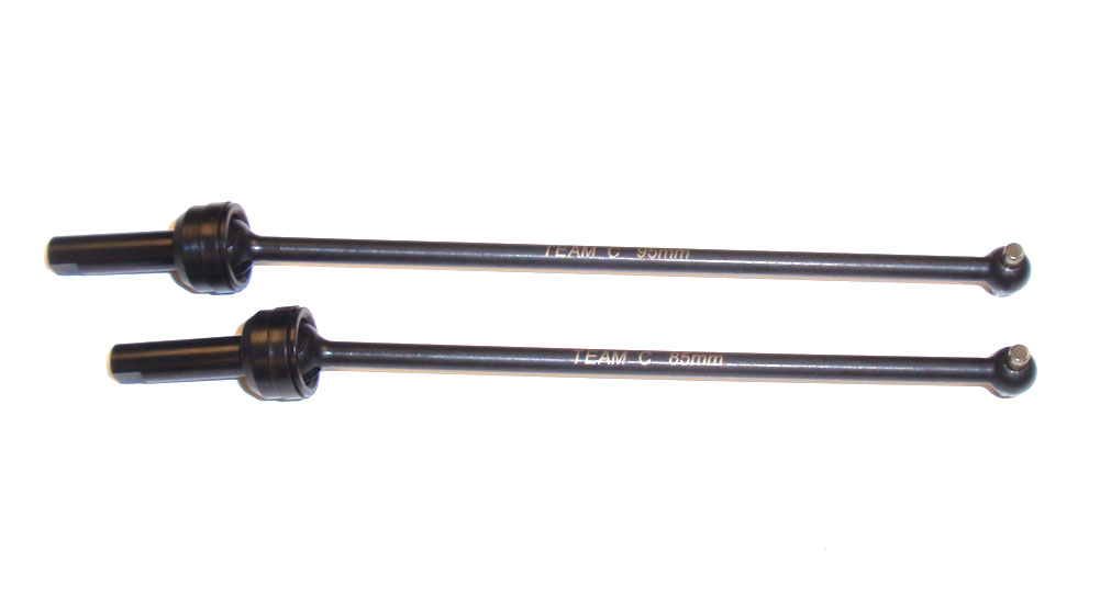
Now assemble your center drive axles. You’ll see the shafts come in two lengths: an 95mm shaft (the rear shaft; the one on top) and an 85mm shaft (the front shaft; the one on the bottom). Grab the 85mm shaft since we’re working on the front of the TM4. If you get confused, the lengths are printed right on them.
Step 3
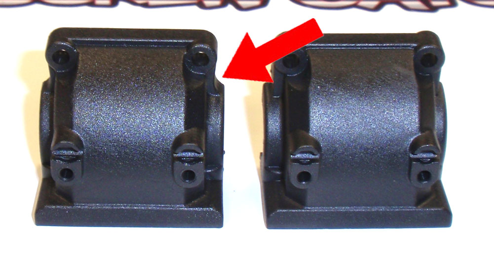
We also have to take a quick look at the gearbox covers; the front and rear ones differ as well. The red arrow points to the different clearance area the front cover has that the rear one does not need. Grab the front cover (the one on the left) and keep it handy for the front gearbox build.
Step 4
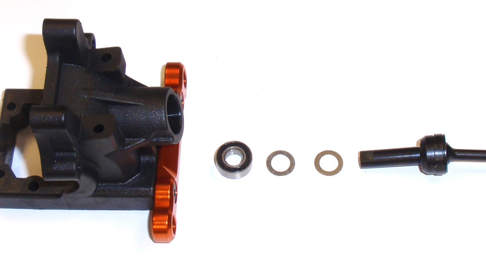
Attach the FR arm mount to the front gearbox as shown. ‘FR’ stands for ‘F’ront of the car, ‘R’ear mount (or inner mount).
Step 5
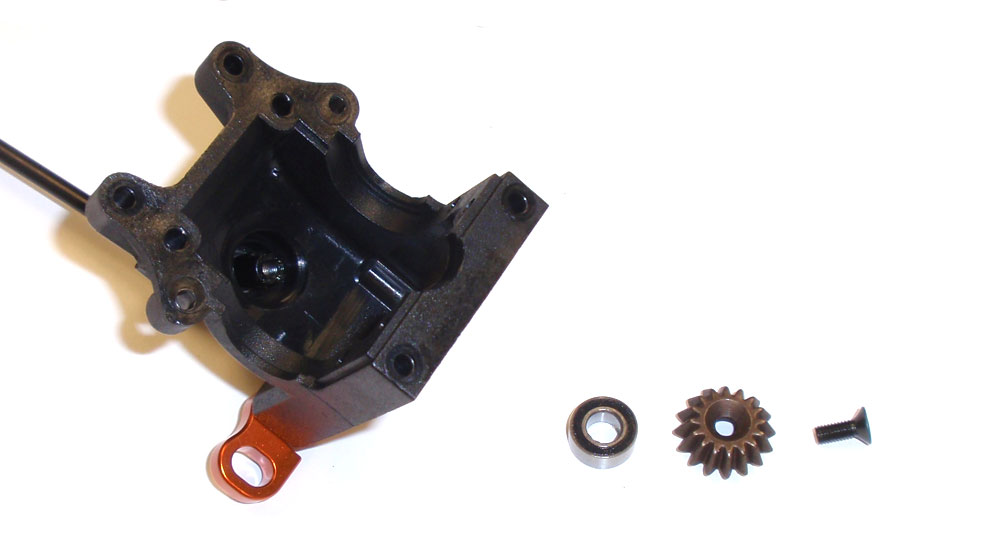
Slide two 5×8 washers onto the front drive axle followed by a 5×10 bearing. Once seated, slide the assembly into the gearbox opening.
Step 6
Holding the axle in place, slide another 5×10 bearing onto the shaft followed by a 16t sungear. The gear should slide all the way onto the axle; secure with the M3x8 screw. A dab of threadlocker here is suggested.
Step 7
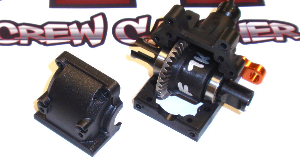
Slide your front diff assembly into the gearbox as shown, pressing it in to make sure the bearings set into place. The diff NEEDS to be assembled in this direction. Now slide the front gearbox cover into place and screw together.
Step 8
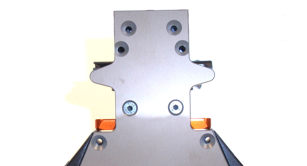
Fit the front gearbox to the chassis and secure. The orange FR arm mount might make positioning it a little difficult so just take your time.
Step 9
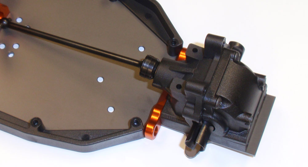
Here is what your front gearbox should look like installed.
Step 10
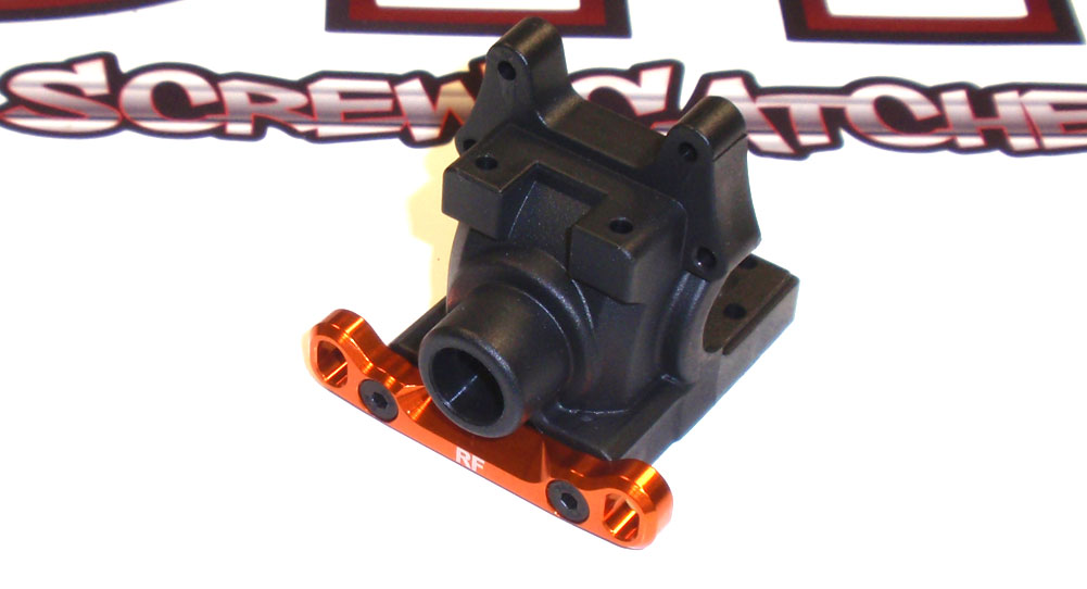
We’ll do basically the same thing with the rear gearbox install. Attach the RF arm mount to the rear gearbox. ‘RF’ stands for ‘R’ear of the car, ‘F’ront mount (or inner mount). Yes, it seems oddly backward from the front but once it’s assembled you’ll understand it.
Step 11
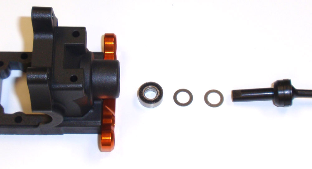
Using your 95mm center axle, slide two 5×8 washers and a 5×10 bearing onto it. Press this assembly into the rear gearbox.
Step 12
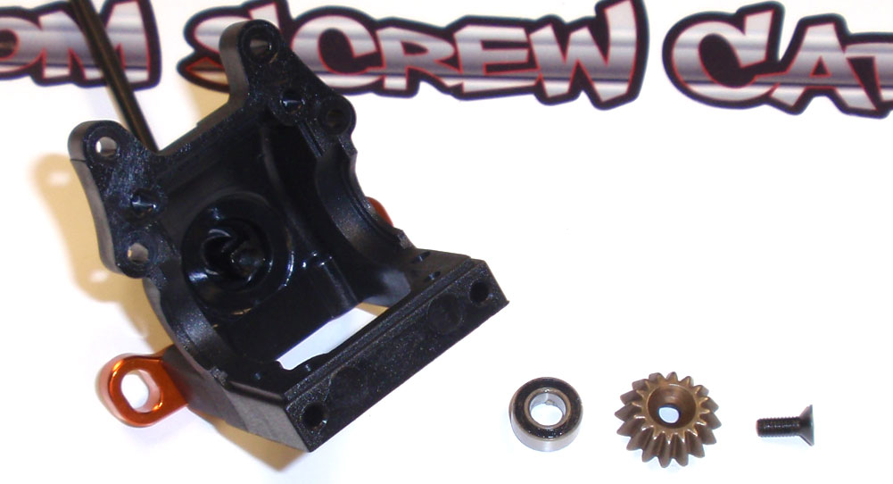
Holding the axle in place, slide another 5×10 bearing onto the shaft followed by a 16t sungear. The gear should slide all the way onto the axle; secure with the M3x8 screw. A dab of threadlocker here is suggested.
Step 13
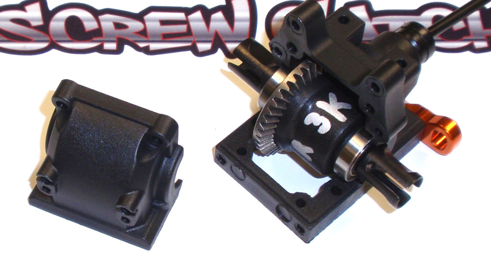
Slide your rear diff assembly into the gearbox as shown, pressing it in to make sure the bearings set into place. The diff NEEDS to be assembled in this direction. Now slide the rear gearbox cover into place and screw together.
Step 14
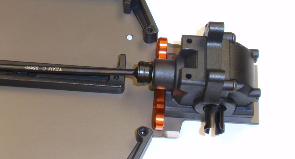
Set the gearbox assembly onto the chassis and secure.
You can grab the center axles and rotate them to make sure everything feels free. Another step down, another step closer.
Team C TM4 Online Build – Part 4
To help spare the drivetrain from sudden jolts, an adjustable center slipper clutch is included with the TM4. It’s similar in design to most 4WD center slippers and does a good job of keeping things in check when the surface gets slippery.
Build Notes:
• The only thing you will want to watch out for is starting Step 28; The Slipper Hub Set-A needs to have the flat side facing the gear. Other than that, this is a pretty easy step.
Step 1
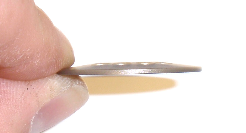
As I mentioned in the Build Notes, you’ll see that the Slipper Hub Set-A has a flat side and a humped side. Just make sure the flat side faces the spur gear in the next step.
Step 2
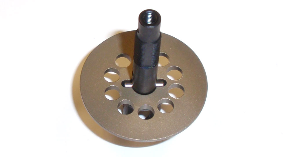
Slide the longer, 2×9 pin through the slipper shaft followed by the slipper hub.
Step 3
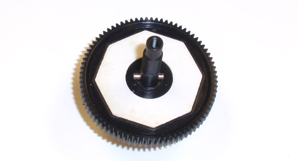
Position the slipper pads against the spur gear and slide this assembly into place on the shaft. If the pads don’t stay in place, you can add a drop of grease to help secure them. Slide the shorter, 2×7 pin through into place as shown.
Step 4
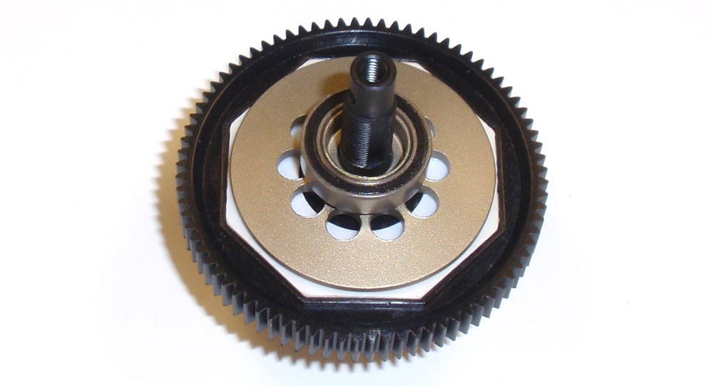
Take Slipper Hub Set-B and set it into place on the slipper shaft. Press a 10×15 bearing onto it. If it’s a little tight, try press the bearing on before setting the hub in place.
Step 5
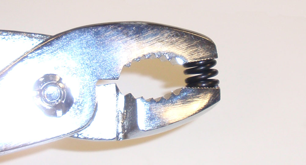
Pre-compress the slipper spring. This will get it a ‘set’ prior to installation.
Step 6
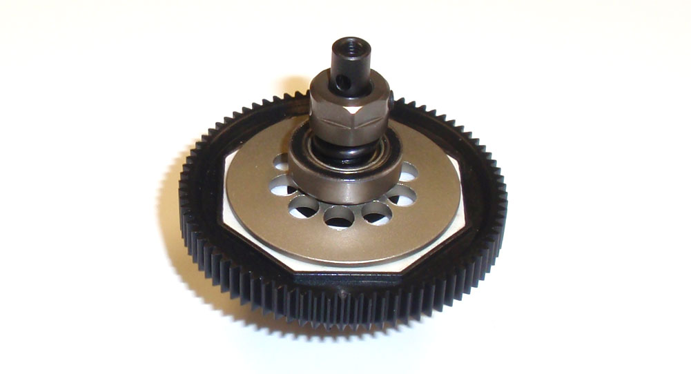
Drop the spring over the slipper shaft. Take the slipper nut and screw it onto the slipper shaft. Using calipers (or if you’re really good, you can eyeball it), screw the nut down until there is about a 3.5mm gap between it and the bearing. Once in place, secure with the M3x3 setscrew. This is a starting setting and may need to be adjusted during or after the first run.
Step 7
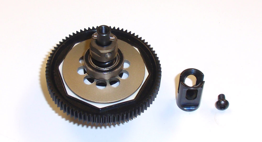
Slide the other 2×7 pin through the hole in the slipper shaft and slide the outdrive cup into place. Secure with the M3x5 screw. A dab of threadlocker here is also suggested.
Step 8
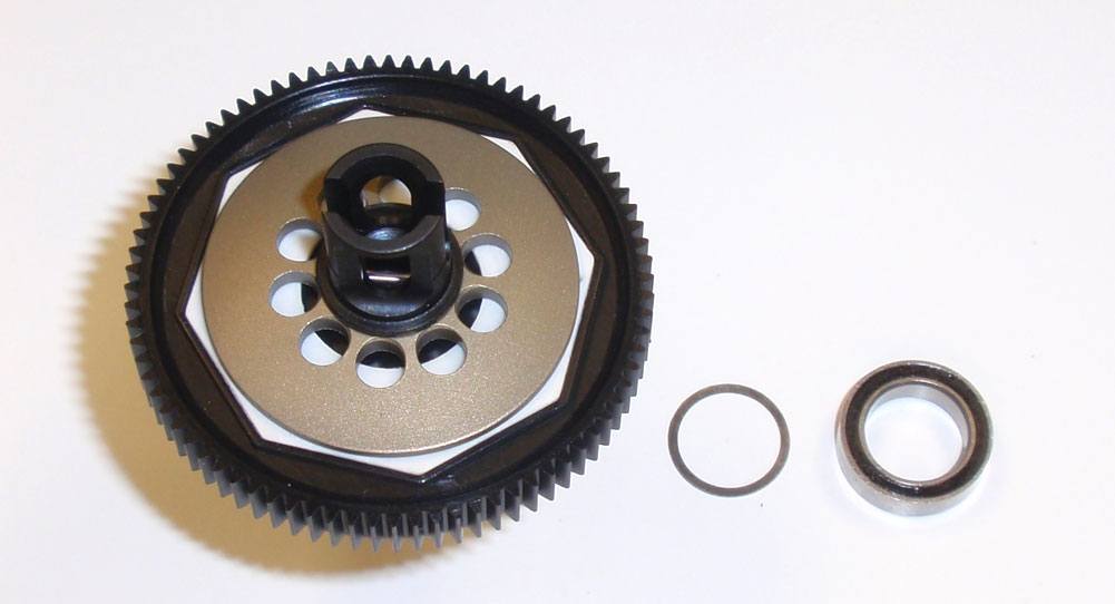
Flip the slipper clutch over and and slide a 10×12 washer and 10×15 bearing over the outdrive cup. Make sure both 10×15 bearings are completely seated.
Step 9
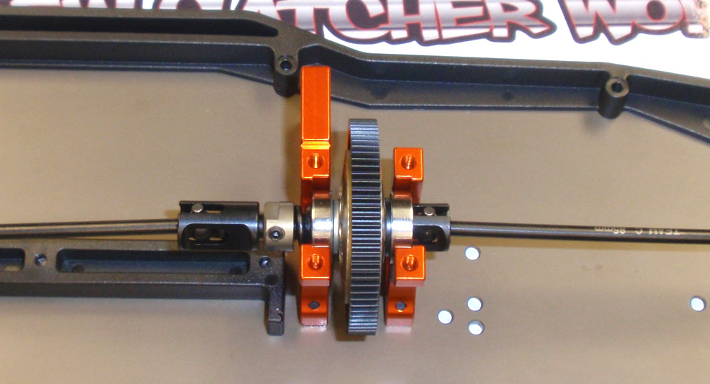
Grab your chassis and install the slipper clutch, making sure you key the drive bones to the outdrives. The longer side (with the slipper nut) faces the rear of the TM4, the shorter faces the front.
There ya go … slipper clutch installed. Set this aside as we start working on the next step.
Team C TM4 Online Build – Part 5
In Part 5 of our Team C TM4 build, we install the servo, servo saver and complete steering rack. We also get to build ONE turnbuckle.
Build Notes:
• You may want to hook up your electronics to make sure your servo is centered prior to installation. The TM4 positions the servo with the horn facing out, so even if it isn’t centered, fixing it at the end of the build is no big deal.
• During the servo saver build portion, I suggest using a little bit of black grease inbetween the saver arms. This helps prevent any dirt or grime from sneaking in there and causing any binding. I’ve noted this in the actual step as well.
Step 1
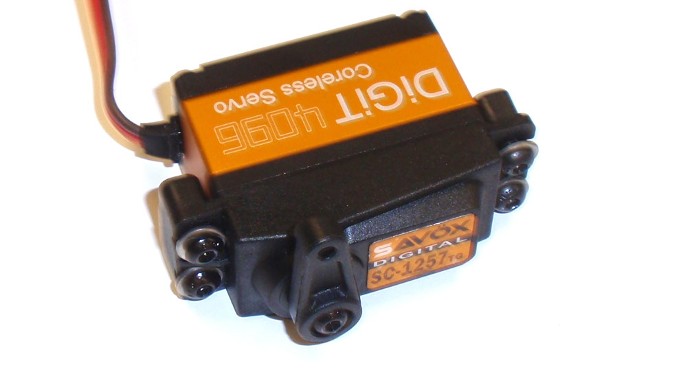
Let’s start by attaching the servo arm and mounts to whatever servo you’ll be using. Don’t tighten down the screws in the mounts all the way just yet. In my TM4, I’m dropping in a Savox SC-1257TG servo.
Step 2
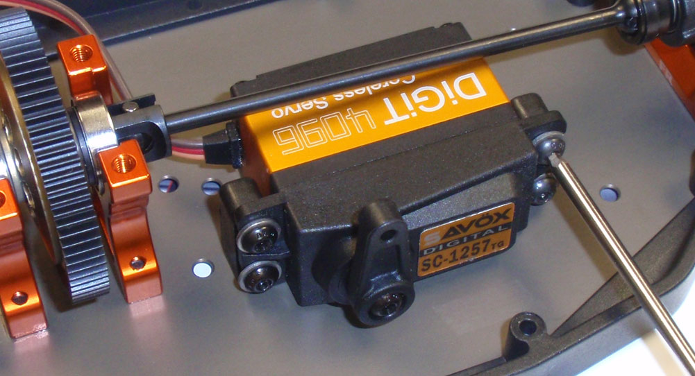
Slide the servo assembly into position and attach with the two M3x8 screws. You can now tighten down the servo mount screws.
Step 3
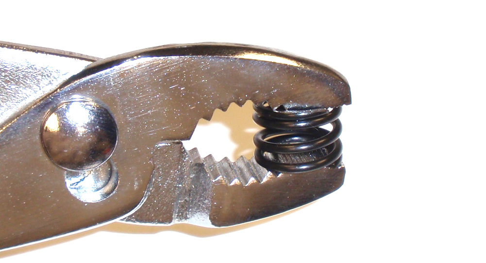
Pre-compress the servo saver spring. One or two full compressions should be good.
Step 4
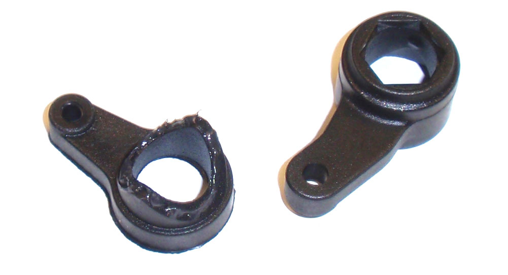
Grab your servo saver arms and, as mentioned in the build notes, apply a little black grease to them as shown.
Step 5
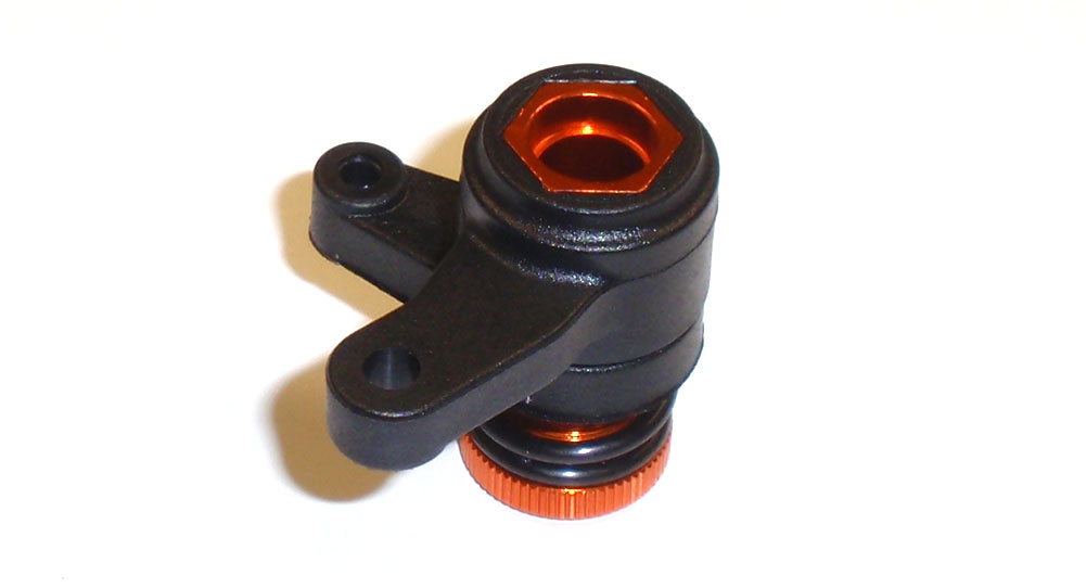
Now assemble the servo saver per the manual. Screw the servo saver adjustment nut up so that there is a 8mm gap between the nut and the bottom of the lower servo saver arm. Since most manufacturers measure on the side of saftely, I’ve found that most high-end servos are strong enough to go without servo savers. Because of this, I like to adjust my servo saver to make it flex a little less, so I set mine at about 6mm. Please do this only if you’re using a good, high-quality racing servo. Anything other than that could result is broken gears inside your servo.
Step 6
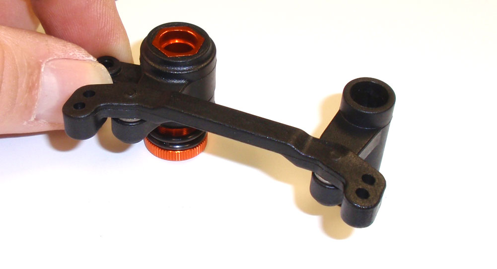
Connect the servo saver assembly and left-side servo arm to the steering rack. Do not overtighten the M3 screws; tighten just enough to allow free movement of the rack.
Step 7
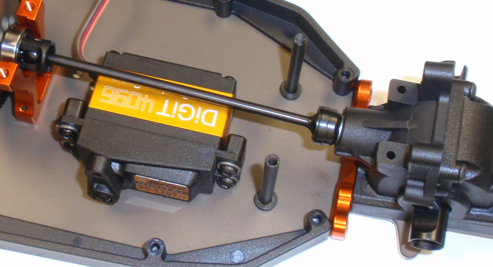
Install the pair of steering posts to the chassis. A drop of threadlocker on the M3x8 screws is suggested.
Step 8
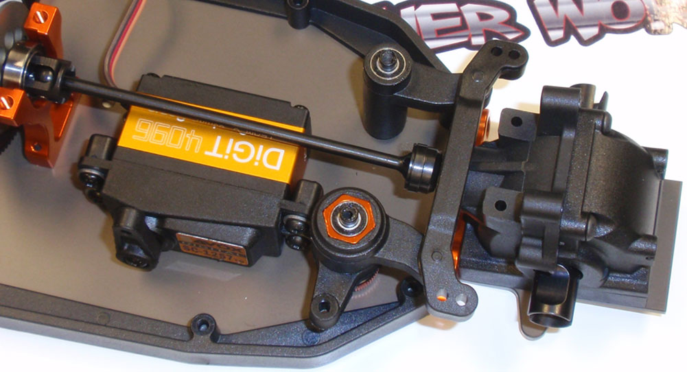
Press the 4×8 bearings into the top and bottom of both steering arms and slide the assembly onto the steering posts. It can be a little tricky, so make sure the arms and being lowered onto the posts at exactly the same time. Check that there is free movement in the rack. We are not installing the two orange, 4×6 spacers quite yet. This prevents them from getting lost in case we pick up the car for any reason. We’ll do this once we’re ready to install the top deck.
Step 9
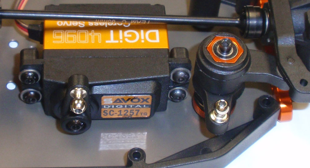
Install a long ball stud into the steering arm and a short ballstud into the servo arm.
Step 10
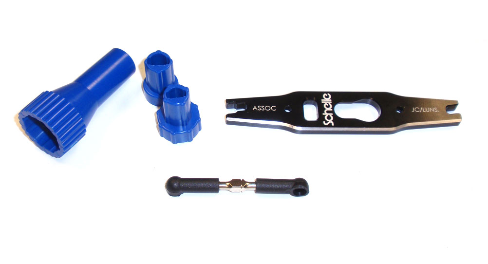
Building turnbuckles can be a pain sometimes, so I look for tools to help make this a not-so-horrible task. Two items I’ve found are Duratrax’s ball cup tool and Schelle Racing’s multi-turnbuckle tool. I won’t build turnbuckles without either of these. That said, build your drag link turnbuckle.
Step 11
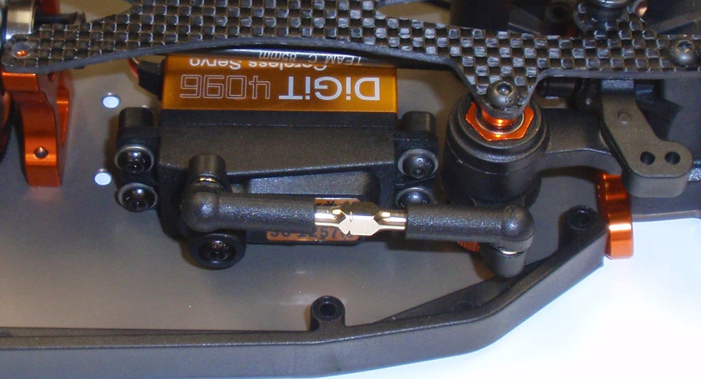
Finally, pop the turnbuckle into place.
Great job. Next step, the top decks.
Team C TM4 Online Build – Part 6
The TM4 uses a dual top deck with a center aluminum bulkhead cap. This allows for easier maintenance than a car will a full top deck. We’ll also be installing the front and rear shock towers and wing mounts.
Build Notes:
• If you choose, you can seal the edges of the carbon fiber top decks and shock towers with CA glue. This helps keep them from delaminating in the event of a crash.
• Because of the way the battery mounts, I had to dremel a pretty serious notch in the rear top deck to allow the plugs to attach to the battery. This shouldn’t be a bit issue with handling but be aware that if you do have a big crash, this could potentially be a weak point in the car’s backbone.
Step 1
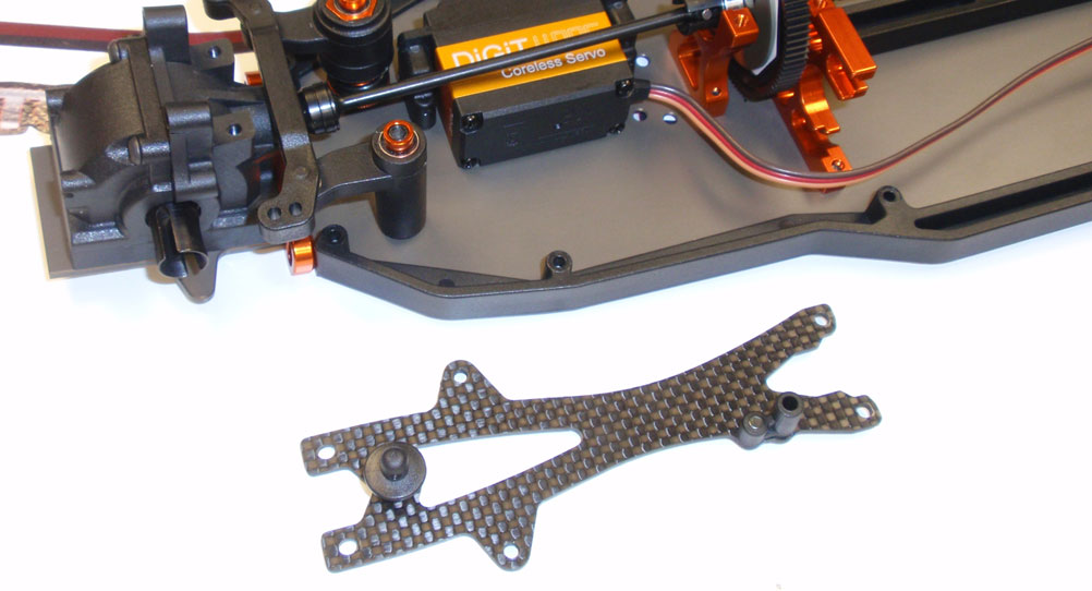
Assemble the front top deck, making sure the antenna mount is positioned on the left side of the deck. Place the two orange spacers on the steering posts and attach the top deck to the chassis.
Step 2
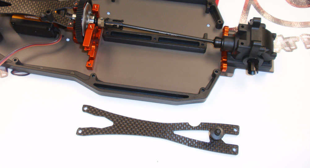
Assemble the rear top deck and attach it to the chassis. As you can see, I’ve had to notch the piece quite a bit to get the battery plugs to reach the battery. I would test fit whatever battery you are using to see how much you’ll need to do this. I could have reversed the battery to have the plugs up front, but then the notch would be closer to the attachment point; I figure this would make that point much weaker than having the notch more in the middle.
Step 3
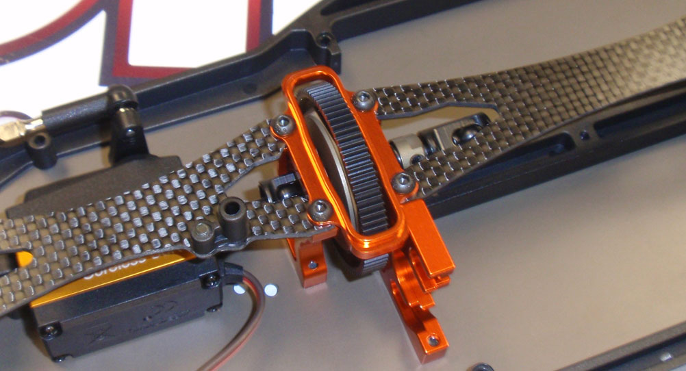
Bolt the aluminum cap onto the center bulkheads. It does have a top and bottom so make sure you test fit it prior to screwing it in place.
Step 4
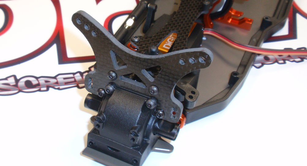
Attach the front shock tower to the front gearbox.
Step 5
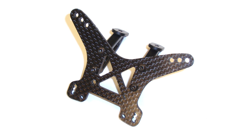
Attach the wing mounts to the rear shock tower. You can attach the mounts to either side; the tower is not directional.
Step 6
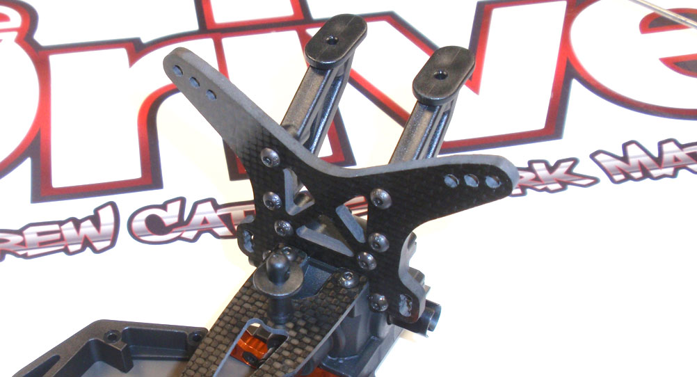
Attach the rear tower to the rear gearbox, making sure the wing mounts are to the rear of the car.
Pretty easy step! Next up is the suspension.
Team C TM4 Online Build – Part 7
The next step in the Team C TM4 build is assembling and attaching the front suspension.
Build Notes:
• Pay close attention to the left and right parts used in each step. It will be easy to mix these up but I’ll try and call them out as much as I can.
• The front droop screws are impossible to get to once the front suspension is attached to the car, so make sure you set both sides equal when installing.
Step 1
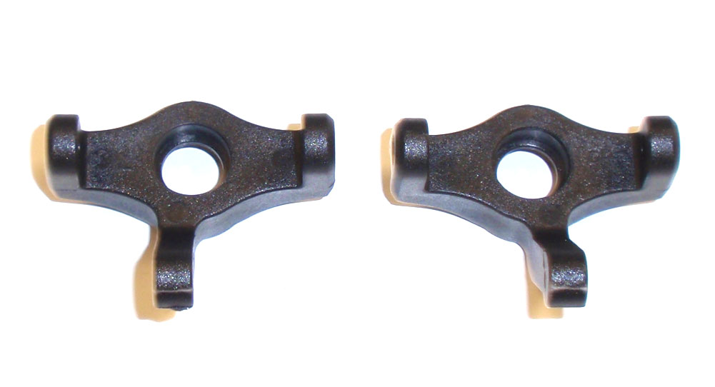
The first thing we want to do is discern the left and right steering block. The one on the left is the left-hand block, the one on the right is the right-hand block. Mine didn’t have L and R markings on them like the manual shows.
Step 2
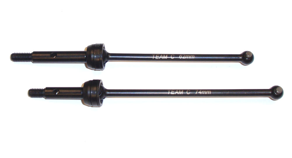
We need to discern the front and rear CVD’s as well. The front’s are 74mm, shown at the bottom; the rears are 62mm, shown at the top. The lengths are etched into the bones for easy identification.
Step 3
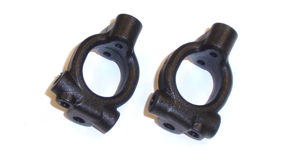
The front caster blocks are also directional, meaning there is a left and right one. These are easily identified by the 10R and 10L molded into the backside of them. Just make sure you put the 10R on the right side; the 10L on the left side.
Step 4
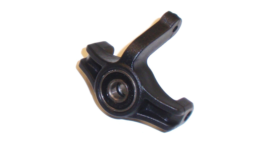
Let’s start by pressing a 5×13 and 5×10 bearing into each steering block. Keep track of the left and right blocks.
Step 5
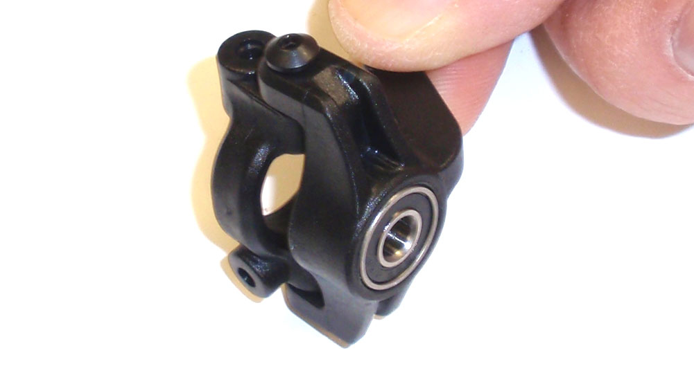
Attach the left steering block to the 10L caster block and the right steering block to the 10R caster block. Do not overtighten the screws; make sure the steering blocks rotate easily.
Step 6
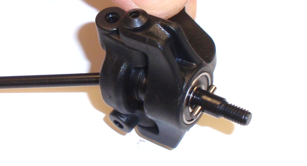
Insert the front CVD assembly (74mm ones) through the steering block. Slide the axle pin through the hole.
Step 7
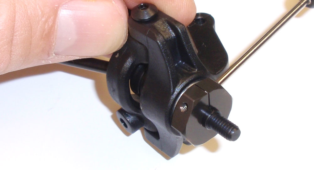
Attach the wheel hex and secure with the M2x5 screw. Be careful not to overtighten. Complete both sides.
Step 8
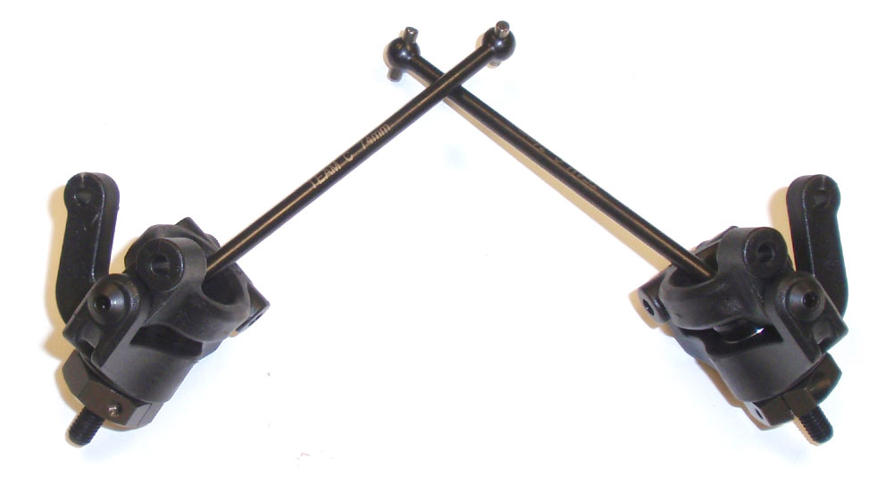
Here are your completed steering block assemblies.
Step 9
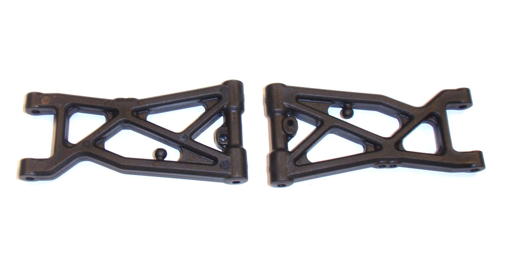
The front suspension arms are both the same so it doesn’t matter which side you install them on. Insert the M3x10 setscrew (the manual states a M3x8, but it should be a 10mm) into the droop hole in the arm. Screw it in so it’s about half way through the arm and an equal amount sticks out of both sides. This will be a good starting point, however as mentioned before it’s impossible to adjust when the assembly is complete.
Step 10
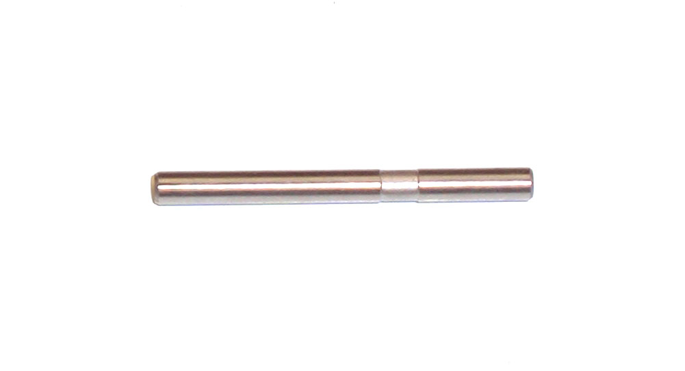
Locate the outer hinge pin. Note the groove recessed in it; this is where the set screw from the steering block will help capture it.
Step 11
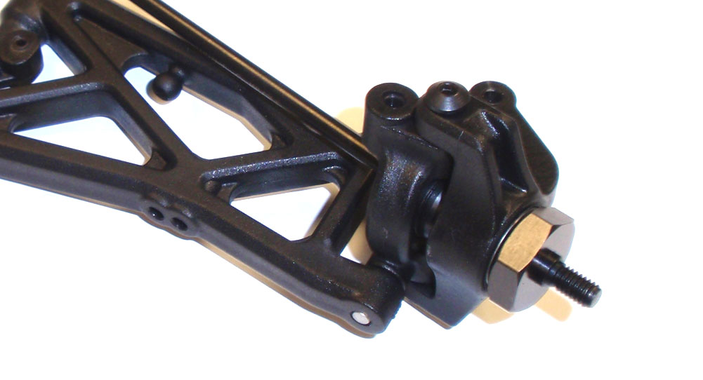
Slide the hinge pin through the arm and steering block assembly.
Step 12
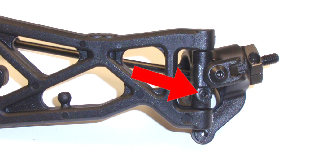
Screw the M3x3 setscrew into the hole in the bottom of the steering block. It SHOULD seat in the groove in the hinge pin. Do not overtighten; it’s easy to strip this hole out.
Step 13
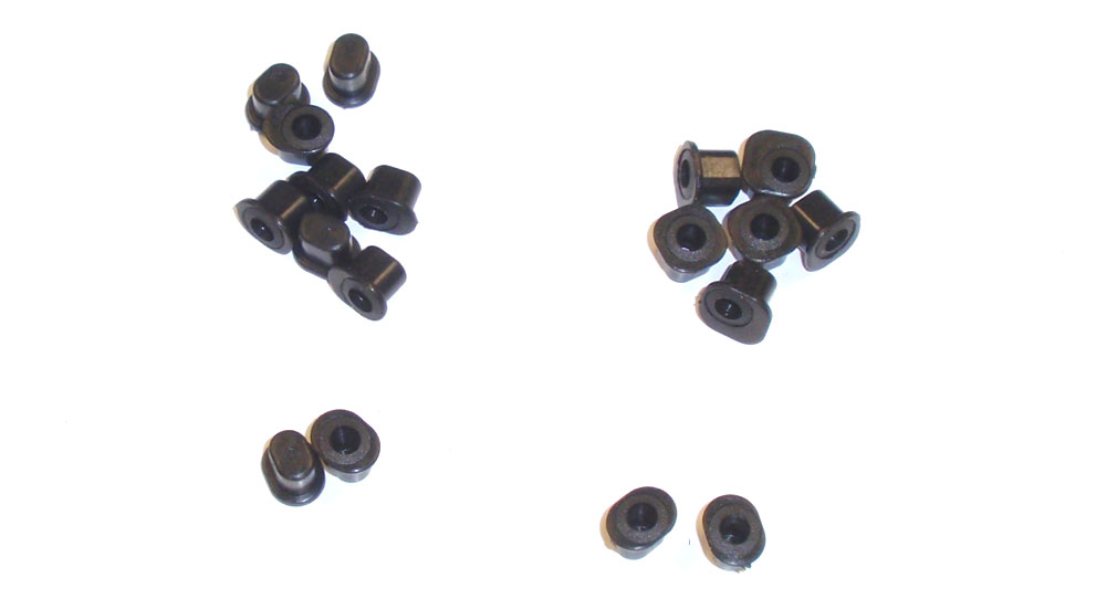
Locate and separate the hinge pin inserts. These inserts allow you to change kickup and roll centers on the TM4. For the build we’ll be using four of the 0° inserts – the hole will be dead center in the insert.
Step 14
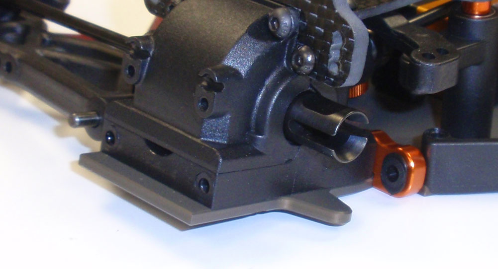
Press the 0° insert into the FR arm mount.
Step 15
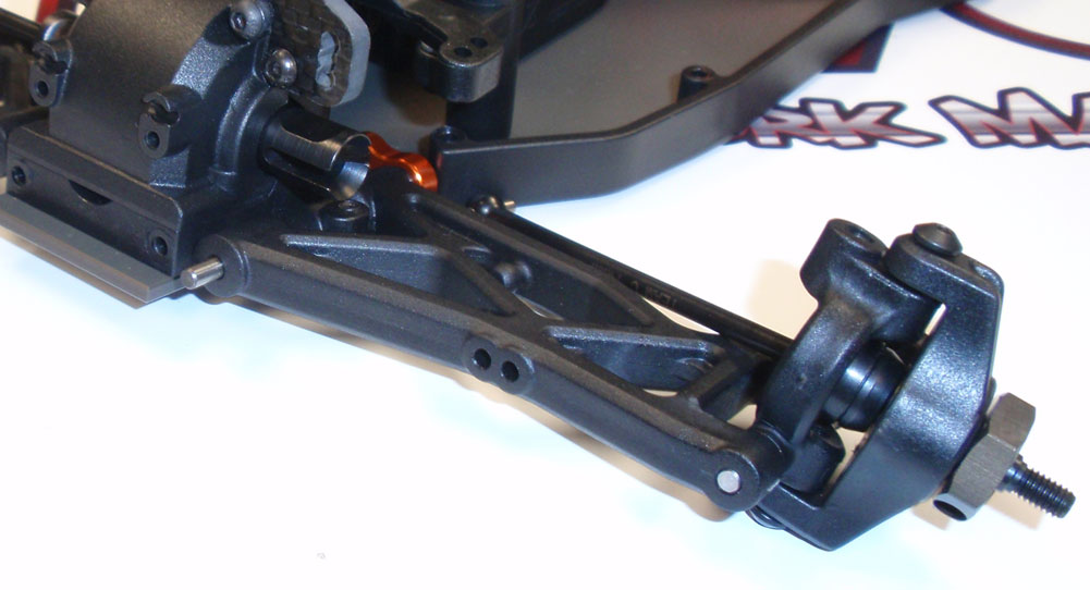
Slide the inner hinge pin through the suspension arm and into the 0° insert in the FR arm mount. Make sure you are mounting the left suspension arm assembly to the left side of the car and vice versa.
Step 16
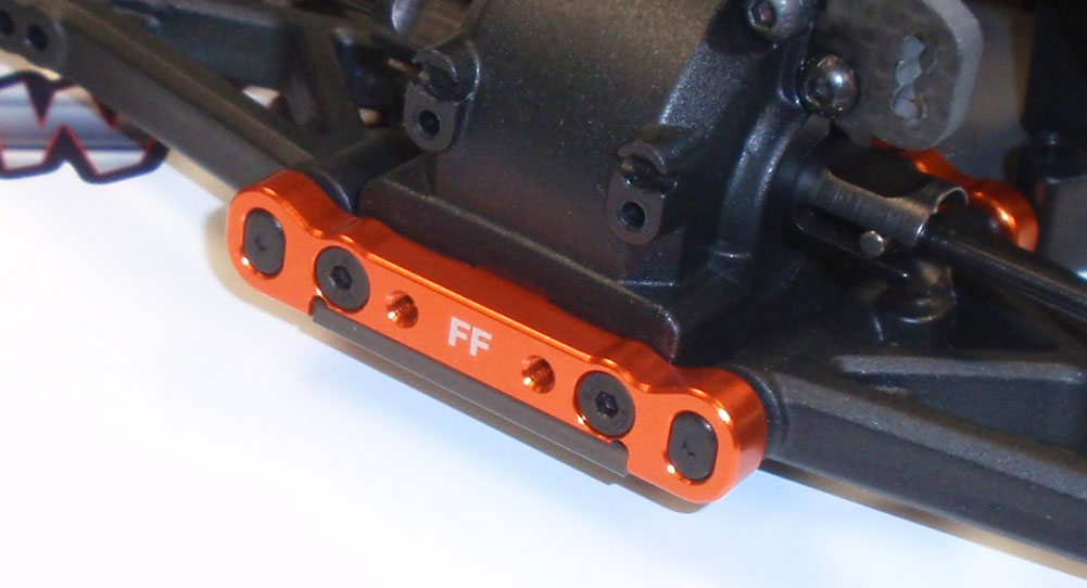
Press another 0° insert into the FF arm mount and attach it to the front of the bulkhead, capturing the front of the hinge pins. Screw it into place.
Step 17
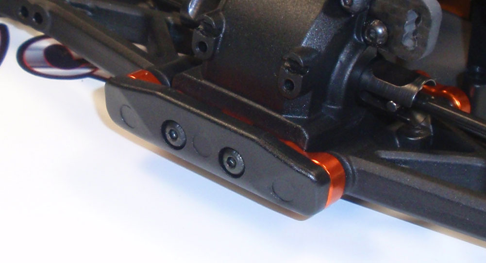
Attach the front bumper.
Step 18
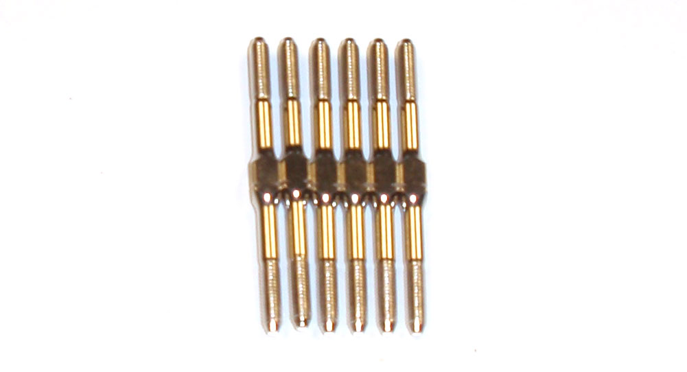
Thank you Team C for supplying 6 turnbuckles that are all the same length. This makes it much easier to build. No, mine didn’t come gold … that’s the awesome lighting in the room.
Step 19
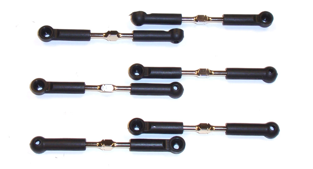
Build 6 turnbuckles; 2 steering, 2 front camber and 2 rear camber. Make sure you keep them separated so you know which goes where.
Step 20
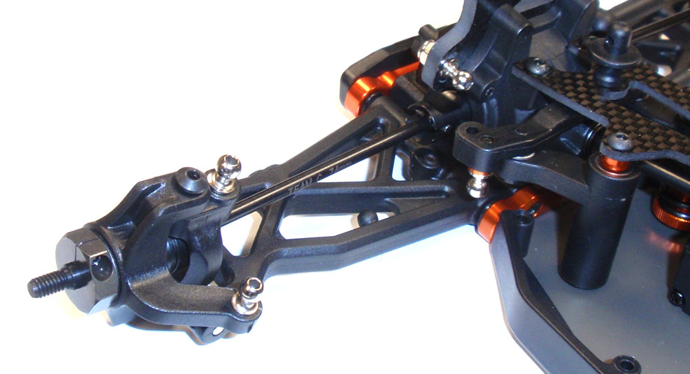
Screw a short ballstud into the steering arm and a long ballstud into the caster block, steering rack (with a 3×5 washer) and shock tower (captured by a M3 nut). BE CAREFUL tightening the short ball stud (in the steering arm). Once I completed this, I noticed some stress marks forming.
Step 21
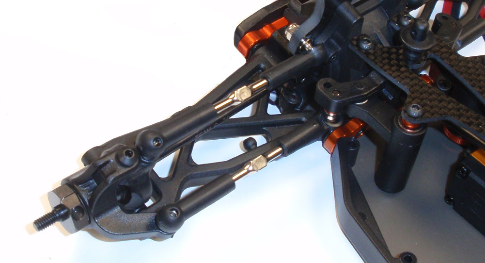
Insert the CVDs into the outdrives and pop the front caster links and steering links onto the front of the TM4. You did keep track of which ones were which, right?
There ya go; front suspension complete. Make sure the front arms move up and down without binding.
Team C TM4 Online Build – Part 8
In Part 8 of the Team C TM4 build we’ll be assembling and installing the rear suspension. Pretty straightforward.
Build Notes:
• There were a few manual mistakes that I found, mainly the droop setscrews and anti-roll bar setscrews being mixed up. The manual also calls out a 1.2mm rear anti-roll bar, however a 1.1mm one was included. I’ve addresses these differences in their corresponding build steps.
Step 1
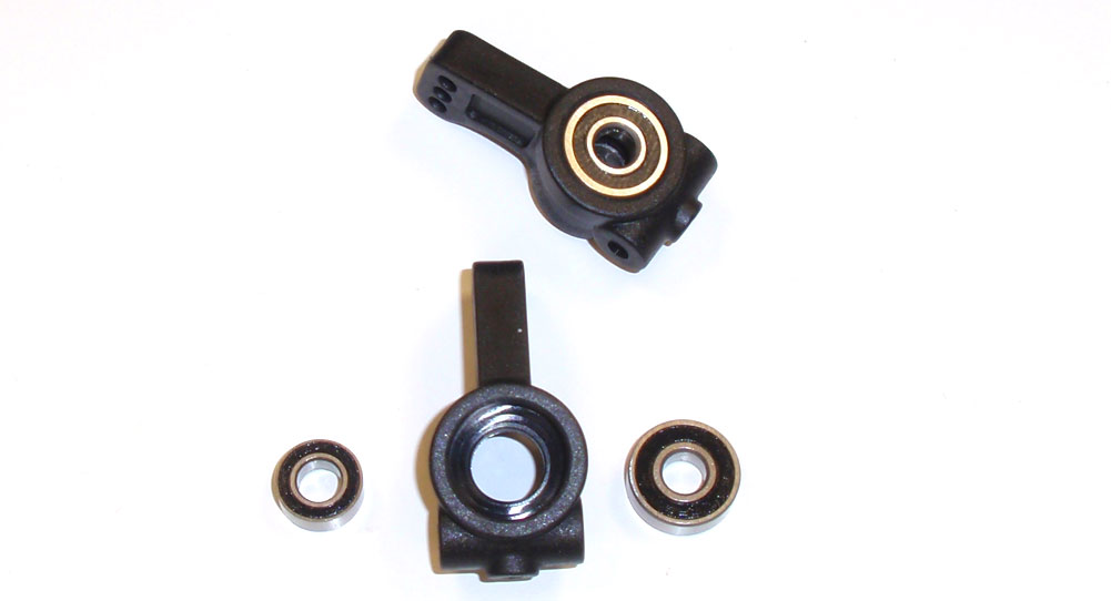
Let’s start by pressing a 5×13 and 5×10 bearing into each rear hub. The hubs are not directional so there is no need to worry about which side they go on.
Step 2
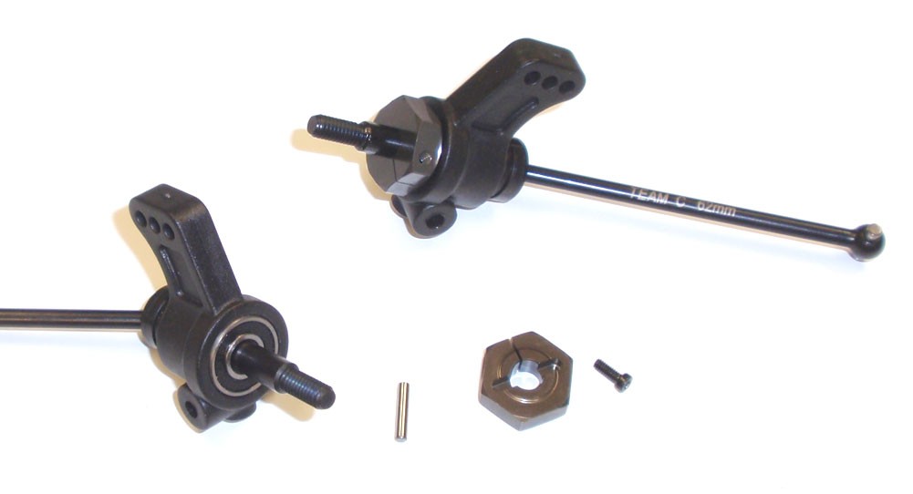
Insert the 62mm CVDs into the rear hubs. Slide the axle pin in place followed by the wheel hex. Secure the wheel hex with the M2x5 screw.
Step 3
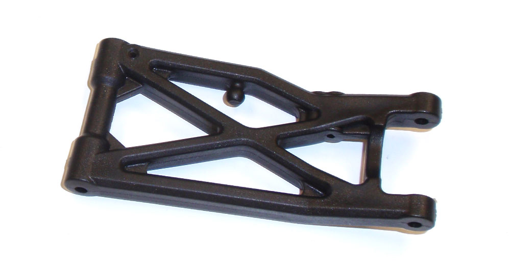
The rear suspension arms come in a left and right gullwing design, so pay attention here. Using a M3x10 setscrew (instead of the M3x8 the manual says), insert it into the rear arms. You can get the M3x8 screws from the anti-roll bar link parts.
Step 4
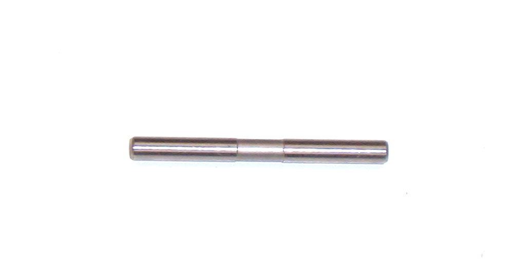
Also, find the rear, outer hinge pins. You’ll notice the recessed groove where the setscrew will seat.
Step 5
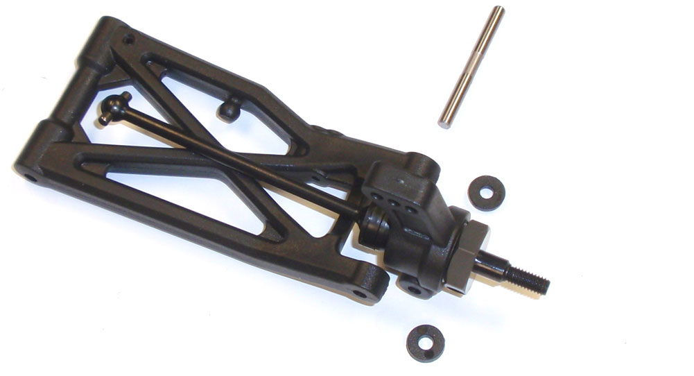
Slide the outer hinge pin through the suspension arm and rear hub. There are 2 spacers that allow you to adjust the overall wheelbase of the TM4. For now, let’s put one on each side of the rear hub. Like we did with the front, screw a M3x3 setscrew up through the bottom of the rear hub to capture the hinge pin. Don’t overtighten!
Step 6
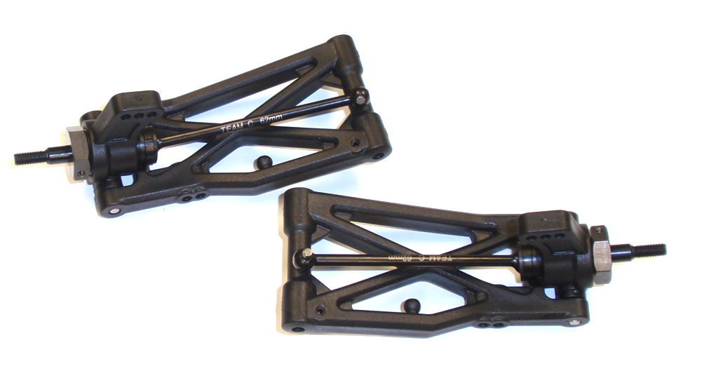
Your assembled rear suspension arms should look like this.
Step 7
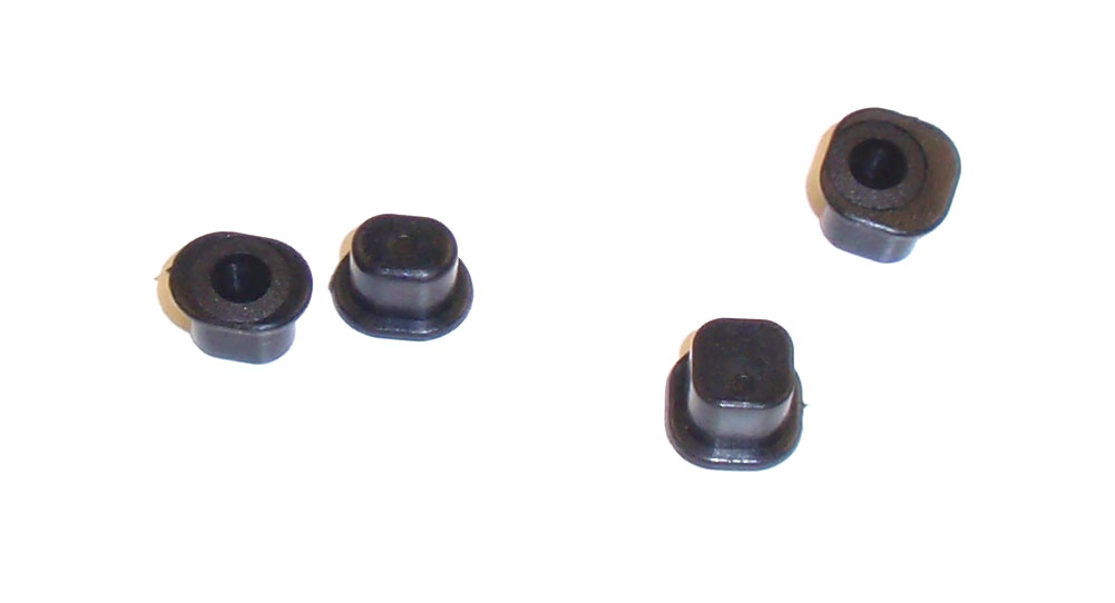
As with the front, the rear uses inserts in the arm mounts. These are used to adjust anti-squat, roll center and rear toe. We’ll be using the 0° RF inserts and 1° RR inserts.
Step 8
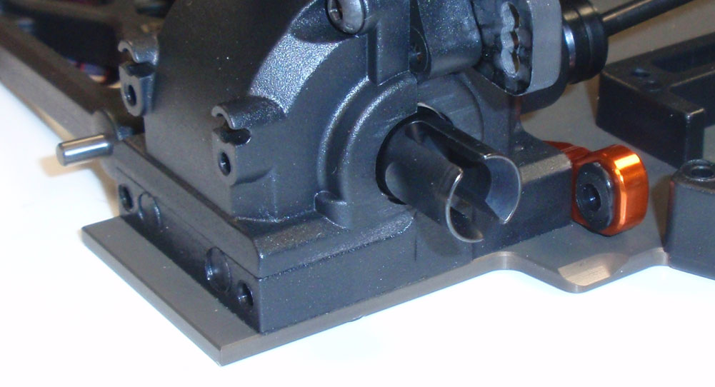
Press the 0° inserts into the RF arm mount.
Step 9
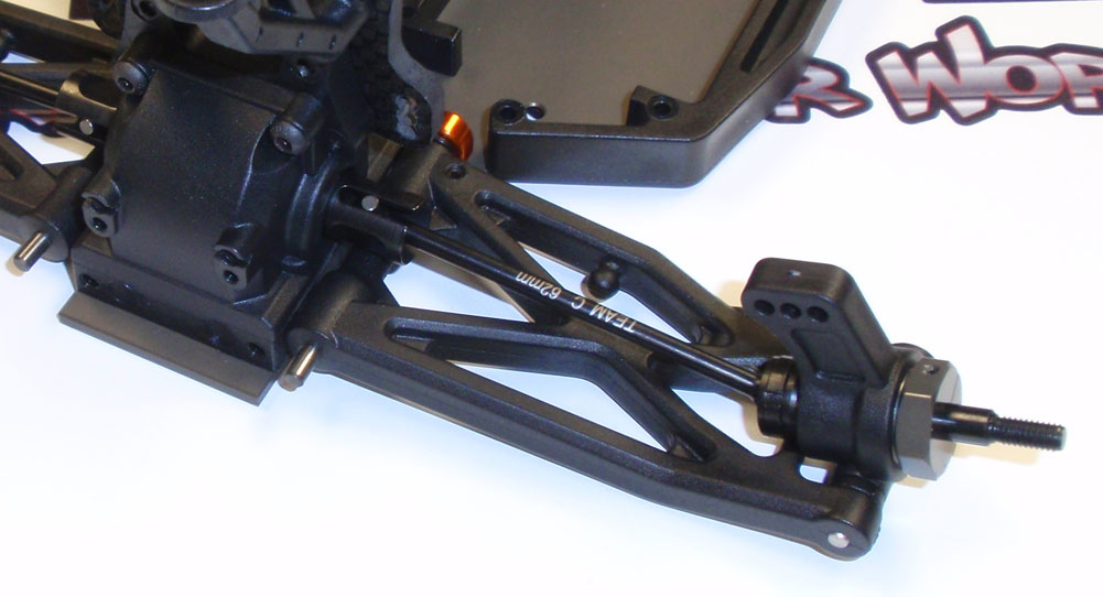
Slide the long, inner hinge pin into the through the rear arm assembly and into the RF arm mount. Pay attention to the direction of the rear arms; the shock mounting holes in the arm should face forward.
Step 10
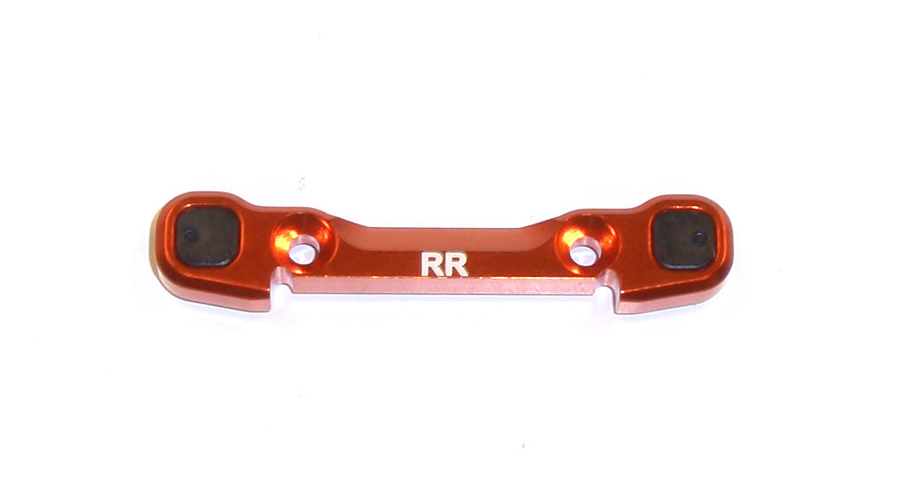
Press the 1° inserts into the RR arm mount. Note that the ‘indicator’ on the insert should face out, like the picture.
Step 11
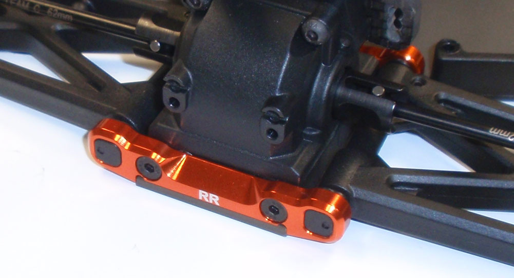
Slide the RR mount into place and over the hinge pins, securing it with the M3x12 screws.
Step 12
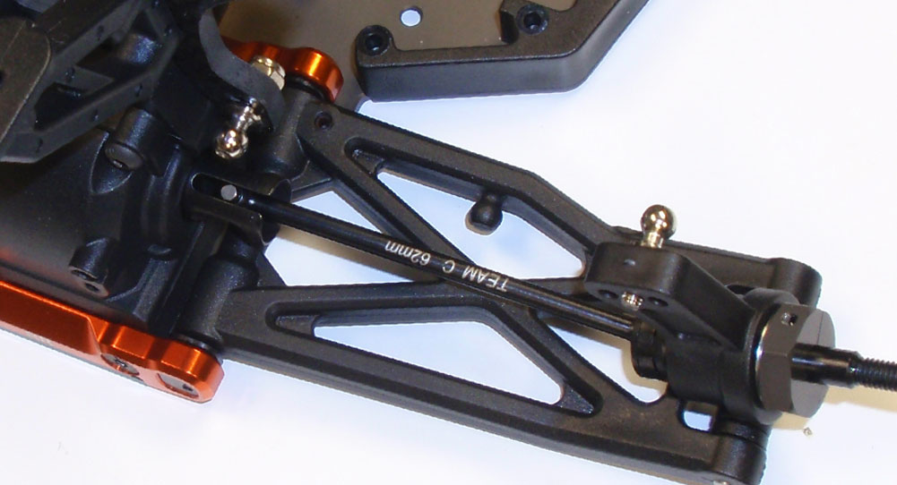
Screw one long ballstud into the center hole in the rear hub and one into the middle hole in the shock tower. Secure the shock tower ballstud with a M3 nut.
Step 13
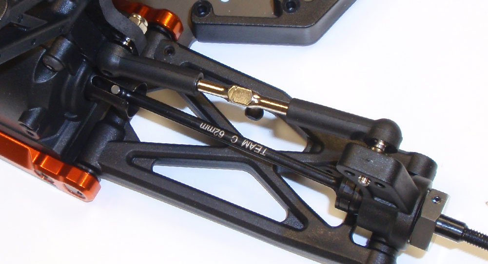
Key the CVD into the outdrive and pop the rear turnbuckles on that we built in Step 73.
Step 14
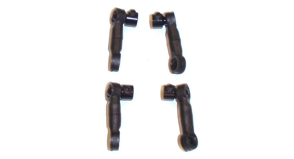
Build 4 anti-roll bar links. You want to use a M3x8 setscrew instead of the M3x10 the manual says. These were the ones we were going to use as droop screws. We’re going to attach the front bar first, then the rear.
Step 15
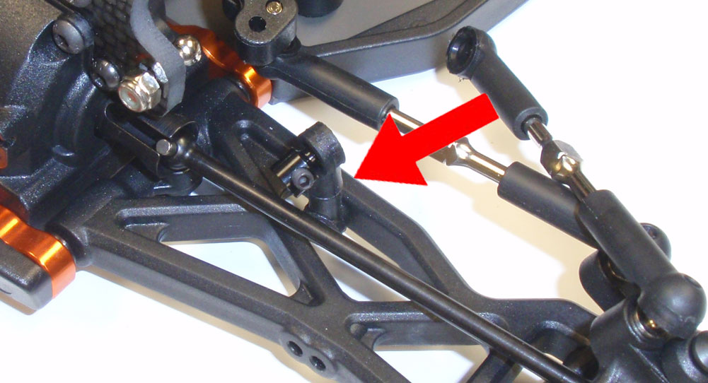
Pop the anti-roll bar links onto the balls molded into the front arms. Make sure the anti-roll bar ballstud faces the front of the car. I popped the front camber link off so you could see the anti-roll bar mount a little better.
Step 16
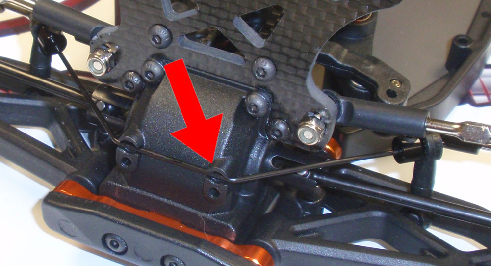
Using the 1.2mm bar, slide the ends into the anti-roll bar mounts you just attached to the arms. Press the bar into place where the arrow shows.
Step 17
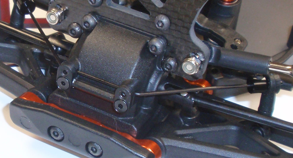
Set the anti-roll bar cap into place and secure. Screw the M3x3 setscrews into place until the JUST TOUCH the bar, then back them off a teeny, weeny bit. They are there to keep the bar from moving back and forth, not to hinder it’s rotation.
Step 18
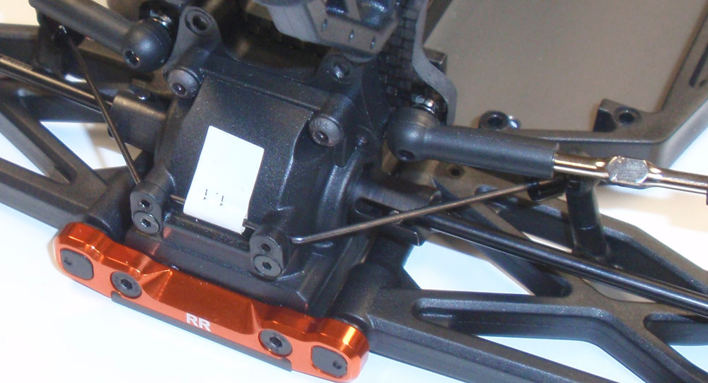
Follow the same procedure to attach the rear anti-roll bar. You will be using a 1.1mm bar in the back even though the manual says it’s a 1.2mm (my rear one was labeled, however my front wasn’t).
Great job. A few extra build steps than we’ve encountered so far but it’s starting to look like a real car now!
Team C TM4 Online Build – Part 9
The Team C TM4 comes with a great set of threaded aluminum shocks. They feature a bottom load cartridge, multiple pistons and bleeder caps for easy building.
Build Notes:
• We’ll be using shock fluid in this step so it’s a good idea to have some paper towels or rags handy. Also, you might want to put something down on your workspace before building. You don’t want your mom/girlfriend/wife pissed when you get shock fluid all over her nice table.
Step 1
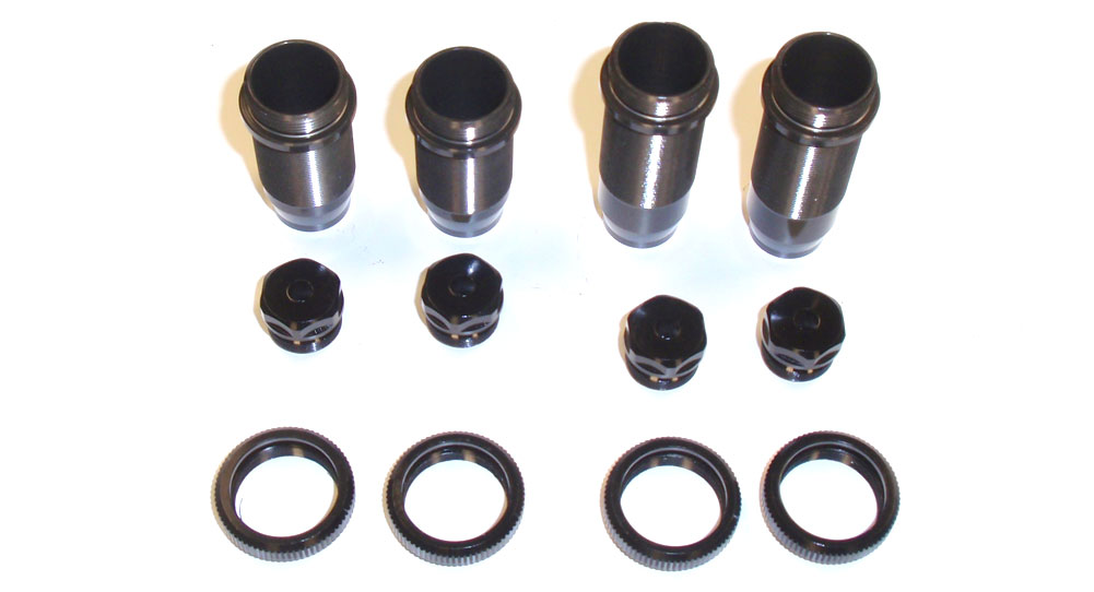
Let’s first identify all the parts we’ll be using. On the left are shorter shock bodies, used for the front. The longer shocks bodies on the right are for the rear. The cartridges and spring adjusters are the same for both.
Step 2
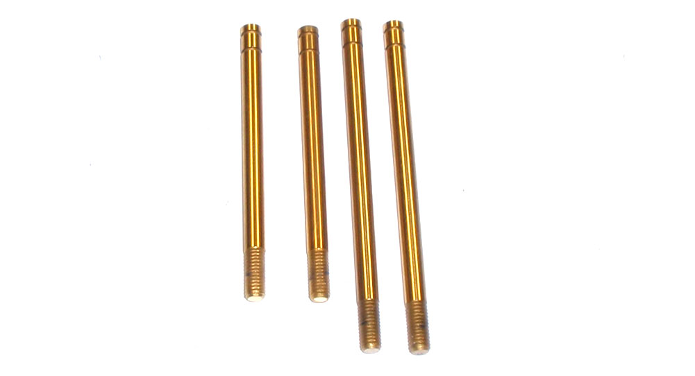
Like the shock bodies, the two shorter shock shafts are for the front, the longer ones for the rear.
Step 3
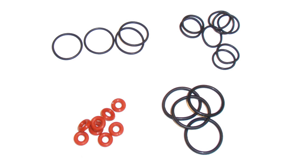
There are also a bunch of o-rings included. From the bottom left (and rotating clockwise), the red o-rings go inside the shock cartridge, the thin larger o-rings go on the outside of the top of the shock bodies (cap side), the smaller o-rings go on the outside of the lower cartridge and the thick, larger o-rings go inside the spring adjusters. Separating them will make it easier when the steps call for them.
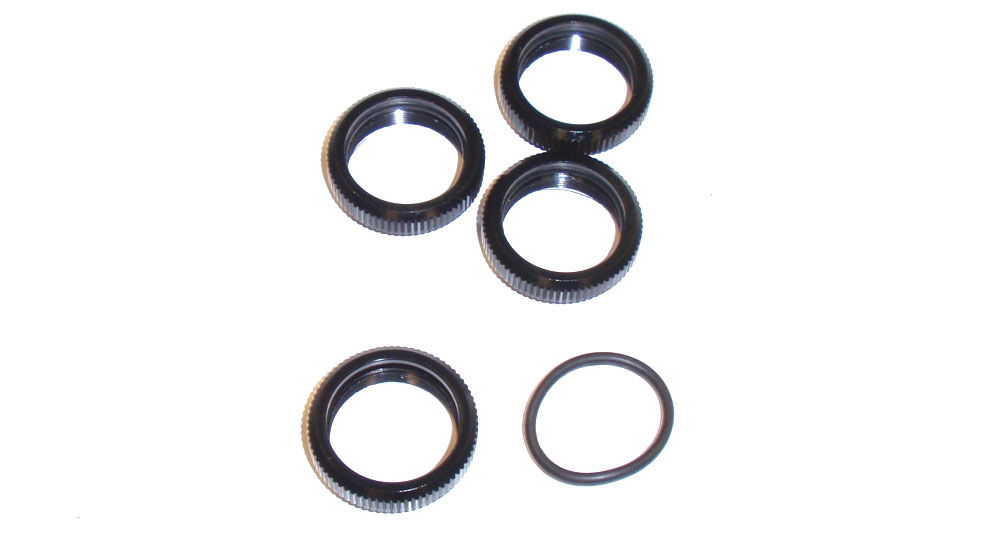
Step 4
Grab the 4 thick, large o-rings and carefully insert them into the groove in the spring adjuster. We want to do this step up front; if you get oil on your fingers (and then on the o-rings) they become a major pain to install.
Step 5
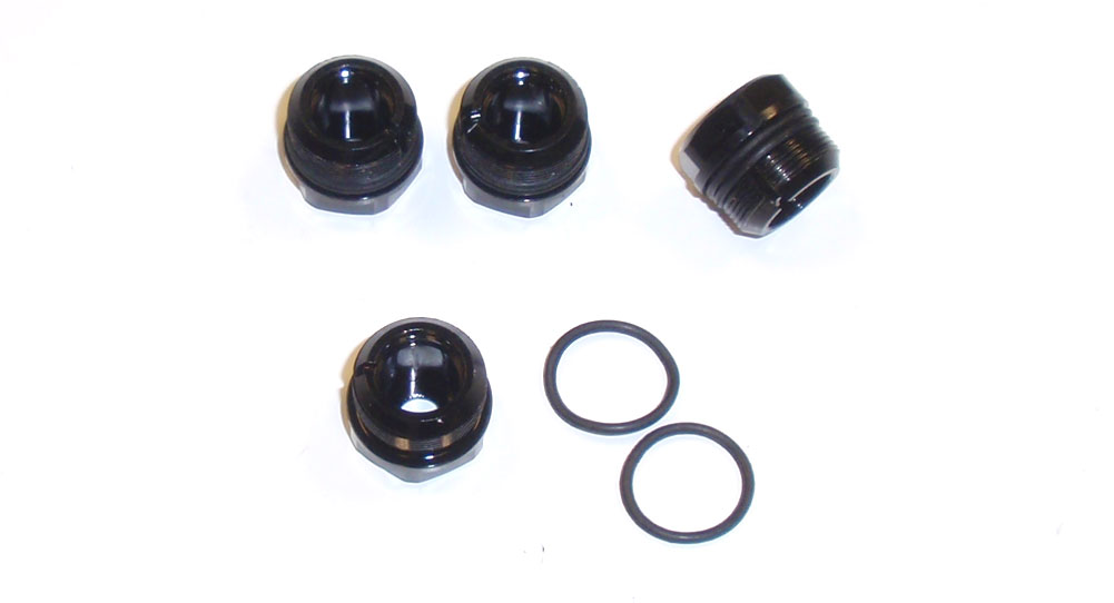
Take the 8 smaller o-rings and loop them over the cartridges. 2 will go on each cartridge.
Step 6
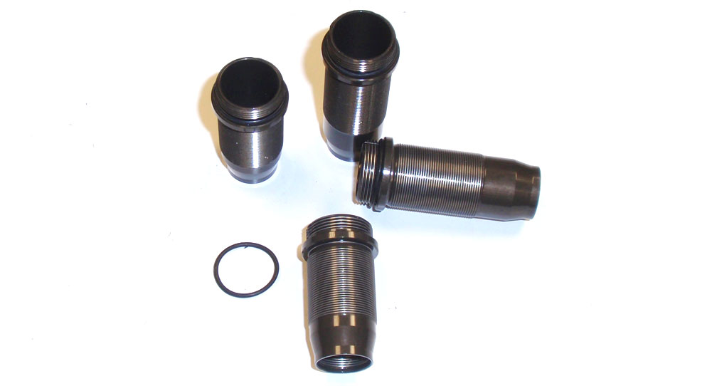
Finally, take the thin, larger o-rings and loop them over the cap-side of the shock bodies.
Step 7
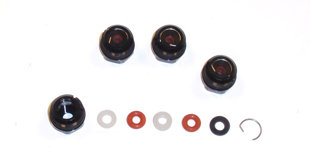
Next is the shock cartridge. I’ve laid out the parts in the order they will be installed. Everything goes together easily, however the snap ring might cause you a little grief. There really is no ‘best’ way to do it; just slide an end in and carefully force the other side in. Just make sure it snaps completely into the grooves in the cartridge.
Step 8
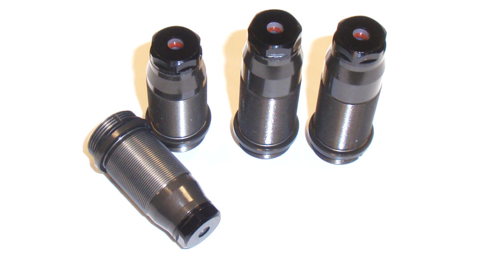
Screw the cartridges on the shocks. Be careful not to ‘pinch’ the o-ring outside the shock body. If you apply a small amount of oil to the outer o-ring, it will help it seat better.
Step 9
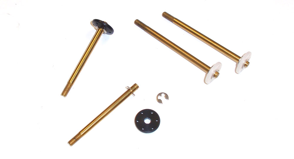
Assemble the 4 shock shafts. The front shafts get the black pistons, the rears get the white.
Step 10
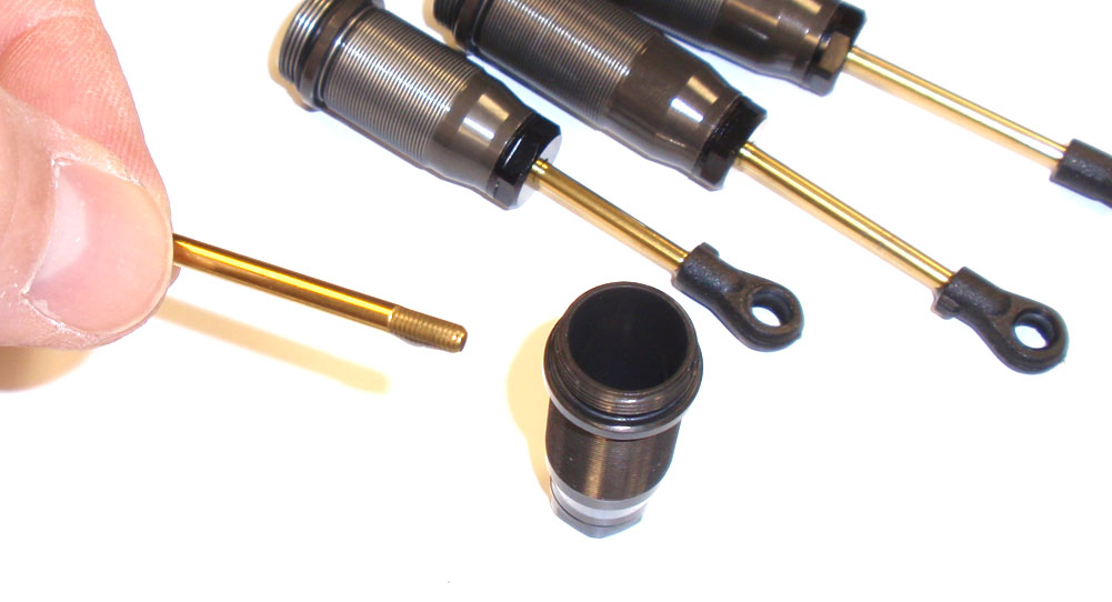
Put a light drop of oil onto the threads of the shaft and slide it into the shock body assembly. Press SLOWLY through the cartridge so you don’t tear the internal o-rings. Once through, screw the shock eyelet onto each shaft.
Step 11
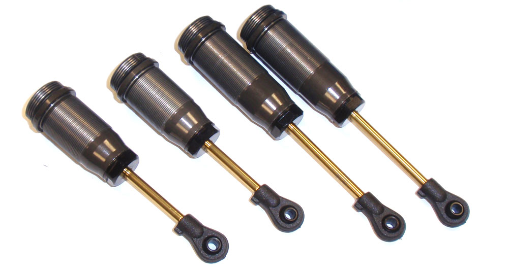
Slide the shaft up and down a few times to coat it with oil. Pop a bushing into each shock eyelet.
Step 12
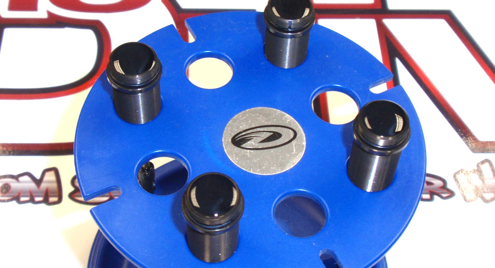
Fill your shocks to the top with oil. Plunge the shaft a few times, slowly, until all the bubbles rise to the top (the oil level will probably go down a bit as well). Place the shocks in a shock stand (I’ve listed a few at the bottom of this page) and fill them back up with fluid. Let them site for a few minutes while the oil rise.
Step 13
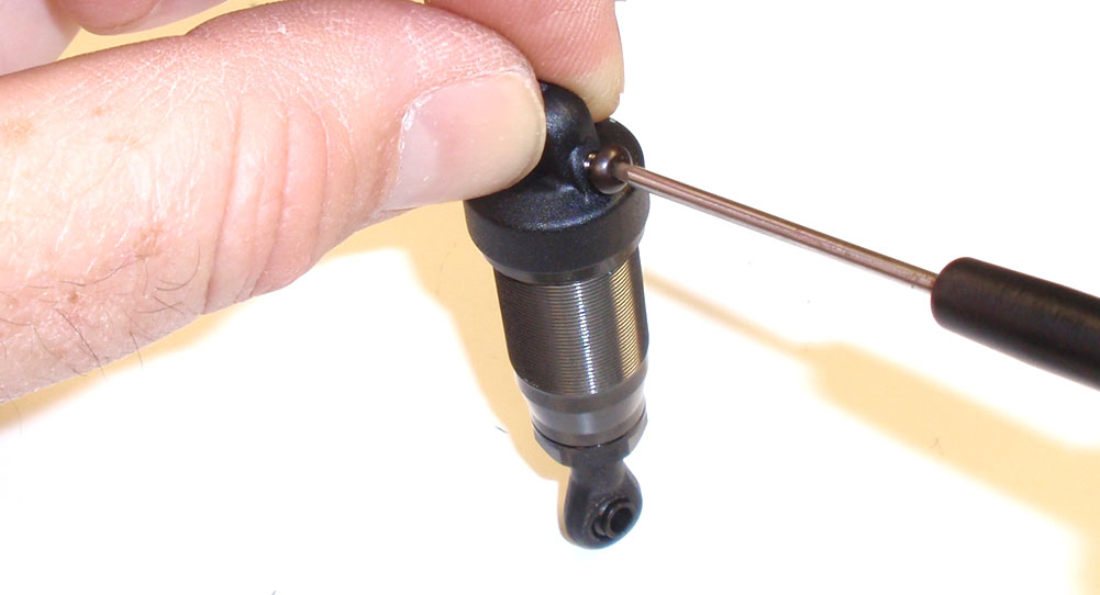
Screw the top onto the shock. Slowly compress the shock; you should see some oil come out of the bleeder hole in the cap. Once compressed, screw the bleeder screw into the cap. Clean up any excess oil that has leaked out.
Step 14
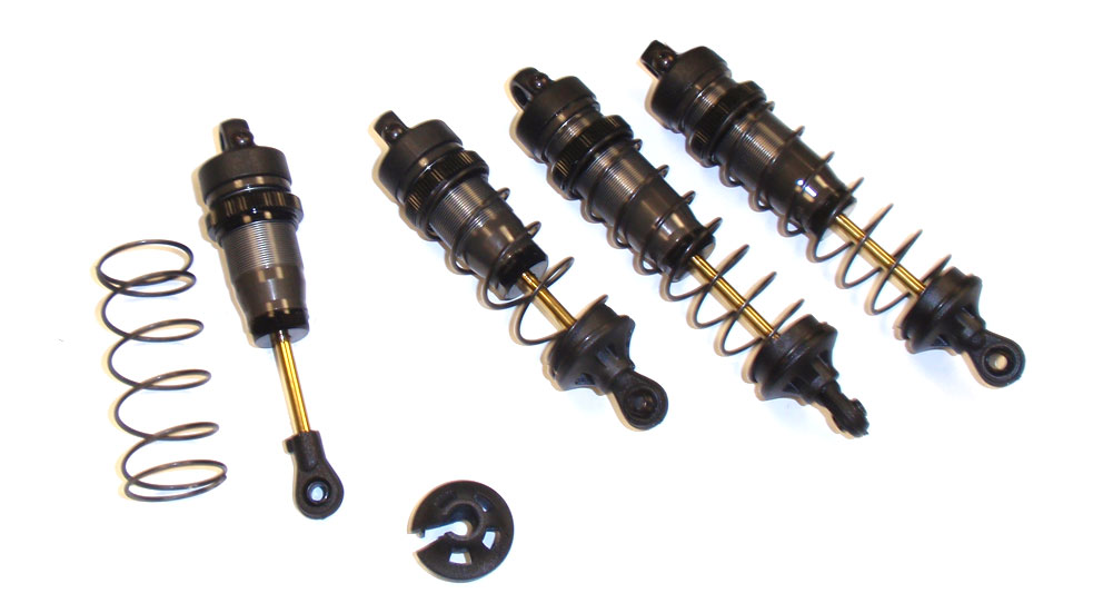
Thread the spring adjusters onto the shocks followed by the springs (shorter ones up front, longer in the rear) and lower spring retainers (key the opening in the retainer to the nub on the eyelet). Make sure the front spring adjusters are set equal, then set the rear spring adjusters equal. You can fine tune these when you set the ride height at the end of the build.
Step 15
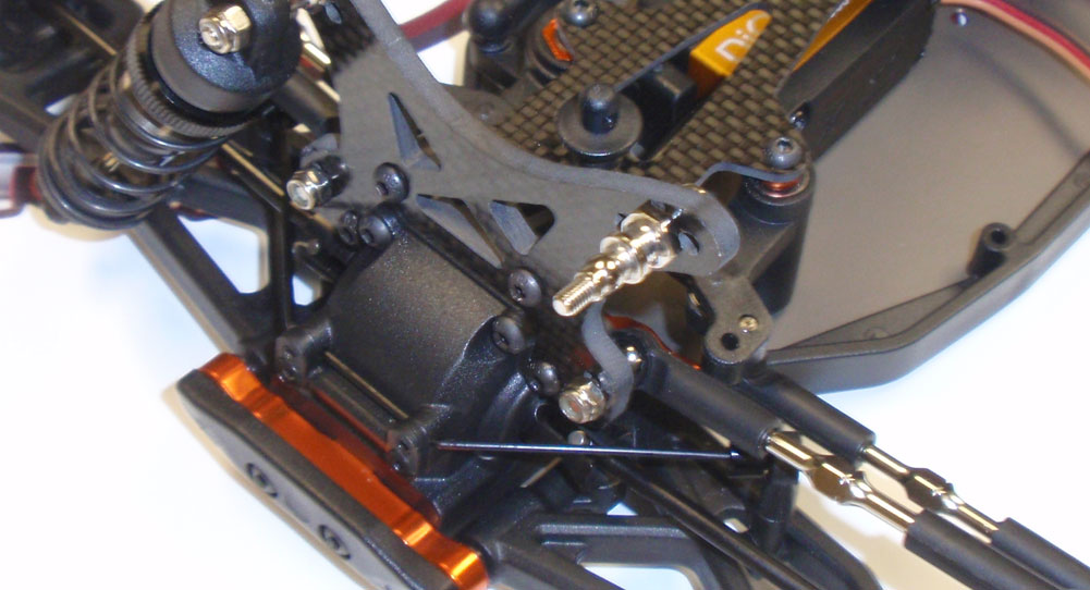
Attach the upper shock mount to the middle hole in the front tower.
Step 16
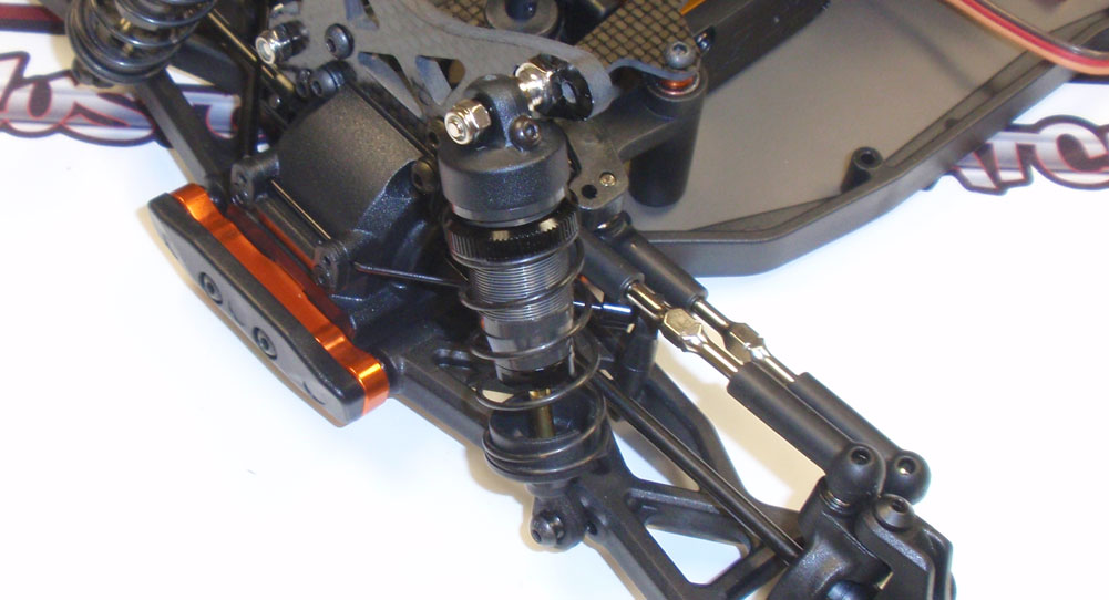
Bolt up your front shocks. Use the inside hole in the suspension arm.
Step 17
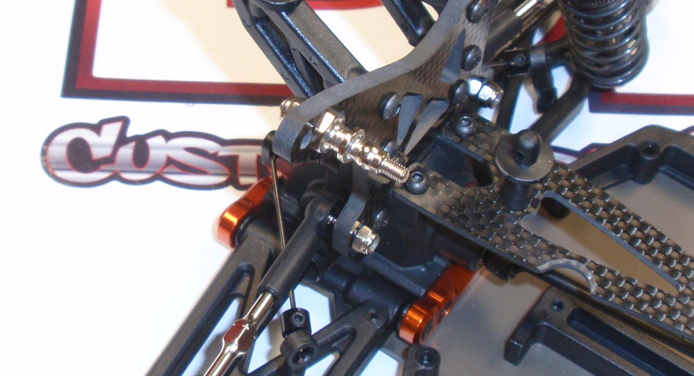
Attach the upper shock mount to the middle hole in the rear tower.
Step 18
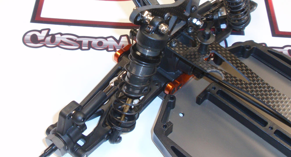
Bolt up your rear shocks. Use the inside hole in the suspension arm.
Awesome job! Compress each corner a few times to make sure everything feels silky smooth!
Team C TM4 Online Build – Part 10
You need to supply your own electronics with the Team C TM4, so we’ll be dropping in some old favorites; Savox, Hobbywing and Racer’s Edge. We’ll be keeping everything in line with Futaba’s new 4PX radio system.
Build Notes:
• None.
Step 1
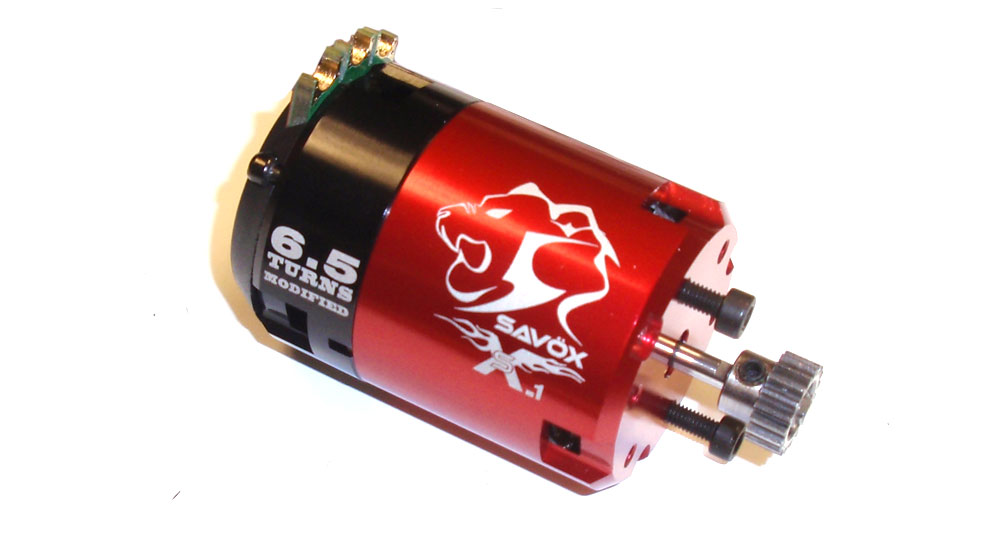
The first step is to find out what pinion gear you’ll need for the motor you are running. There is a small chart in the manual that gives you a good idea where to start. Attach the pinion to the motor and thread the pair of M3x8 screws in about 1/2 way.
Step 2
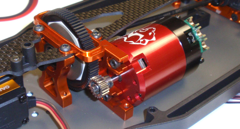
Wrangle the motor into the center mount as shown. If the motor doesn’t slide it easily, back the two M3x8 screws off a 1/4 turn and try again. Once in, set the gear mesh and tighten down the screws. Note the angle of the motor and where the motor wires will attach. This is important that you don’t have the motor twisted to far over that these tabs come in contact with the top deck.
Step 3
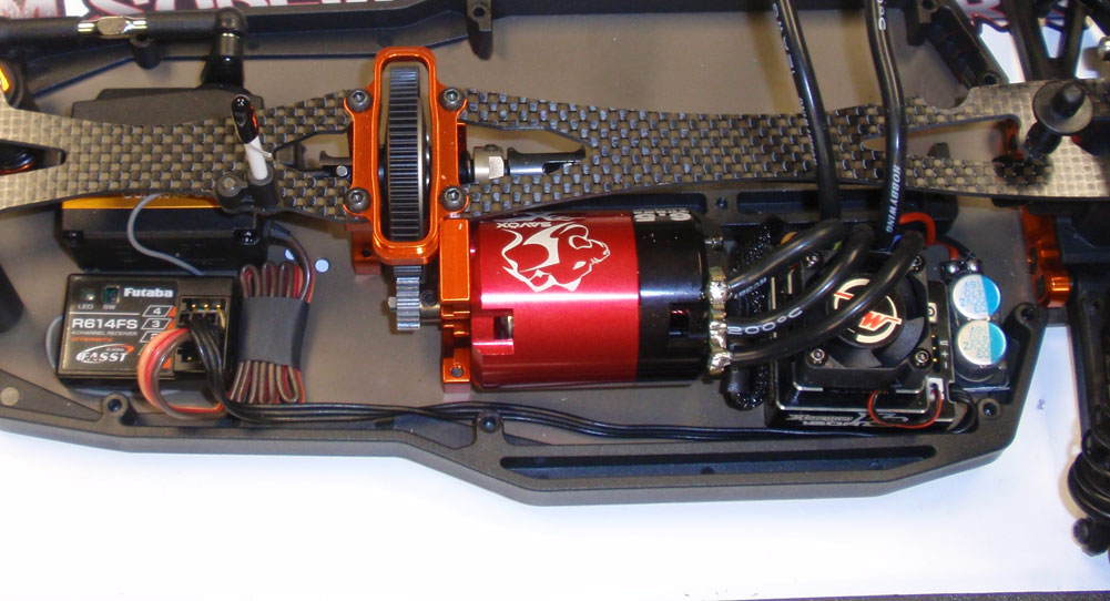
Install your receiver and ESC and complete the wiring. Your setup may vary a bit depending on where you mount your electronics, but these are the suggested locations.
Step 4
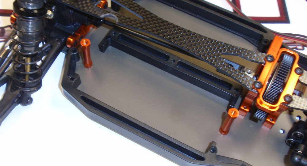
Attach the two battery posts. A dab of threadlocker is suggested here.
Step 5
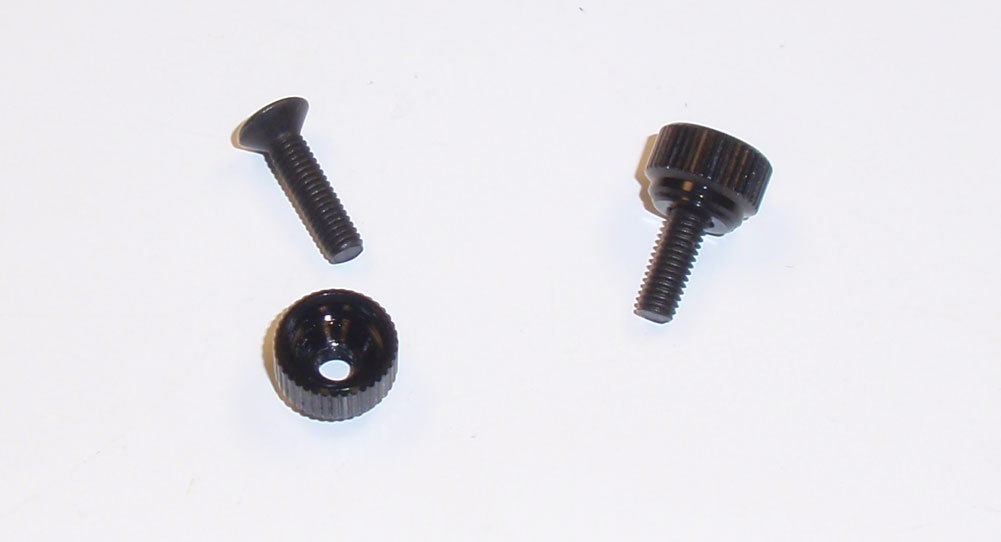
Assemble the two battery thumbwheels. A dab of threadlocker is suggested here as well.
Step 6
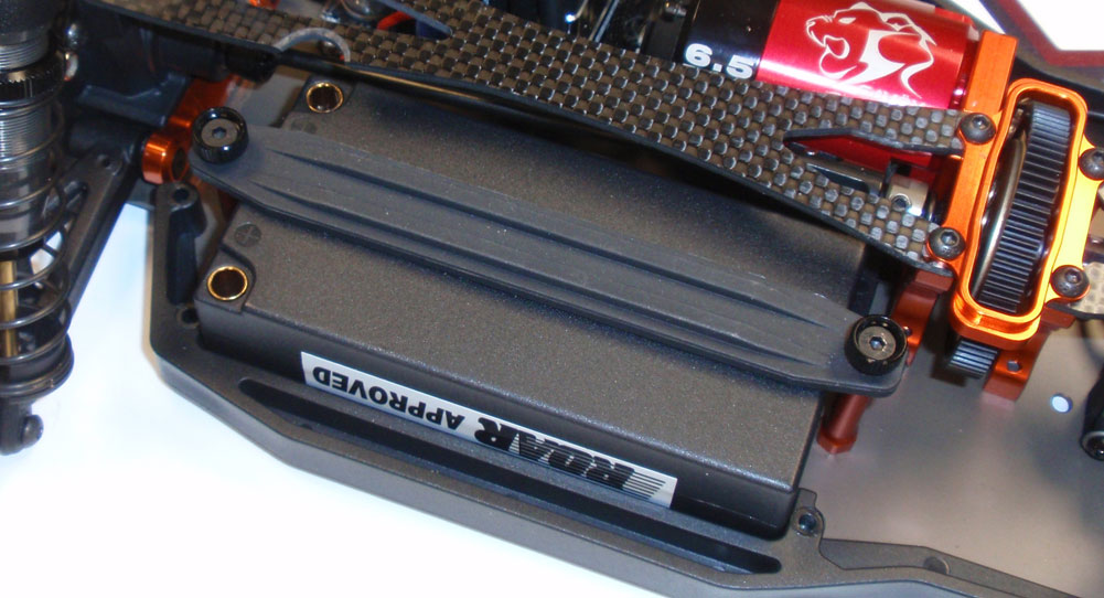
Drop your battery into place and secure with the battery strap and thumbwheels. You can now see the why the notch was needed in the top deck for the battery plug.
You can, at this time, fire up your TM4 to make sure everything works well.
Team C TM4 Online Build – Part 11
The final step in our Team C TM4 build is installing the wheels/tires and body.
Build Notes:
• You’ll be using CA glue to mount the tires to the wheels. CA glue can be nasty stuff if you treat it wrong, so please be careful not to glue your fingers together, or any other body parts.
Step 1
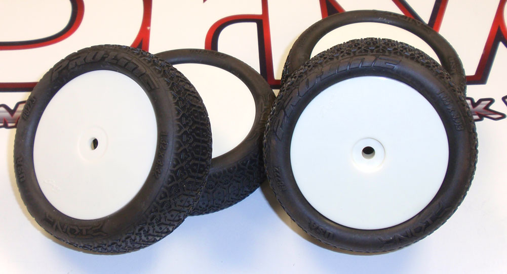
The TM4 doesn’t come with tires, allowing you to use whatever tires work best at your track. I’m mounting up some Proline IONs.
Step 2
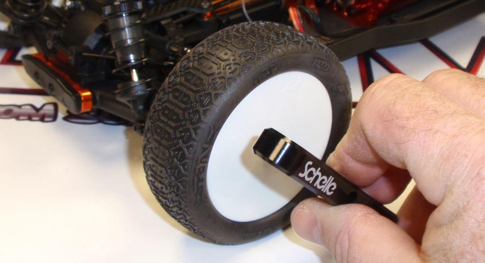
After the glue has dried, mount the skinny tires to the front, the wider ones to the rear. Schelle Racing has a cool wheel wrench that works great.
Step 3
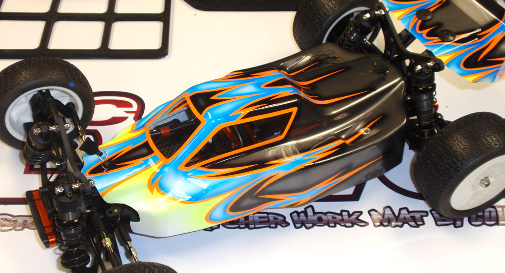
Paint, cut out and mount your TM4 body and wing. Secure the body with the pair of body clip (with handy pull tabs). Secure the wing with the M3x10 screws and washers.
I’d like to give a special shout out to Larry Genova at Kustom RC Graphics for his amazing paint job on the TM4. Check out his site; he does some amazing work!
There you go, a complete and ready to race 4WD buggy. Add some stickers and get out on the track!

