
TLR 22SCT Online Build

Modeled after the award-winning (and race-winning) 22, TLR’s 22SCT takes Short Course racing to a new level. Buildable in either RM (Rear-Motor) or MM (Mid-Motor) configuration, the 22SCT allows the driver to fine tune the entire chassis to track conditions.
I had a chance to race the 22SCT at the 2013 Short Course Nats and absolutely LOVED it. Having not raced in awhile and competing against some pretty heavy competition, I was able to qualify 6th in the A-Main. In fact, I took the lead on lap 2 and held it for about 4 laps. Strong winds and my lack of concentration dropped me back to 5th…but this was no fault of the truck. I’ll be practicing up this year in preparation for the 2014 Nationals.
Anyway, this truck was a fun build. Follow along as I go from a box of bags to a fully built track terror!
TLR 22SCT Online Build – Part 1
The 22SCT is a pretty free-flowing build. Up front it has us installing the servo and steering rack, so let’s get started.
Build Notes:
• Pay attention to the servo chart on page 12. This will help you decide which shims you will need in order to correctly space your servo.
Step 1
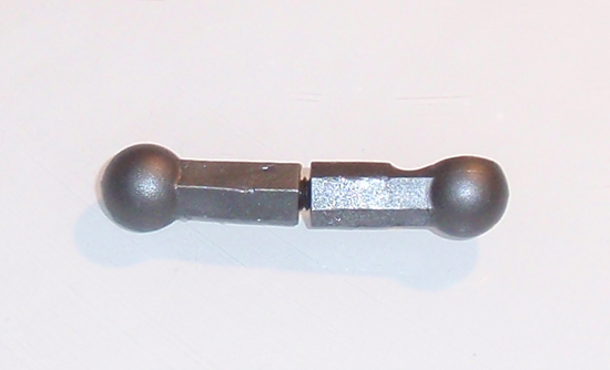
The first step is to build the drag link as shown. While the manual shows the drag link ball ends touching, this actually made my link shorter than 33.7mm. I twisted it out until it measured 33.7mm.
Step 2
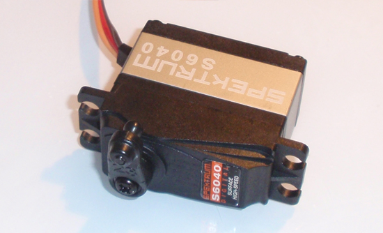
For this build I will be using one of Spektrum’s S6040 servos. This is a high power servo purpose built for racing so it will be perfect for my 22SCT. Attach the ball end to the appropriate servo horn as shown. If you have the ability to, I would suggest running some power to it to make sure the the horn sits at a 90 degree angle to the servo case.
Step 3
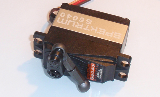
Pop the drag link into place.
Step 4
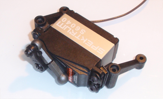
Using the correct shims, attach the servo mounts (and shims) to the servo. Do not tighten down just yet.
Step 5
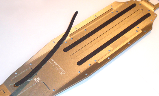
Pull the 3 strips of foam tape and set them into the grooves on the chassis as shown.
Step 6
Attach the side rails to the chassis.
Step 7
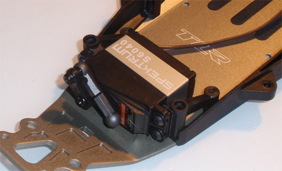
Attach the servo assembly to the chassis. Once you have mounted the servo mounts to the chassis, you can tighten up the screws that hold the servo to the mounts.
TLR 22SCT Online Build – Part 2
Part 2 of our build revolves around the steering system and front bulkhead of the 22SCT. The steering is quite unique, utilizing a sliding rack design. It attaches to the upper plate and can be removed as one piece for maintenance.
Build Notes:
• None! Simple, straightforward step.
Step 1
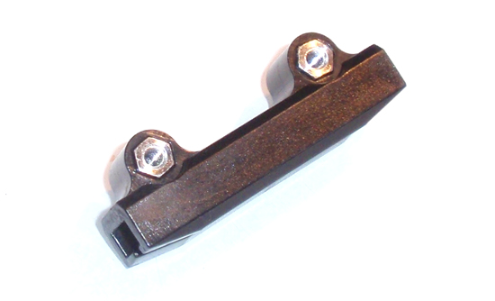
We start the steering rack off by inserting the aluminum tubes into the steering rack holder. They are not a tight fit so make sure they stay keyed to the plastic piece through assembly.
Step 2
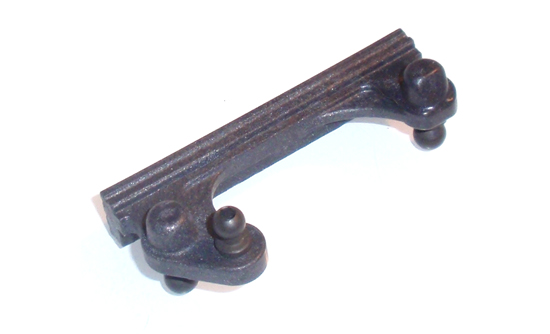
Attach the 3 ball ends to the steering rack. The single ball end on top requires a locknut on the bottom.
Step 3
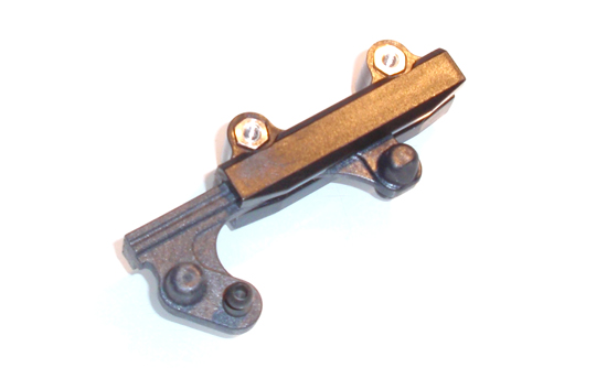
Slide the rack into the holder as shown…
Step 4
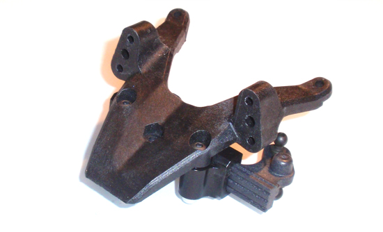
…and attach the steering system to the top plate. Again, make sure the two aluminum pieces are keyed to the steering rack holder.
Step 5
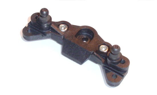
Attach a pair of ball ends (and spacers) to the camber block. Press the pair of locknuts into place as well. These are a press fit so they shouldn’t give you any trouble during assembly.
Step 6
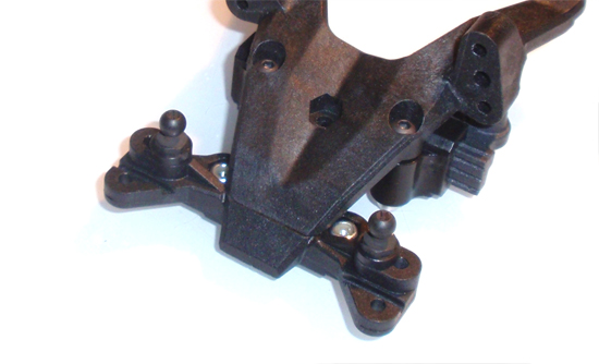
Attach the camber block to the top plate.
Step 7
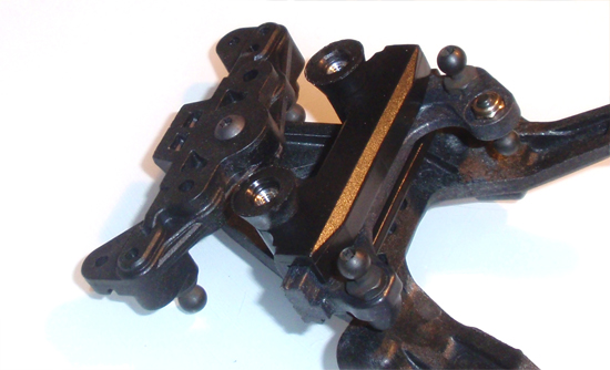
Press the pair of conical spacers onto the aluminum posts from Step 1.
Step 8
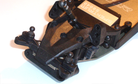
Flip the servo drag link to face up, set the lower bulkhead into position under the chassis and drop the top plate assembly as shown. Moving the drag link up allows us to get a handle on it for the next step.
Step 9
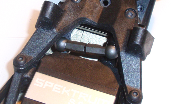
Finally, pop the drag link onto the steering rack.
TLR 22SCT Online Build – Part 3
The front suspension is up next, which includes turnbuckles, suspension arms, the shock tower and front bumper.
Build Notes:
• You’ll be building turnbuckles in this step…never any fun. Have a few rags around to hold the ballcups or, if you have some, grab your ballcup holding tool.
Step 1
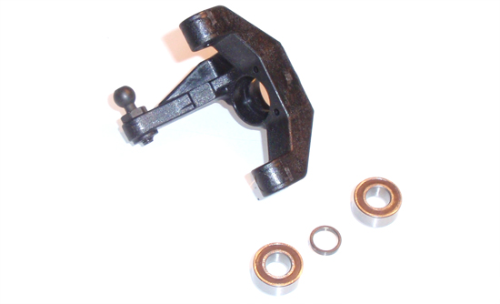
Part 3 of our TLR 22SCT build begins with the steering blocks. Start by installing the ball end into the block (note orientation), followed by the two bearings and crush washer. Make sure the crush washer is seated correctly between the two bearings or the bearings won’t sit flush.
Step 2
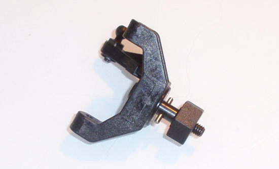
Slide the axle through the steering block, insert the roll pin and slide the wheel hex into place. It’s a pretty tight fit so there is no worry about the pin falling out.
Step 3
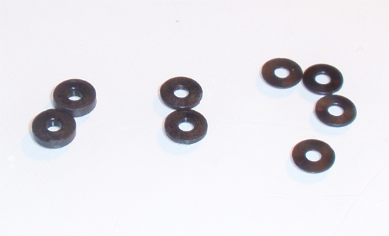
Losi provides 3 different sizes of washers for upcoming steps. As you can see, there are 2 thick washers (2mm), 2 thinner washer (1mm) and 4 thinnest washers (.5mm). For the next step we’ll want to use the 2 2mm washers. Keep the others, however, for tuning the front steering block height.
Step 4
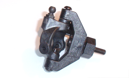
Screw a ball stud into the caster block, then mate the caster block and steering block as shown. Lock the two together with the shouldered screws. Don’t forget to add the 2mm shim above the caster block.
Step 5
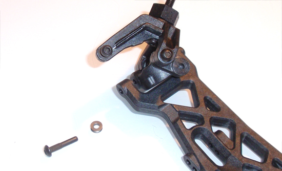
Take a front suspension arm and attach your caster block/steering block assembly to it. The washer shown is a small, metal ‘ringed’ washer. Note the orientation of the front suspension arm, also noting that it will have a slight ‘kick-up’.
Step 6
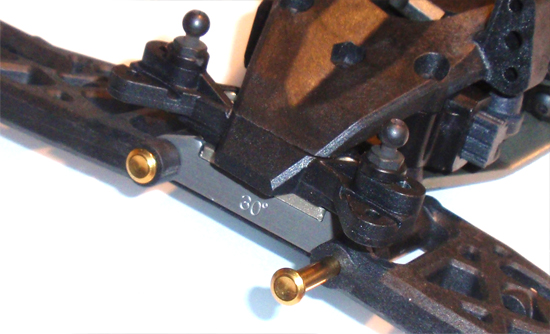
Take both front suspension arm assemblies and attach them to your chassis assembly as shown. The pins will push into place…
Step 7
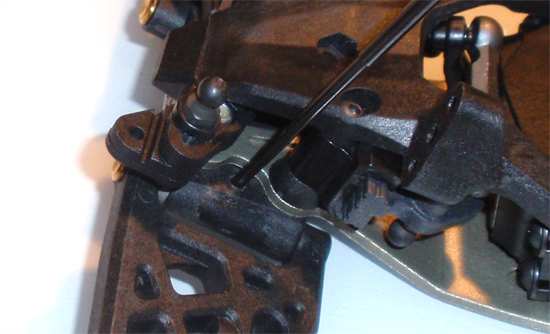
…however you’ll need to lock them in place with the supplied setscrew. Tighten lightly until you feel it ‘drop’ into the cutout in the suspension pin. Do not overtighten.
Step 8
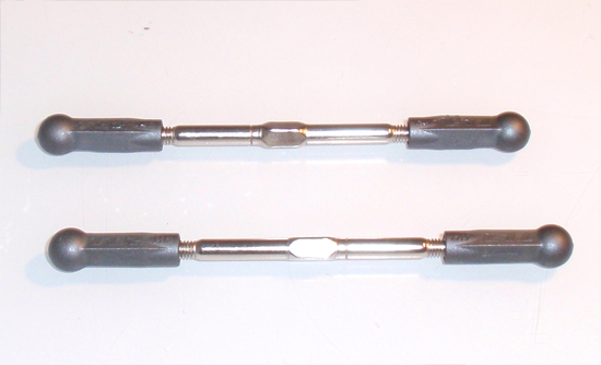
Build 2 camber turnbuckles as shown. The length of 91.2 is a good starting point.
Step 9
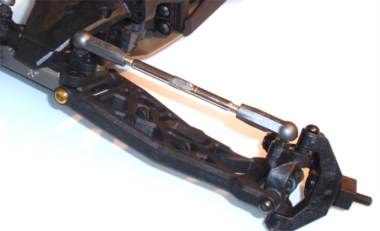
Make sure you have both turnbuckles ‘facing’ the same direction and snap them into place. You can tell which direction they are facing by the little ‘line’ cut into them just off-center of the adjustment square.
Step 10
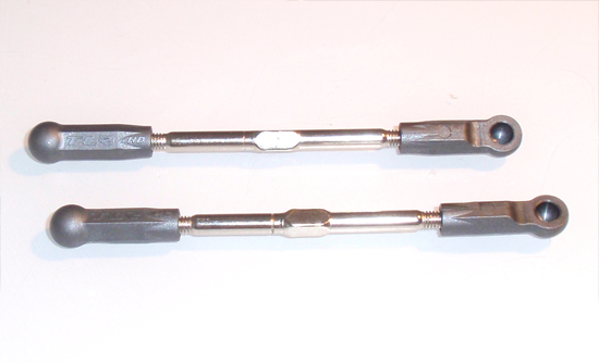
Build 2 steering turnbuckles as shown. The length of 91.75 is a good starting point.
Step 11
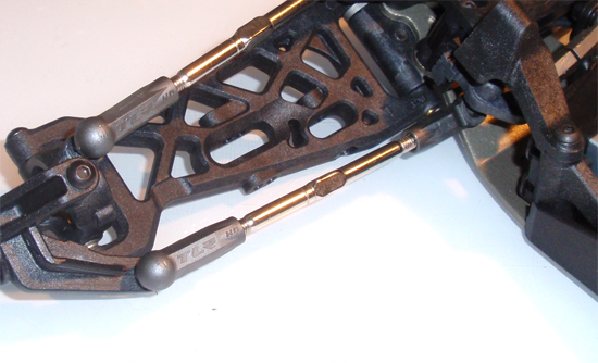
As in Build Step 25, make sure they are facing the same direction (as well as the same direction of the camber turnbuckles) and snap them into place as shown.
Step 12
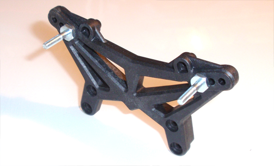
Build the front shock tower. Note the orientation of the tower and the shock mounts.
Step 13
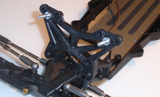
Attach the tower to the chassis assembly.
Step 14
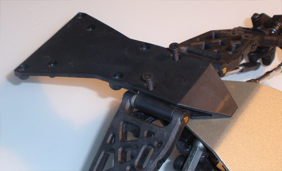
Flip the 22SCT over and install the front skid plate. It’s best to key the skid plate to the chassis first, then screw it into place.
Step 15
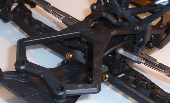
Attach the front bumper brace.
Step 16
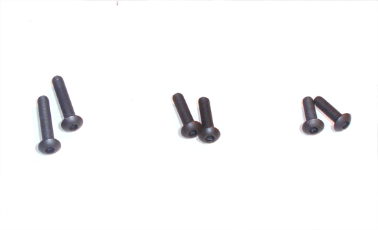
To complete the front bumper, we’ll need to use 3 different length screws; a long (16mm), a medium (12mm) and a short length (10mm).
Step 17
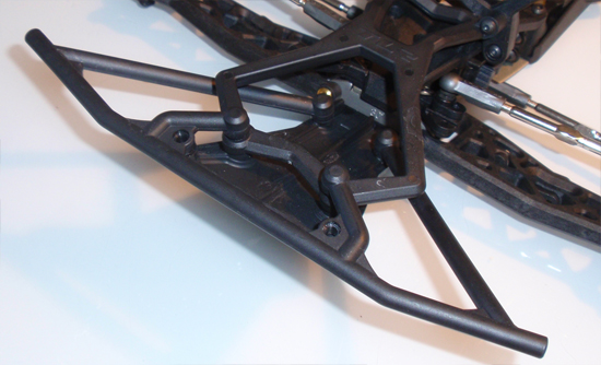
Place the front bumper into place and secure with the 16mm and 10mm screws (the 10mm towards the back).
Step 18
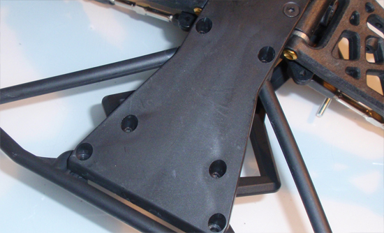
Here is a secondary shot of the bumper attachment. The front holes are empty, the middle holes are where the 16mm screws go and the back holes are for the 10mm screws.
Step 19
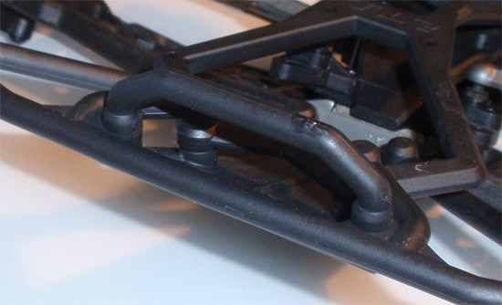
Finally, attach the upper part of the front bumper with the 12mm screws.
TLR 22SCT Online Build – Part 4
Part 4 of the TLR 22SCT build includes the rear suspension and rear shock tower. Carry on.
Build Notes:
• Since you’ll be building the rear drive shafts in this step, you’ll want to make sure to have some clean rags around to clean up any spare grease.
• You will need a few dabs of threadlocking compound during these steps. It is suggested that you only use a VERY little dab at a time.
Step 1
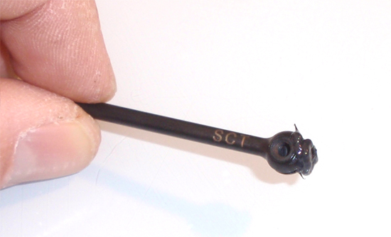
We start off Part 4 by building both rear drive shafts. Insert the barrel into the shaft as shown and apply a liberal amount of black grease.
Step 2
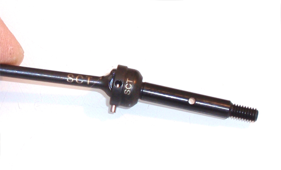
Slide the axle into place followed by the drive pin. This pin should slip through both the axle and barrel (from Step 36) and sit flush in the middle of the assembly.
Step 3
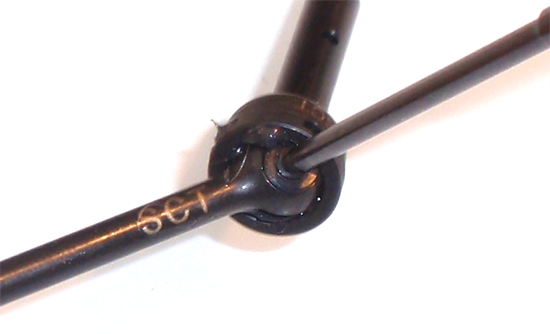
Screw the set screw in as shown, pinning the drive pin in place. A drop of threadlocking compound is suggested here.
Step 4
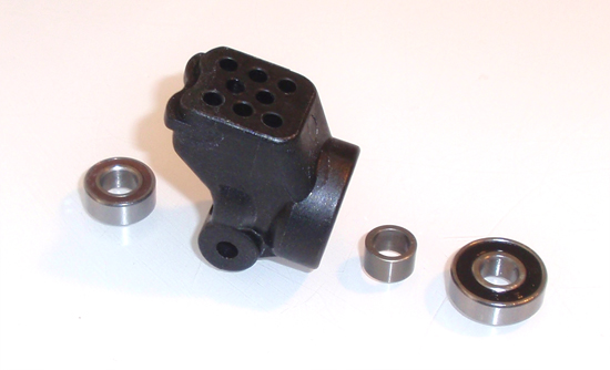
Insert the bearings into the rear hub carrier. Make sure you seat the crush washer between them.
Step 5
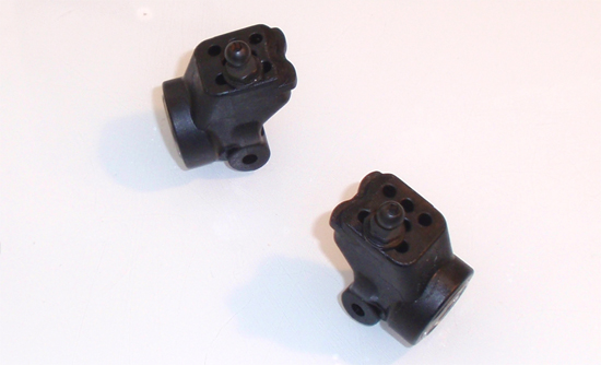
Insert a ball stud into the holes shown. Both hub carriers are the same so you don’t have to worry about a left and right.
Step 6
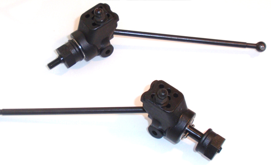
Slide the rear drive shaft assembly through the hub carriers, keeping them in place with the drive pin. Slide the wheel hexes onto the axles and, while lining up the pins and grooves, push the hexes all the way into place.
Step 7
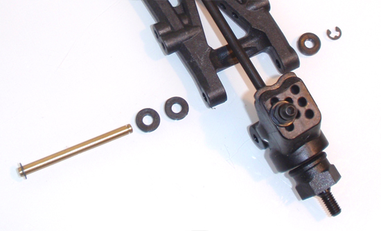
Slide an e-clip onto the hinge pin and attach your rear hub carrier assembly to the rear suspension arms. Note the spacers; there are two 2 1mm spacers to the front and 1 2mm spacer to the rear.
Step 8
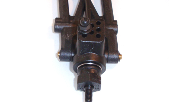
A side view of your assembly. Note the longer ‘nubs’ on the suspension arm near the top of the picture. They should be facing forward, or on the same side as the ball stud (in the rear hub).
Step 9
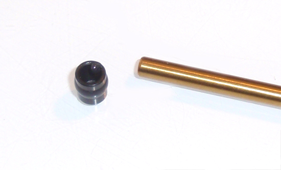
Apply a very small dab of grease to the hinge pin cup (as shown) and slide onto the inner hinge pin. I’ve done this to keep the hinge pin cup in place during the next couple steps.
Step 10
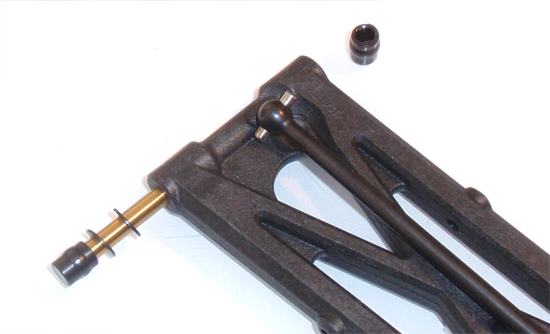
Slide the hinge pin assembly through a pair of 0.5mm spacers, then through the suspension arm. Apply another little drop of grease to a second hinge pin cup and slide it on the hinge pin.
Step 11
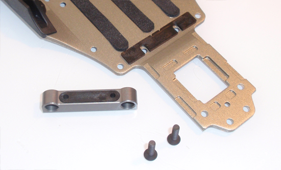
Press the plastic toe block insert into the aluminum housing. Insert the screws through the bottom of the chassis and attach the hinge pin block (only screw in about 2-3 turns. Slide the 2 degree shim between the aluminum toe block insert and the chassis and tighten down the screws. Make sure the insert stays square with the assembly.
Step 12
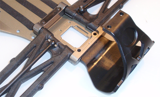
Slide the two suspension arm assemblies into place as shown and capture with the rear aluminu toe block. Slide the tab from the rear motor guard into the slot (between the chassis and rear toe plate) and, using the M2x6mm screw, secure the assembly. Do not overtighten.
Step 13
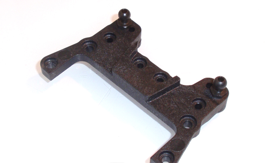
Insert two ball studs into the rear camber block as shown.
Step 14
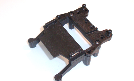
Attach the camber block to the rear battery capture tray…
Step 15
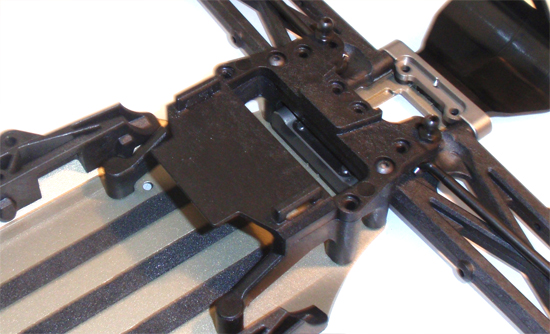
…and attach that assembly to the chassis as shown.
Step 16
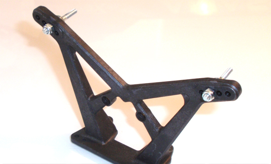
Attach the upper shock mounts to the rear shock tower using the holes per the manual. Note the direction of the tower.
Step 17
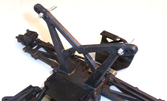
Attach the tower to the chassis.
Step 18
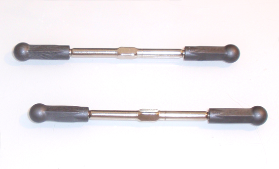
Build a pair of rear camber links as shown. Then length of 92mm is a good starting point.
Step 19
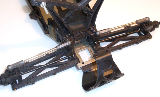
Pop the rear camber link into place as shown.
TLR 22SCT Online Build – Part 5
In Part 5, I’ll be assembling the transmission of the TLR 22SCT. Although we have the option to build it as a MM (Mid Motor), I’ve opted to build it as a RM (Rear Motor) layout. That’s the most popular at my local track.
Build Notes:
• I’ll be working with greases to build the differential. Get some paper towels to help keep things clean.
• The slipper pads fit into grooves on the spur gear. The fit is not tight, nor do they ‘snap’ into position, so be careful during this part of the assembly that they don’t fall out of the grooves
Step 1
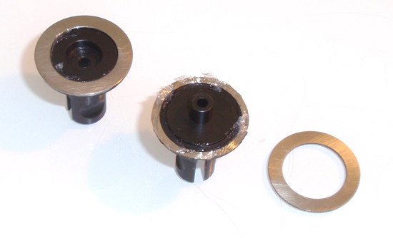
The first step is to build the differential. Put a dab of grease on the outdrives and then seat the rings in place. The grease helps keep the rings attached to the outdrives.
Step 2

Slide a thrust washer over the thrust screw and apply a liberal amount of black grease…
Step 3
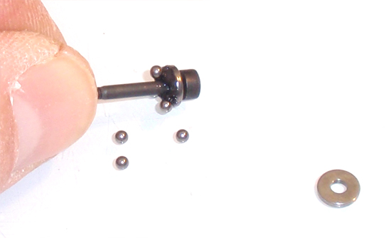
…and ‘roll’ it over the small, 2mm balls to ‘pick them up’.
Step 4
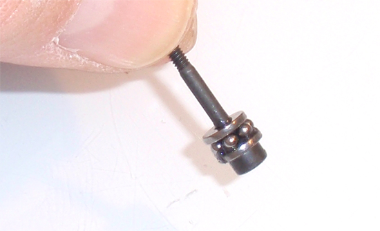
Make sure the balls seat flat against the thrust washer. Now slide the 2nd thrust washer over the assembly.
Step 5
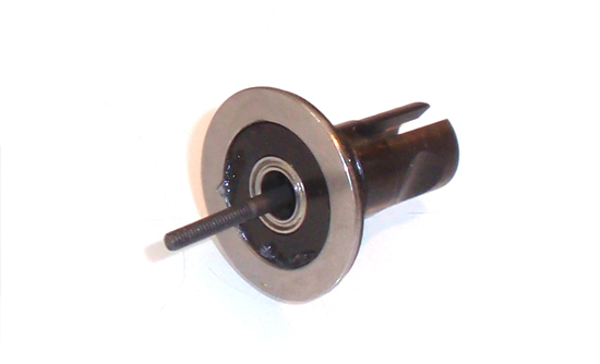
Insert a 5×8 bearing into the ‘female’ diff housing, then slide the thrust washer assembly into place as shown.
Step 6
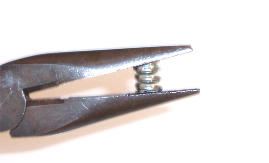
It’s always a good idea to pre-compress any springs. Do this with the diff spring prior to installation.
Step 7
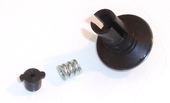
Drop the spring into the ‘male’ diff half followed by the diff nut housing.
Step 8
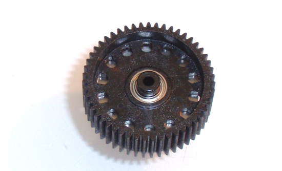
Slide the 5×8 bearing onto the ‘male’ diff housing followed by the diff gear.
Step 9
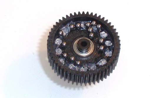
Fill the diff ball holes with clear grease. Drop the 14 diff balls onto the diff gear as shown…
Step 10
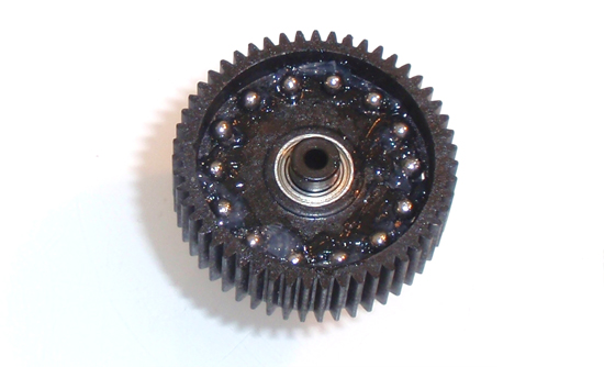
…and move into position, pressing them down into the holes.
Step 11
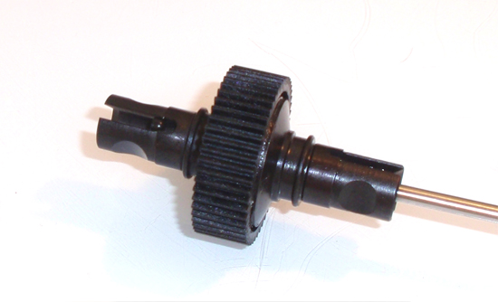
Slide the two diff assemblies together and tighten the diff thrust screw. Tighten down until it bottoms out, working the diff every turn or two. Once bottomed out, back it off approximately 1/8 of a turn. It should feel nice and smooth.
Step 12
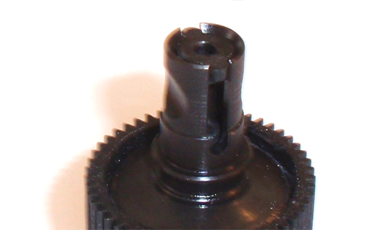
Slide the diff thrust nut protecting piece into place.
Step 13
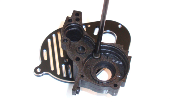
Attach the transmission case half to the motor plate with the single screw as shown. Add a small dab of threadlock here.
Step 14
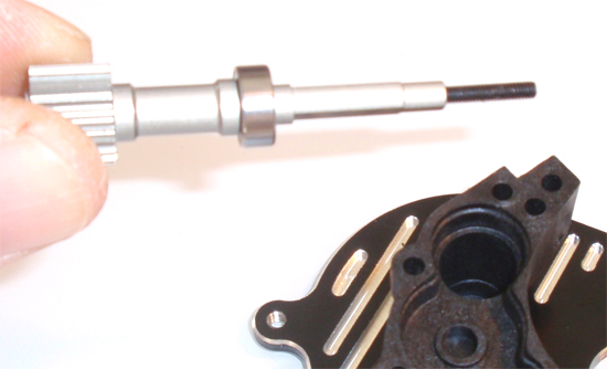
Slide a 5×10 bearing onto the top shaft and insert that assembly into the transmission case.
Step 15
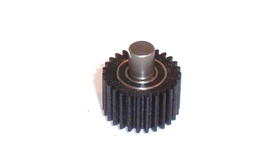
Assembly the idler gear with two 5×10 bearings as shown.
Step 16
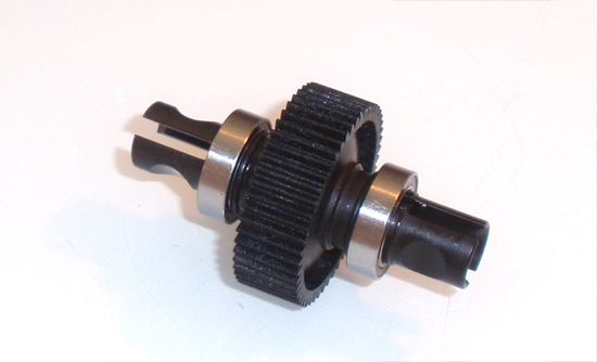
Slide a pair of 10×15 bearings on to each side of the differential.
Step 17
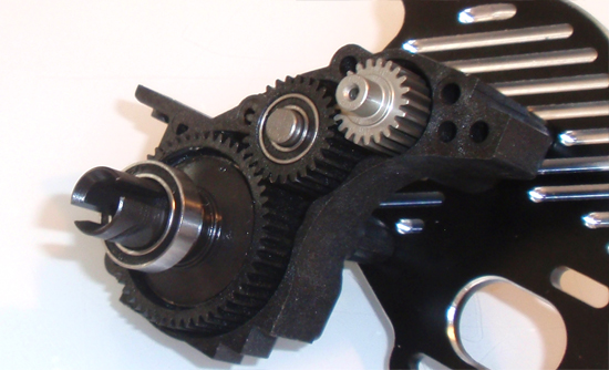
Slide the idler gear assembly into place followed by the differential. Make sure the diff thrust screw is facing AWAY from the motor plate.
Step 18
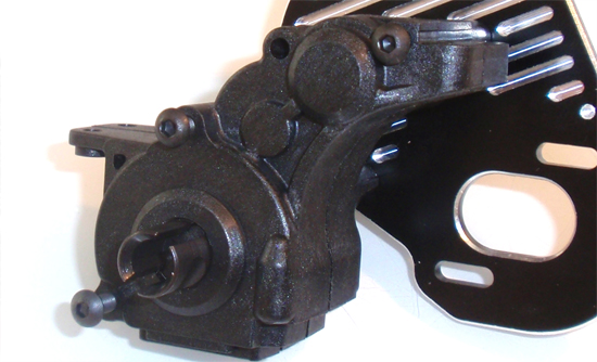
Slide the opposite transmission case half into place and secure with the three screws (1 3×16, 1 3×35, 1 3×40). A small drop of threadlock on the two longer screws will help keep them from backing out.
Step 19
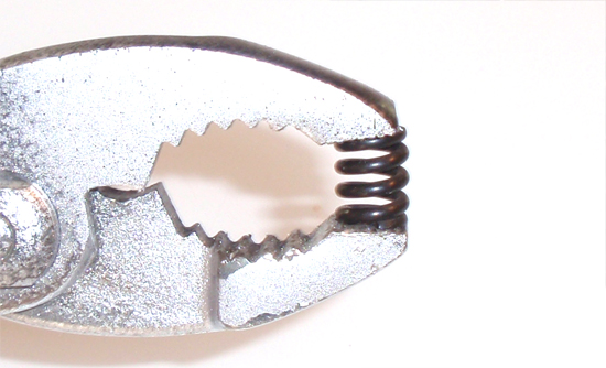
Pre-compress the slipper spring.
Step 20
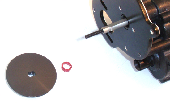
Slide the red washer onto the top shaft followed by a slipper plate. Both plates are the same and feature a flat spot to key to the top shaft.
Step 21
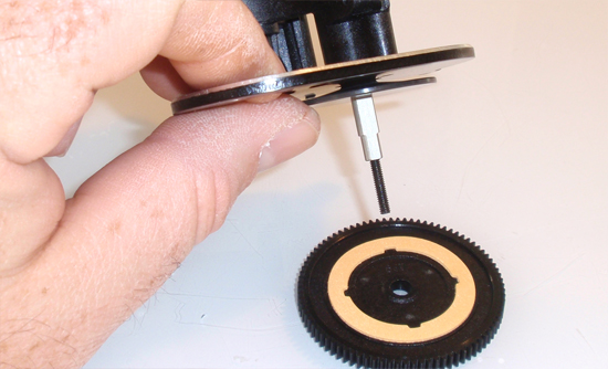
Press a slipper pad into the grooves of the spur gear. Slide the gear assembly onto the top shaft. I found it easiest to face the top shaft down (as shown) to make sure the pad stays in the grooves on the gear during assembly.
Step 22
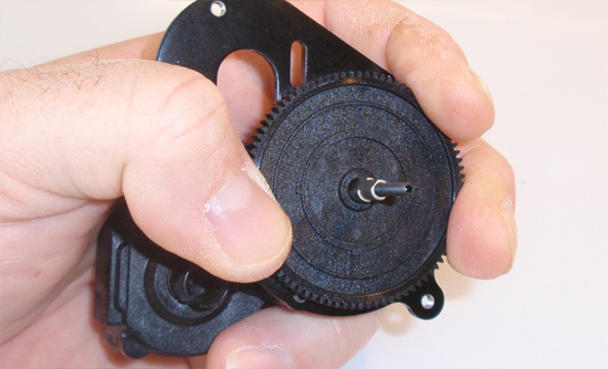
While holding the spur gear assembly tight (making sure the pad doesn’t fall out of the grooves in the gear)…
Step 23
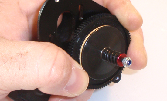
…slide the second slipper pad, second slipper plate, slipper spring, slipper washer and slipper nut into place.
Step 24
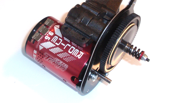
Tighten down, making sure the slipper pads stay in the grooves of the gear. I tighten down quite a bit; final adjustment will need to be done at the track. You can also attach your motor and pinion gear at this time.
Step 25
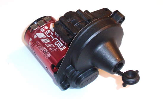
Attach the gear cover, followed by the slipper adjustment plug.
TLR 22SCT Online Build – Part 6
The next step in our TLR 22SCT build is attaching the transmission and rear bumper to the chassis assembly. Again, we are building the 22SCT in the RR (Rear Motor) design so your steps for MM (Mid Motor) will be different.
Build Notes:
• The instructions tell you to install the rear body mount prior to installing the upper rear bumper brace. I’ve switched this around a bit to make it easier (and keep the cussing to a minimum).
Step 1
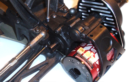
Start off this step by sliding the transmission assembly into the chassis as shown. It may take a little wiggling but it does fit in quite easily. You might also want to slip the drive bones into the outdrives…as you can see I didn’t do that. Secure in place with 2 screws up top and 2 in the bottom.
Step 2
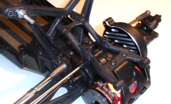
Attach the rear tower/rear bumper support brace.
Step 3
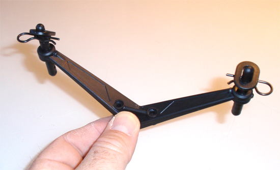
The next couple of steps are going to be a bit out of order simple because they won’t work as it shows…and you’ll see why. First, assemble the rear body mount as shown…
Step 4
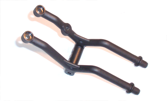
…as well as the upper rear bumper brace.
Step 5
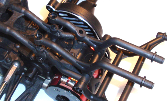
Attach the upper rear bumper brace at the swivel point…
Step 6
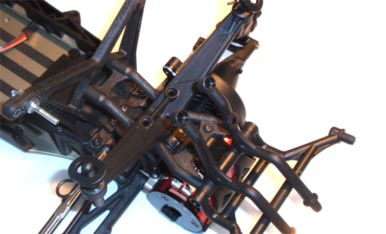
…and rotate them up and out of the way. Place the rear body mount into place, swivel the upper rear bumper brace back into place and secure with the 2 3x18mm screws. Since the rear body mount does not ‘snap’ into place, installing it before the upper rear bumper brace only results in the rear body mount falling all over the place.
Step 7
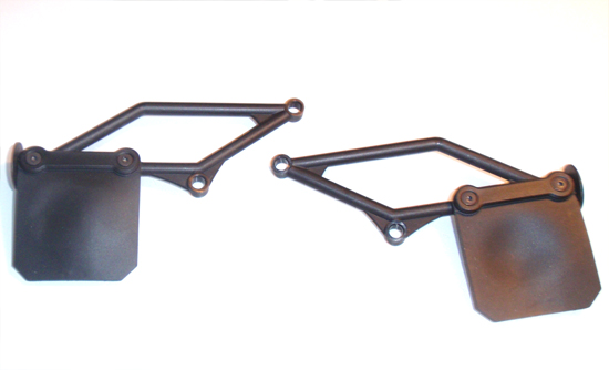
Assemble the mud flaps…
Step 8
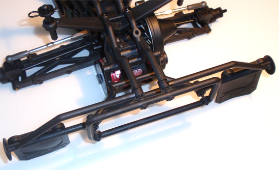
…and bolt them to the rear bumper. You can build the 22SCT with an optional ‘narrow’ rear bumper to eliminates the mud flaps (and mud flap hangers), but I prefer to use them and help protect the body.
TLR 22SCT Online Build – Part 7
The shocks (or dampers) on any car, onroad or off, are probably the most important, and overlooked, parts of the car. Built correctly, they will give you a distinct advantage over those that don’t take the extra time to do so. Take your time here and do it right.
Build Notes:
• Shock builds mean potentially messy oil spills, so make sure you are doing this step on a clean, covered surface. Have plenty of rags (or towels) around should you spill any oil.
• I also suggest you have some sort of shock stand to set them oil-filled shocks while working. I have been using the Duratrax Pit Tech Deluxe Shock Stand and absolutely love it.
Step 1
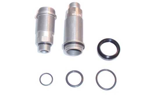
Before we begin, let’s get a little better aquainted with the external shock o-rings. As you can see, there are 3 different sizes; small, medium and large. The small one goes on the bottom part of the shock (as shown) while the medium one goes on the top. The largest one gets fed into the pre-load adjustment nut.
Step 2
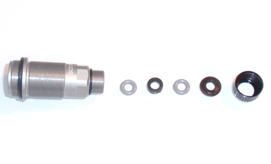
Now that you’ve had your o-ring lesson, let’s start this step by installing the 4 small, external shock o-rings and the 4 medium, external shock o-rings onto all 4 bodies. Once that’s done, build the internal shock cartridge as shown: small, internal o-ring, spacer, small, internal o-ring and the cap spacer. Screw the lower shock cap on, making sure all the parts stay seated and squared up in the cartridge.
Step 3
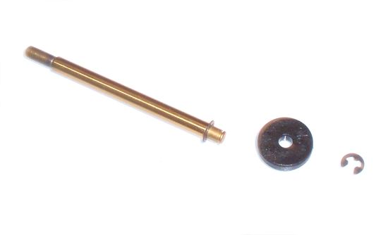
Build 4 shock shafts by installing an e-clip, piston and another e-clip. Note that the front shafts are shorter than the rears and use a #57 piston. The rear shocks use the #55 piston (and attach to the longer shafts).
Step 4
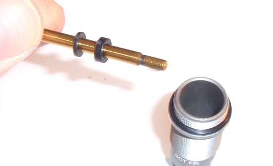
Slide 1 1mm and 1 2mm spacer onto each shaft (both front and rear). Coat the threads of the shaft with a drop or two of shock oil and feed the assembly down into the shock. You want to lightly push it through the lower cartridge so you don’t rip the o-rings. If you feel any resistance, stop and make sure all the parts in the cartridge area are correctly installed.
Step 5
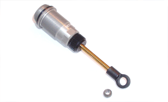
Once the shafts are in the bodies, install the pivot ball cup on the bottom as shown. Press one of the pivot balls into cup. This might be a little difficult, so place the assembly on a table to make it easier to push into place.
Step 6
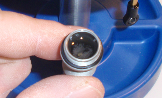
Fill one shock with oil and gently slide the shock shaft up and down. This will release any air bubbles below the piston. You should see a bunch of bubbles floating to the top; place this shock onto your shock stand and repeat with the other 3 shocks.
Step 7
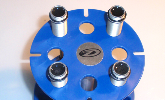
Take a little break as the bubbles float to the top. This is a good time to get a drink, donut or do 50 pushups (10 if you’re out of shape).
Step 8
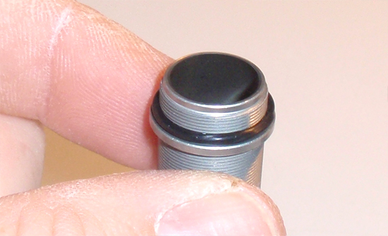
Once the bubbles have disappeared, fill the shock up so that the oil crowns the top (as shown).
Step 9
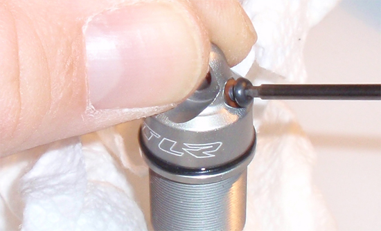
Slowly screw the shock cap on so you don’t spill any oil. Take the bleeder screw, install a small, red o-ring onto it, and screw it into the bleeder hole on the cap (not all the way…just a couple turns). Press the shaft all the way into the body (or a little less if you want a little more pack) and let the oil ooze out of the bleeder hole (you might need to back the screw off a tiny bit for this to happen). Once you’ve ‘bled’ the shocks, tighten the bleeder screw down. Do the same thing with the 3 other shocks, making sure you bleed out the same amount of oil in all 4 shocks.
Step 10
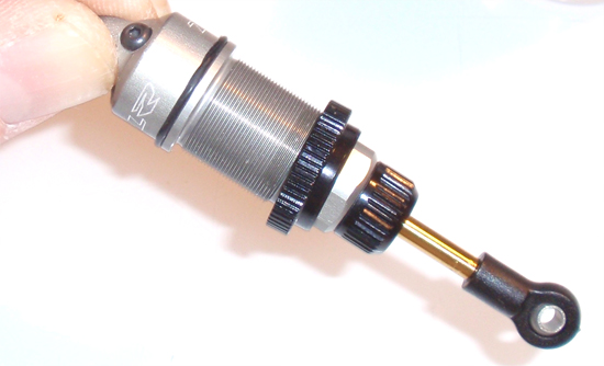
Install the large o-ring into the pre-load adjustment nut. Feed this assembly onto the body and screw all the way to the top.
Step 11
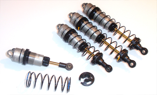
Slide the springs onto the shocks (short spring, front shock; longer spring, rear shock) and snap a lower shock retainer into place.
Step 12
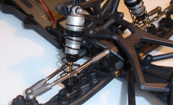
Install the front shocks as shown. It’s easiest if you slide the top on (but don’t fasten) and completely attach the bottom first.
Step 13
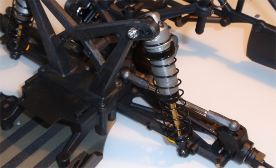
Install the rear shocks as shown.
TLR 22SCT Online Build – Part 8
Part 8 is a short step; we’re basically bolting on the miscellaneous chassis bits prior to final assembly. Pretty easy.
Build Notes:
• None.
Step 1
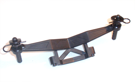
Start off by sliding the body posts down into the front body mount and pin them in place with the 12mm screw. Slide the swivel mounts over the posts and secure with the body clips. You can follow the manual for the initial step, but some adjustment may be required after installing the body. Attach to the front tower, making sure the ‘V’ shape in the mount is facing the front of the truck.
Step 2
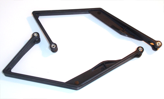
Push a M3 locknut into the side bumper as shown. Make sure they seat all the way down and are straight; if not, you could cross-thread them.
Step 3
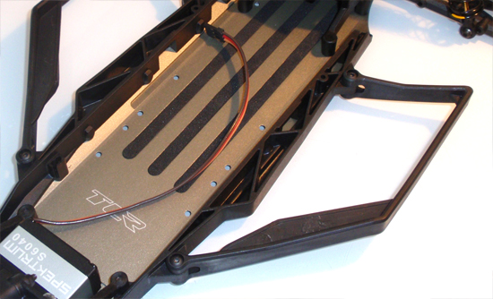
Flip the side bumpers over and attach to the chassis. Do not overtighten, just snug down.
Step 4
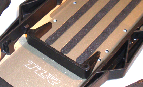
Attach the battery tray. Multiple mounting positions are included depending on what battery you are running (long or short).
TLR 22SCT Online Build – Part 9
Part 9 is a set of short steps as well. We’re installing the electronics, however the manual doesn’t go into detail about where to mount the ESC or receiver. I’m installing them in the most common locations but this is really up to you.
Build Notes:
• None.
Step 1
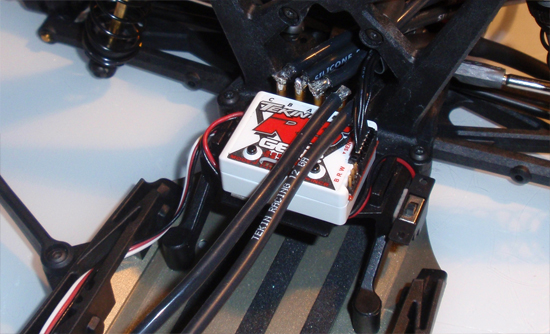
The ESC typically mounts on the little tab on the rear bulkhead. Even though the tab is a bit small, most ESC’s should fit on here without any problems. I wired mine so the motor wires feed right through the rear tower and straight to the motor. The sensor wire also fallows this route. It’s hard to see, but the capacitor is routed right to the back of the ESC.
Step 2
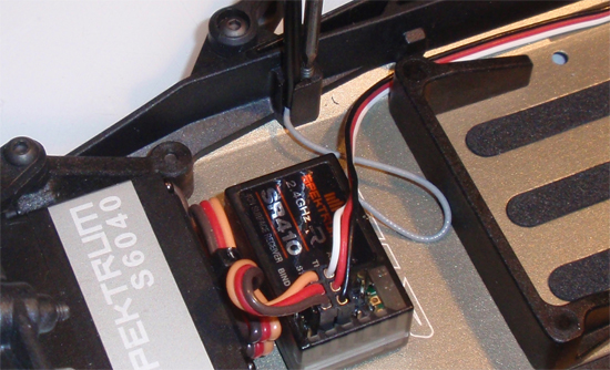
The receiver sits right behind the servo. If you plan on racing, you can mount it off to the side a bit so you can fit a transponder.
Step 3
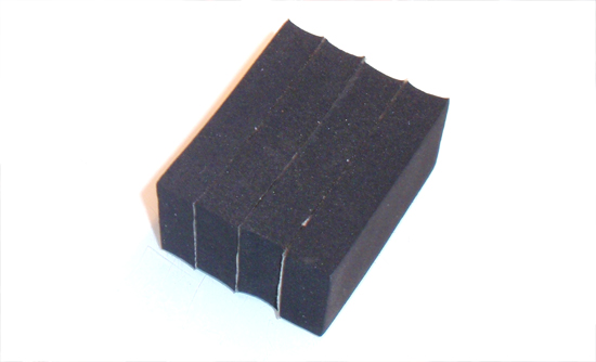
TLR provides a 4-pack of foam blocks, allowing you to shift the weight of the battery around. Since most of the team runs the battery full forward, I stuck them all together. This was actually a suggested step much earlier in the manual, but I didn’t want to have to deal with the foam blocks moving around while I was assembling the rear of the truck.
Step 4
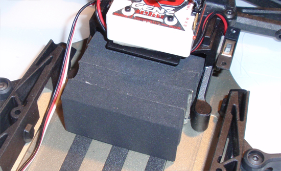
Slide the foam block assembly into the rear bulkhead.
Step 5
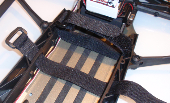
Finally, insert and battery straps as shown. When installing a battery, you can slide it under the entire strap or through the center (as seen with the rear strap).
TLR 22SCT Online Build – Part 10
In Part 10 we finish up our Losi 22SCT build; the body, the wheels and the tires. Four quick steps…let’s get to it!
Build Notes:
• You’ll be using CA glue to bond the tires to the wheels. Be VERY careful with this glue; it bonds fingers to objects just as well as it does the tires!
• The 22SCT doesnt’ come with tires simply because Losi isn’t sure where you’ll be running your truck. Letting you choose your own tires helps keep the cost of the truck down (since you may never use the tires they provide anyway).
Step 1
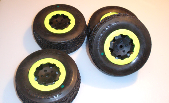
For rubber, I went with AKA Handlebar tires all the way around. These should work great on the surface I’m running on. I also chose to use the beadlock style rings instead of the dish covers. I do like the dish covers more, but I’m dying them red to match the truck.
Step 2
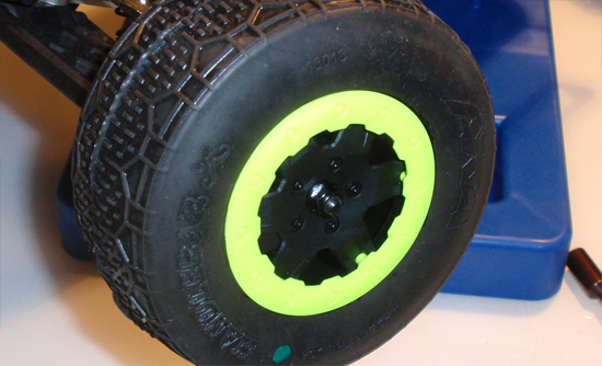
After mounting the tires (see my Tire Mounting How To), slide the front tires onto the axles and secure with the 7mm locknut.
Step 3
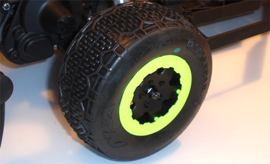
Follow the same instructions as above for the rear tires.
Step 4
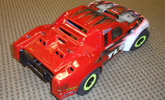
Finally, paint your body and mount it up. Use the 4 body clips to secure. You can raise and lower the body by raising or lowering the body mount posts. For those of you that like to cut the body out (to keep air flowing through it), you can see I did that on this Proline body (see my How to Prep a Short Course Body).
That’s it, you’re done! Now get your 22SCT out to the track and show the competition what’s up!

