

Team Associated Factory Team T4.2 Online Build
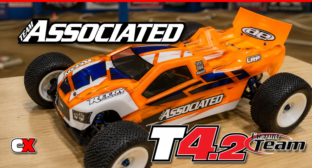
Team Associated has added the Factory Team treatment to their T4.2 offroad stadium truck. Adding features like their 12mm Big Bore shocks, VTS Slipper unit and a Proline Bulldog body, this truck is a hit right out of the gate. So for this article we get to build the T4.2 up with all the cool goodies AE has to offer.
Follow our step-by-step build up right here on CompetitionX. Testing and my final thoughts will be posted in an upcoming review.
Team Associated Factory Team T4.2 Online Build – Part 1
The steering is typically the first part of almost every build, and the FT T4.2 is no different. It’s simple and straightfoward. Let’s get to it.
Build Notes:
• The instructions show the addition of the little foam dust covers over the ball ends. While I didn’t use them, I would suggest doing so. It does help prolong maintenance.
• You will need a small dab of blue threadlock later in the build. Get it ready now.
Step 1
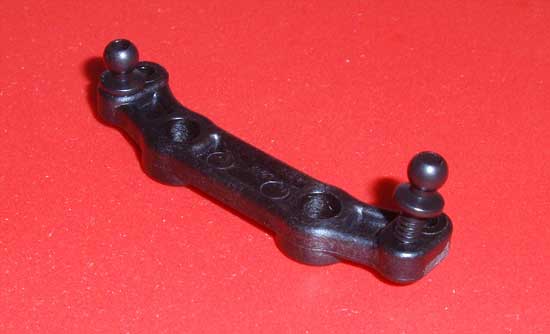
The first step is to screw both black ballstuds into the steering rack. I used the front sent of Ackermann holes per the manual. Moving the ballstuds back will change the Ackermann and the way the T4.2 feels on the track.
Step 2
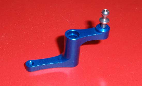
Insert one of the silver ballstuds into the blue, Factory Team bellcrank as shown. A very light dab of blue threadlock will help keep the ballstud from backing out.
Step 3
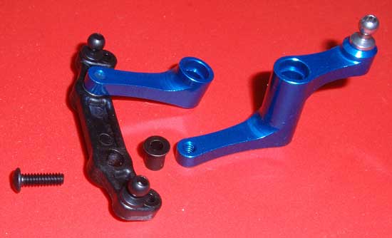
Slide both ‘tophat’ bushings into the steering rack from the top. Attach each of the bellcranks to the steering rack with the 4-40×3/8 screw. You’ll want to add a dab of blue threadlock to these screws. Do not use too much or you could lock the screw to the tophat bushing.
Step 4
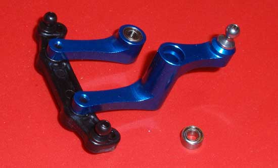
Insert the steering rack bearings into position. There will be one on the top and bottom of both bellcranks.
Step 5
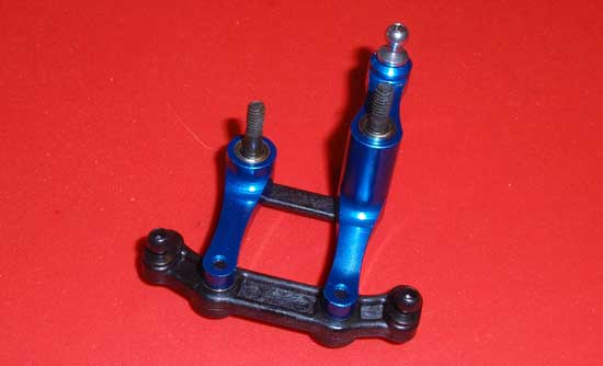
Take your steering bolts and slide them through the steering brace, then up through the bellcranks. Keep in mind that the steering bolts are different lengths; the long one will go through the taller bellcrank.
Step 6
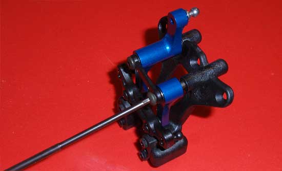
Slide the assembled steering unit into place on the top plate and tighten both screws down. You want to tighten them down enough that there isn’t any play, but not to tight that it binds the steering movement.
Step 7
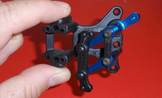
Time for the ‘free-movement’ test. Hold the new steering assembly on its side, swing the steering rack to the top and let go. Does the rack fall quickly to the bottom? If so, you’ve passed the ‘free-movement’ test. If not, loosen the two steering bolts SLIGHTLY and try the test again. The easier it moves, the less work your servo will have to do.
Step 8
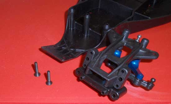
Align the front bulkhead with the bottom of the top plate and press into place. Note the direction of the front bulkhead; the two molded ‘pins’ should face forward. Now attach this assembly to the chassis (using the back two holes) using the 4-40×5/8 screws.
Step 9
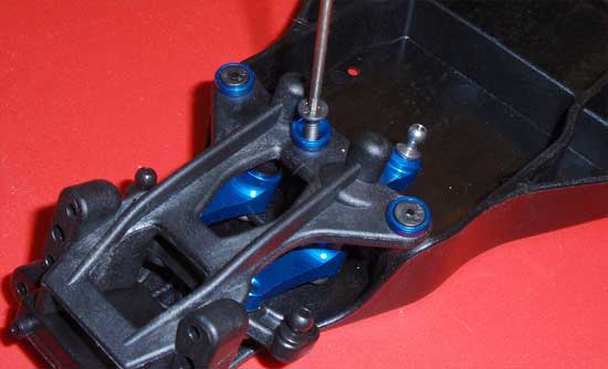
The final step is to secure the top plate to the chassis using the 4-40×1/2 screws. Don’t forget to use the cool Factory Team countersunk washers!
Team Associated Factory Team T4.2 Online Build – Part 2
The front suspension of the Factory Team T4.2 is similar to the rest of the B/T series; dual bellcrank, long, ‘gull-wing’ suspension arms and adjustable camber, caster, toe and roll centers. The FT T4.2 does away with the older bearing-on-axle front hubs and instead moves to the more acceptable, clamping-style hexes.
Build Notes:
• The caster and steering blocks are directional to pay attention as to which side you are mounting them. The steering blocks are marked with a R and L, however the caster blocks are not.
• You’ll need thread-locking material during this step as well.
Step 1
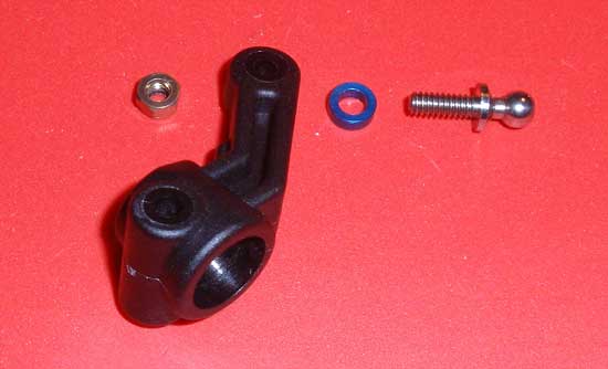
The first step is to build a pair of front steering knuckles. Slide one of the Factory Team aluminum washers onto a silver ballstud and attach it to the knuckles. Secure it on the bottom with an aluminum locknut. The locknut recesses into the bottom of the knuckle, so be sure it is seated correctly before tightening it down. Build 2 of these.
Step 2
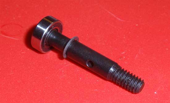
Slide one of the 5/16×3/8 bearings all the way onto the front axle. Take the 3/16 C-Clip and snap it into the groove on the axle as shown. It may take a bit of force, so I would suggest using a pair of needlenose pliers to seat it all the way into the groove. Build 2 of these.
Step 3
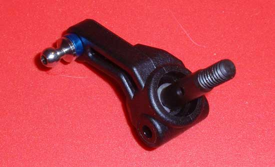
Slide the axle assembly into the knuckle from the back side as shown. Build 2 of these.
Step 4
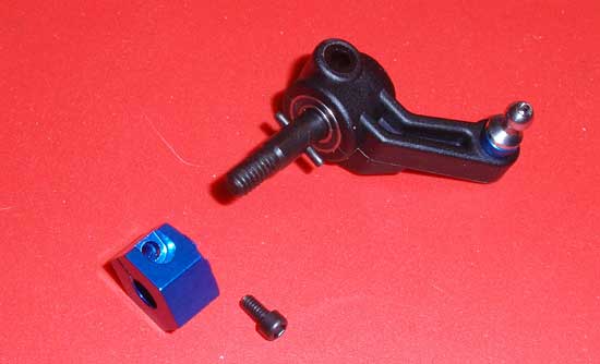
Press the 2nd 3/16×3/8 bearing into the knuckle. Again, using a pair of needlenose pliers (or even channel-locks), press the univeral roll pin through the hole in the front axle. You’ll want to center it to the axle as shown. Slide the FT, 12mm aluminum clamping hex onto the axle and key it to the univeral roll pin. It should slide onto the axle all the way to the bearing. If not, you might need to re-center the univeral roll pin. Once seated, insert the 2-56×3/16 screw into the clamping hex and tighten.
Step 5
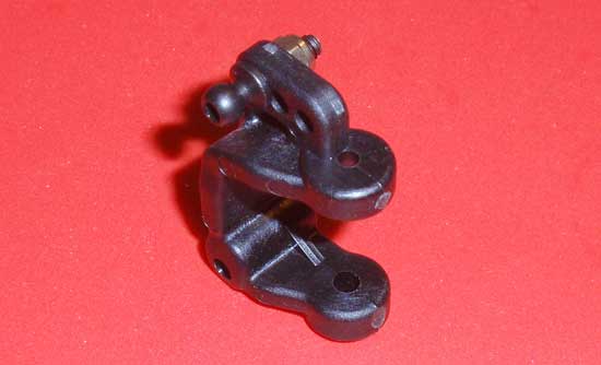
Insert a black ballend into the caster block and secure with the aluminum locknut. Notice the direction (and orientation) of the caster block. The one shown is the left side. Build 2 of these.
Step 6
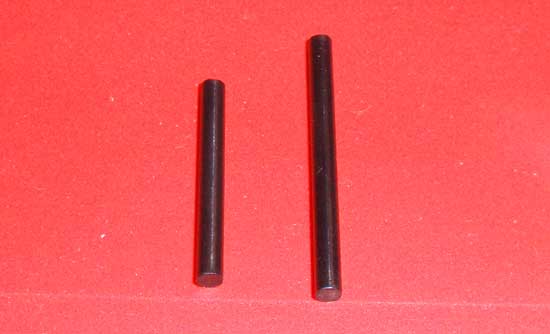
Team Associated supplies 2 different length hinge pins for the outer area of the front end of the Factory Team T4.2; a short and a long. The short one is used as the kingpin, the longer one is used as the hinge pin. Grab the 2 shorter ones for the next step.
Step 7
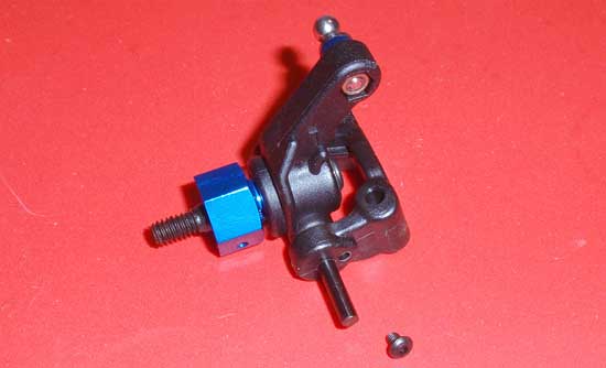
Take the left caster block we built in step 14 as well as the left steering block (marked with the L) and assemble as shown. Use the shorter kingpin and feed it up through the caster and steering block. It should seat with the bottom of the kingpin sitting flush with the bottom of the caster block. Secure in place with the 2-56×1/8 screw. Build both sides…
Step 8
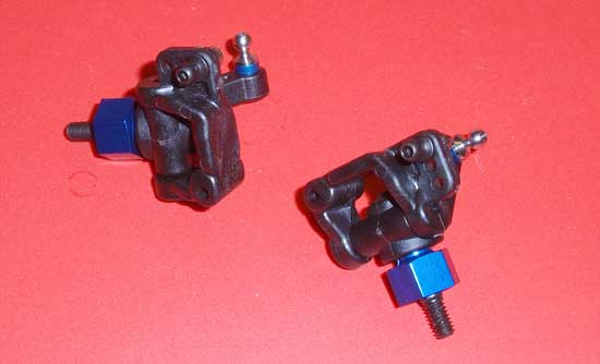
…and match your assemblies up with this picture. Shown is the right side (up top) and the left side (lower right).
Step 9
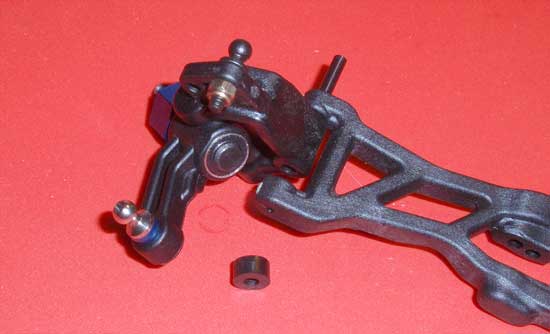
Grab your left steering assembly, the longer hinge pin, the spacer and the left suspension arm and assemble as shown. Make sure you attach the suspension arm with the ‘kink’ up as shown. Build both sides.
Step 10
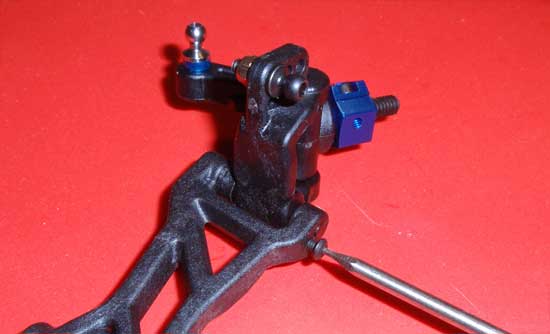
Once assembled, the hinge pin should sit flush with the outside of the arm. Secure in place with the 2-56×3/18 screw.
Step 11
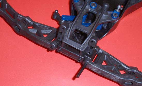
Take both front suspension assemblies and attach them to the front bulkhead with the longest hinge pins as shown. Again, makes sure the arms are ‘kinked’ up and the steering ball link is to the rear of the car.
Step 12
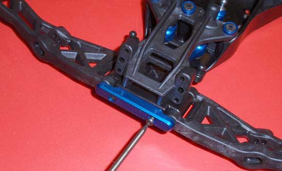
Attach the Factory Team aluminum front hinge pin brace and secure with the 2 2-56×5/16 screws. At this time, you’ll want to make sure the front arms swing up and down without binding.
Step 13
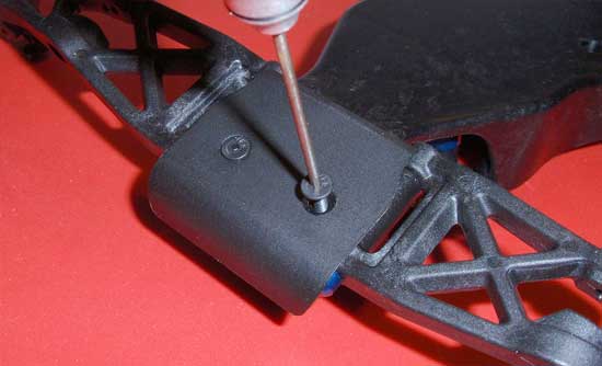
Flip the T4.2 over and attach the front bumper as shown. Easy step.
Step 14
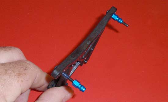
Grab the front shock tower and feed the two 4-40×3/4 screws into the upper shock mounting holes (use the center hole per the instructions). Apply a small drop of blue thread-locker and screw on the Factory Team aluminum shock bushings. Notice, where I’m holding the tower, you see the camber link pads. This will help you orientate which side of the tower the screws go through.
Step 15
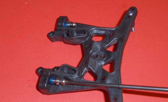
Slide a 2mm Factory Team aluminum washers onto the silver ballstuds and screw them into the inner hole on the camber link pad as shown. DO NOT OVERTIGHTEN or you will strip out the plastic. Snug is fine.
Step 16
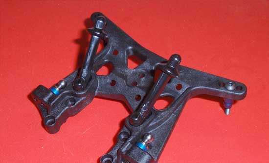
Attach the body mounts to the front tower as shown…
Step 17
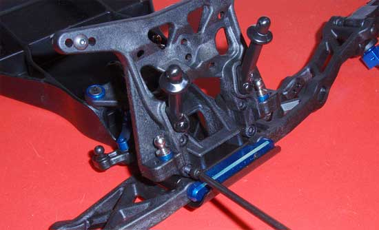
…and attach the tower to the front bulkhead of the T4.2 Again, no need to overtighten. A tick past snug is fine.
Step 18
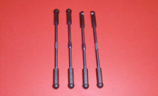
Other than shocks, the turnbuckles are one of my least favorite things to build. Just make sure you use the 2.65″ turnbuckles (the shorter ones) for the camber and the 2.8″ turnbuckles (the longer ones) for the steering. The lengths that AE has posted in the manual (48.75mm for the camber and 52.75mm for the steering) are a good starting point. Also, keep an eye on the ‘notch’ on the center part of the turnbuckle. You’ll want to build the turnbuckles so that the notch will be ‘pointing’ the same direction. Build 2 of each but keep them separated.
Step 19
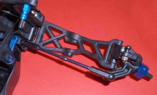
Snap the 2 steering turnbuckles (the longers ones) in place as shown. Make sure the ‘notch’ is pointing the same direction.
Step 20
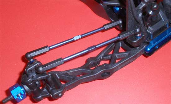
Snap the 2 camber turnbuckles (the shorter ones) in place as shown. Make sure the ‘notch’ is pointing the same direction as the steering turnbuckles.
Team Associated Factory Team T4.2 Online Build – Part 3
Part 3 of this build revolves around the transmission of the T4.2. This is one of the best transmissions out there and is extremely easy to build.
Build Notes:
• Take your time building the differential. This is one of the most important parts to build right as it help provide grip for the rear of the T4.2. It’s also an involved process to remove and fix if you don’t do it right the first time.
• You will be working with greases and lubes in this step so it’s a good idea to have some clean towels or rags handy.
Step 1
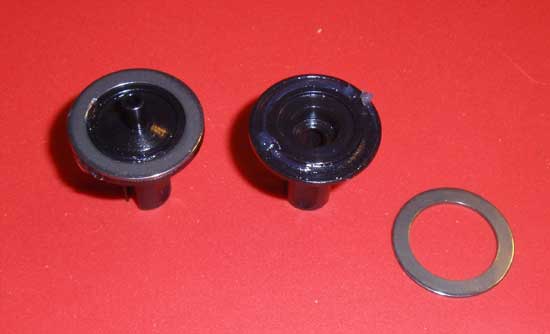
The first thing we need to do is get the diff rings to stay connected to the outdrives. You can do this by applying a bit of the clear diff lube to the outdrive and then attaching the ring to it.
Step 2
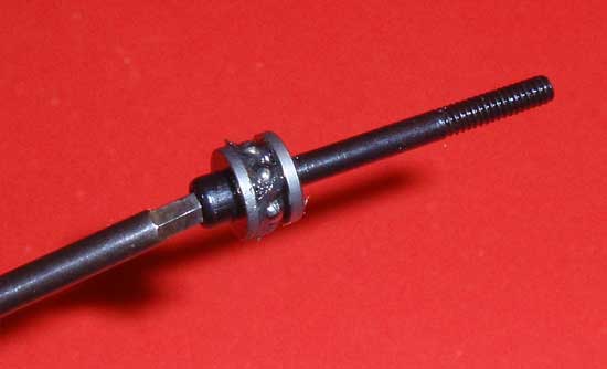
The next step is to build the thrust bearing assembly. Start by sliding one of the diff thrust washers onto the diff thrust bolt. Apply a thin layer of black grease to that washer and carefully place the 6 thrust balls into the grease. Slide the 2nd thrust washer into place. Your assembly should look like this. You might run your finger around the outside to remove any excess grease.
Step 3
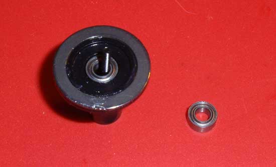
Press one of the 5/32 bearings into the ‘female’ diff outdrive as shown. Slowly slide your diff thrust bolt assembly up into the outdrive, making sure all the bearings stay within the diff thrust bolt assembly.
Step 4
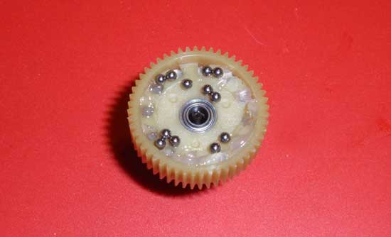
Drop the 2nd 5/32 bearing into place and drop the diff gear over it. The bearing should sit flush with the gear as shown. Now fill each diff ball hole with a dab of clear diff fluid. I usually drop the balls into the gear (as shown) and roll them into the holes. The diff grease helps keep them from falling out of the assembly and onto the floor. Make sure each hole gets a diff ball.
Step 5
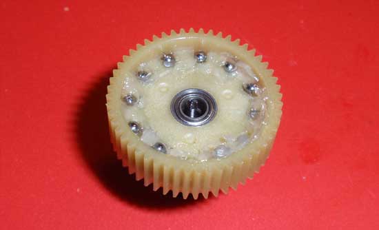
Your assembly should look like this so far.
Step 6
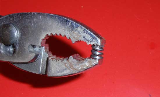
Pre-compress the diff spring with a pair of pliers. One or two full compressions should be good.
Step 7
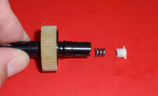
Slide the opposite diff out drive into place, making sure the diff thrust assembly does not get pushes out of the ‘female’ diff side. Now drop the diff spring and locking t-nut into place. Note the orientation of the t-nut. Tighten the diff thrust assembly into the t-nut. Every 2-3 turns, ‘work’ the diff but rotating the outdrives in opposite directions. This should help seat all the internal parts. Tighten until the t-nut bottoms out, but DO NOT overtighten. For starters, loosen the diff thrust bolt approximately 1/8 of a turn. ‘Working’ the diff again, it should feel extremely smooth.
Step 8
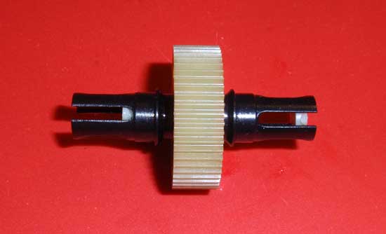
If all goes well with step 36, slide the diff cover into the diff thrust side as shown.
Step 9
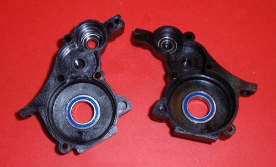
Now we’re moving on to the transmission case. Start but pressing a 10x66mm and 3/16 bearing into both sides of the case as shown. They should be somewhat snug. If they are not going in easily, do not force them. They need to go in perfectly straight for a nice, smooth transmission.
Step 10
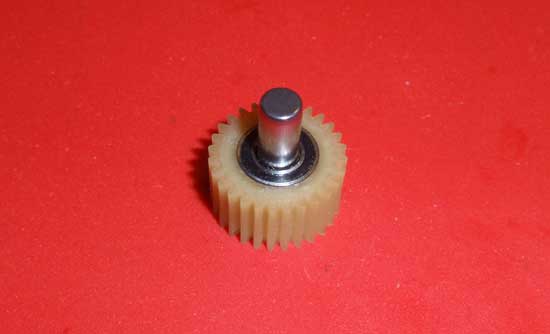
Press 2 more 3/16 bearings into the idler gear. Insert the idler gear shaft into the assembly.
Step 11
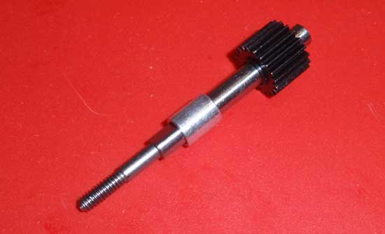
Slide the top shaft spacer onto the top shaft as shown.
Step 12
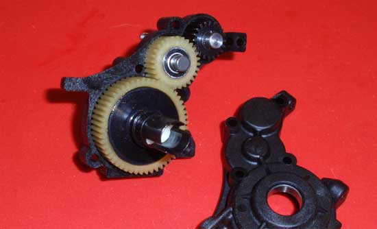
Slide the top shaft into the case, followed by the idler gear assembly and finally the differential. Make sure you insert the diff with the diff thrust screw facing out of the case. This will keep the diff from loosening up while driving.
Step 13
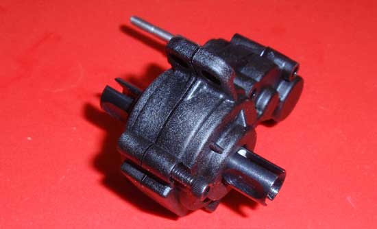
Slide the opposite transmission case half into place and secure with the single 4/40×1/2 screw (for now). Do not insert the other screws yet; they’ll be a pain to deal with while we finish up this part of the assembly.
Step 14
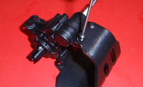
Attach the motor guard to the top of the transmission case with the 2 4-40 screws.
Step 15
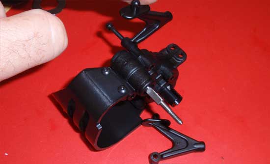
Attach the wing mounts/body mounts to the transmission with the 4-40×1 1/4 screw. Note that there is a left/right wing mounts/body mount; they are keyed to the transmission. Be sure you have them on correctly.
Step 16
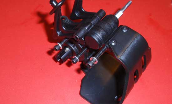
Now you can insert the 3 4-40×1 screws into the transmission. Be sure to slide the washers on first.
Step 17
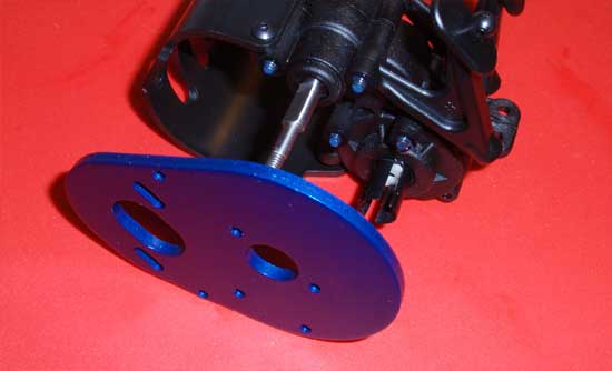
Place a small drop of blue thread locker onto the 4 screws that are sticking out (the 3 1″ and the wing mount/body mount screw). Line up the FT motor plate and secure with the 4 screws. Tighten down until the screws are snug; do not overtighten.
Step 18
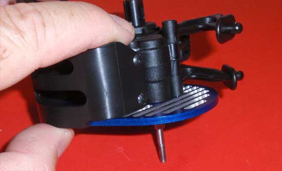
Finished assembly. Make sure the wing mounts/body mounts can move slightly. We’ll need to re-position them in a later step.
Step 19
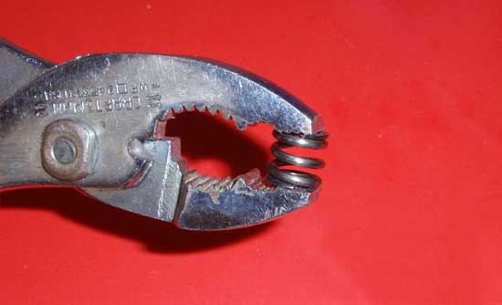
Pre-compress the slipper spring like we did to the diff spring in step 35.
Step 20
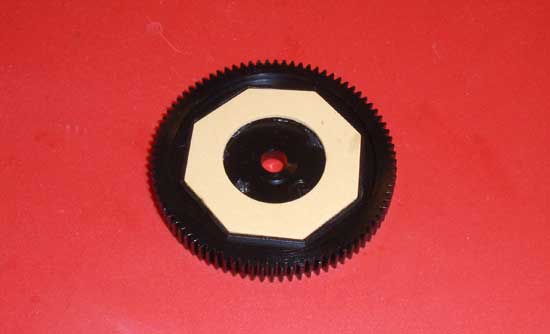
Press the octagonal pad into one side of the gear as shown. It might stay or it might not. If it doesn’t, further assembly could be a little trickier.
Step 21
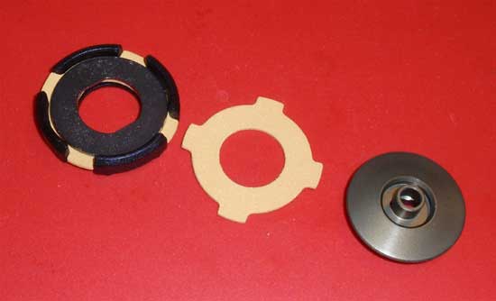
Press one of the VTS slipper pads into the VTS slipper housing followed by the VTS slipper plate, the 2nd VTS slipper pad and then the VTS outer hub.
Step 22
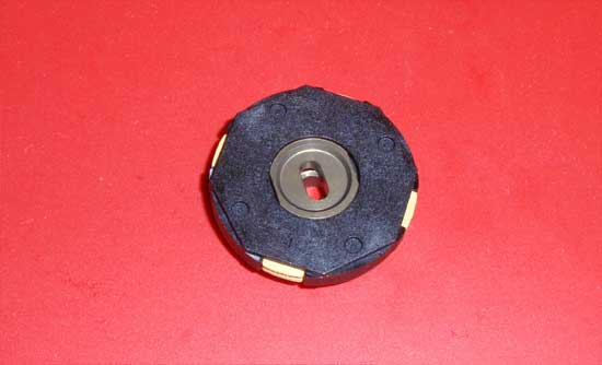
Your assembly should look like this. Make sure the parts are all keyed together (the VTS outer hub and VTS slipper plate).
Step 23
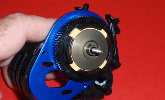
Slide the FT V2 slipper hub onto the top shaft followed by the 84T spur gear (note the orientation of the gear with the slipper pad from step 50). It is extremely important that the slipper pad stays seated in the grooves of the gear during this step. Finally, slide the VTS slipper assembly onto the top shaft.
Step 24
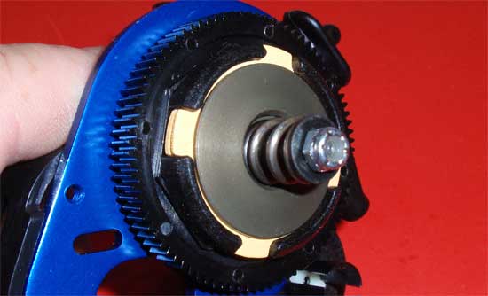
Slide the slipper spring into place followed by the V2 slipper washer and 5-40 locknut. Tighten the locknut down until it holds the assembly in place, then check to make sure the rear slipper pad is still seated in the grooves of the spur gear. If everything looks good, continue tightening the 5-40 locknut down until the end is flush with the top shaft. That’s it…transmission done!
Team Associated Factory Team T4.2 Online Build – Part 4
The rear suspension of the Factory Team T4.2 is extremely adjustable, allowing changes from camber, anti-squat, toe and roll centers. I will be building the kit with the stock setup, however some of the steps will be different for ease of the build.
Build Notes:
• You will be using black grease to build the CVA’s so it is suggested that you have some paper towels handy for clean up.
• Pay attention to the rear hub build. While not easy to easy to build backwards, you’ll want to make sure you do assemble them on the right side of the car.
Step 1
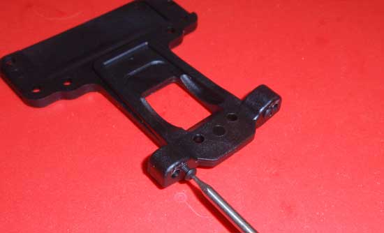
To begin the rear suspension, start by screwing in the 2-56 screws into the rear chassis plate as shown.
Step 2
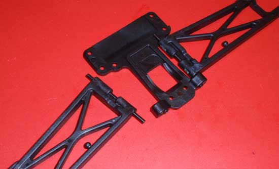
Next, slide the long hinge pins through the arms and then into the rear mounts in the chassis plate. The screws you attached in step 54 will help keep the hinge pins from sliding through the chassis plate.
Step 3
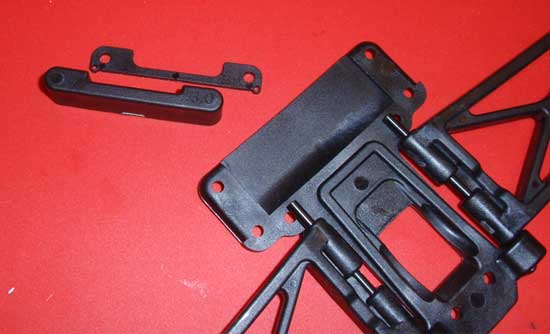
Install the rear arm mount onto the hinge pins. Have the anti-squat shim ready for the next step.
Step 4
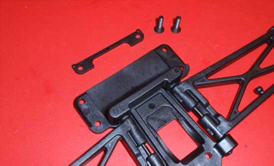
The arm/arm mount assembly should stay together pretty well, so slide the anti-squat plate into position and attach with the 5-40×1/2 screws. A Team trick is to cut a notch in the anti-squat shim where the holes are so that, after you insert the screws into the rear arm mount, you can slide the anti-squat shim into position (and remove it). This makes it easy to change anti-squat plates without having to remove the screws.
Step 5
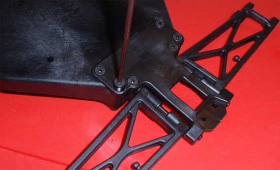
Attach the rear chassis plate assembly to the chassis.
Step 6
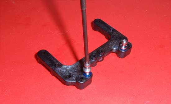
Slide a blue FT washer on and carefully install the silver ballstuds into the rear chassis brace. These hole locations have a tendency to strip under heavy use so do not overtighten…just snug down.
Step 7
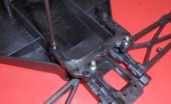
Attach your rear chassis brace assembly to the chassis. The instructions show to install the rear ballast weight but don’t do that yet. You’ll just piss yourself off since there is nothing there (yet) to keep it in place.
Step 8
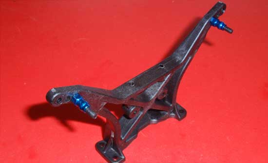
Assemble the rear shock tower as shown. Pay attention to the orientation of the tower to the shock screws.
Step 9
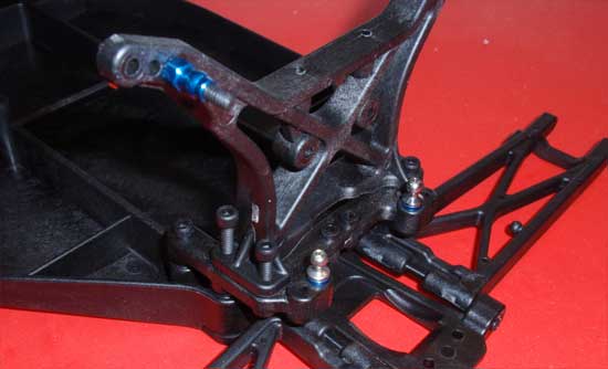
Attach the rear tower assembly to the rear chassis plate. Note there are 2 different lengths of screws uses here; 5-40×9/16 and 5-40×7/16. Use the longer, 9/16 screws in the front-most holes.
Step 10
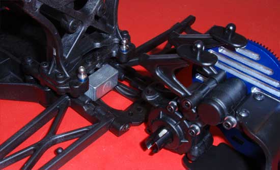
NOW you can set the ballast weight in place and slide the transmission into position.
Step 11/h3>
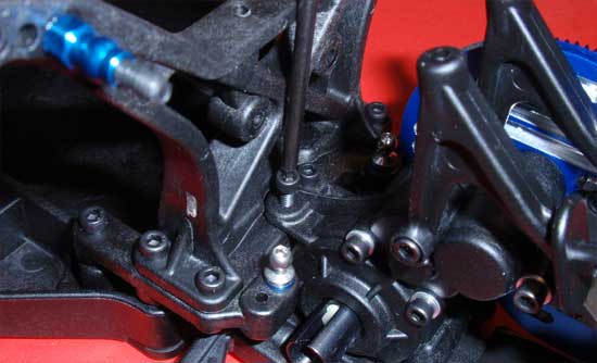
Rotate the wing mounts/body mounts up and out of the way and attach the transmission screws first. Having the wing mounts/body mounts out of the way gives us better access to these screws.
Step 12
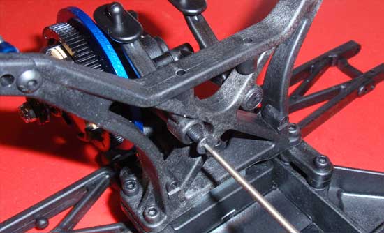
Rotate the wing mounts/body mounts into position and attach to the shock tower.
Step 13
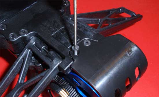
Flex the lower part of the rear bumper/motor guard to slide UNDER the chassis (as shown) and attach. Do not overtighten these screws.
Step 14
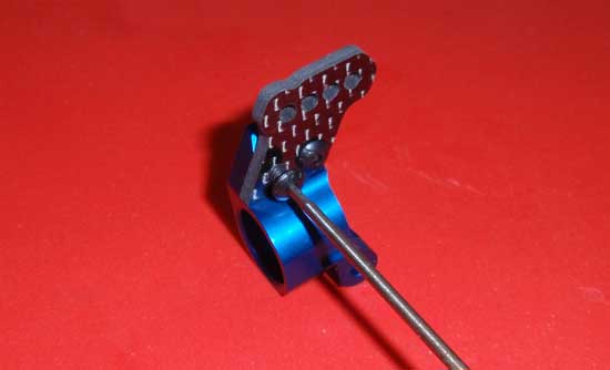
Build a left and right rear hub. The right rear is shown here. A dab of thread locking material would be a good idea as well.
Step 15
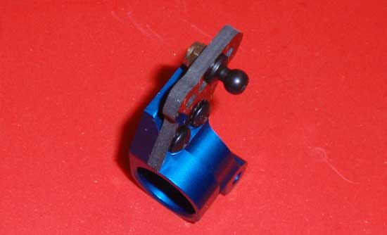
Attach the upper ball link to both hubs. Note the orientation of the ballstud to the hub.
Step 16
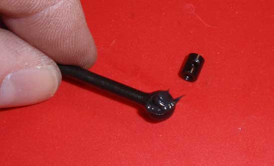
Moving on to the CVAs. Goop a good bit of black grease onto the CVA and insert the CVA barrel.
Step 17
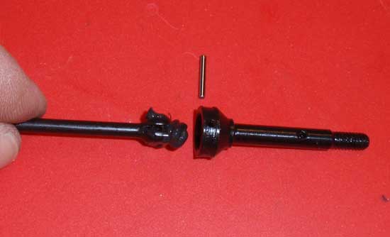
Goop some more black grease and slide the CVA into the axle as shown. Align the pin holes and slide the cross pin into place.
Step 18
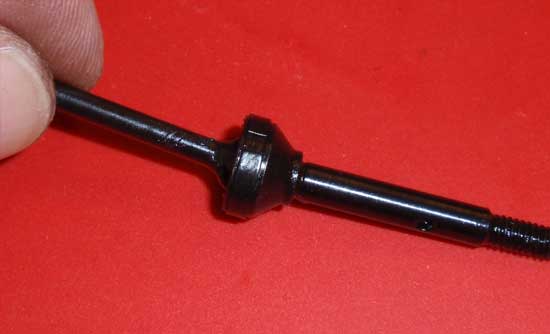
Snap the CVA pin retainer into place. The instructions state to put a drop of CA on the pin retainer’s ‘opening’, but I’m not sure that necessary. I’ll leave that step up to you. All I can say is that it obviously can’t hurt.
Step 19
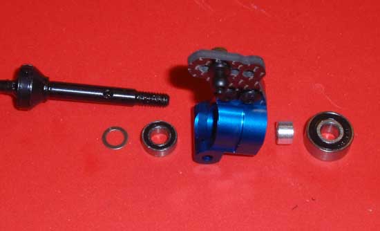
Take both CVA assemblies and install them into both rear hubs. Start by placing the 3/16 axle shim onto the CVA axle followed by the 3/16×3/8 bearing. Slide that into the rear hub, making sure to seat the bearing ‘square’ with the hub. Slide the crush tube onto the axle followed by the larger .187x.196 bearing, pressing the bearing all the way into place.
Step 20
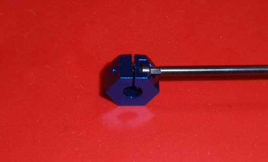
Insert the 2-56 screw into the 12mm clamping wheel hex.
Step 21
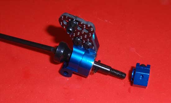
Press the 1/16 roll pin into the axle. Slide the wheel hex assembly onto the axle, aligning the roll pin and the groove in the hex. Once pressed into place, tighten the 2-56 screw in the hex to keep it in place.
Step 22
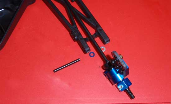
Take your assembled hubs and attach them to the rear suspension arms. Insert the hinge pin into the arm, through the blue washer, the hub and then the silver washer. Make sure the hinge pin fits flush with the outside of the arm. Also note the orientation of the rear hub.
Step 23
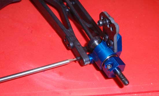
Insert the 2-56 screw in place to secure the hinge pin.
Step 24
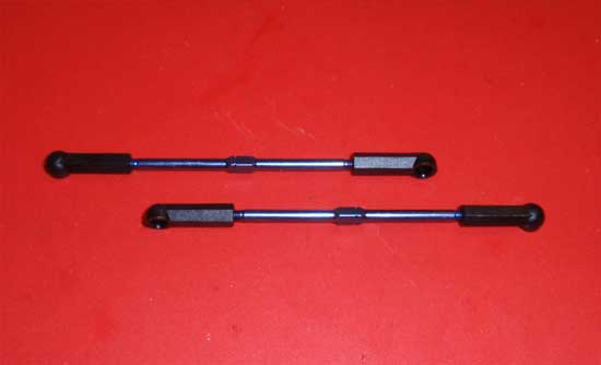
Build a pair of rear turnbuckles. The lengths are good per the instructions.
Step 25
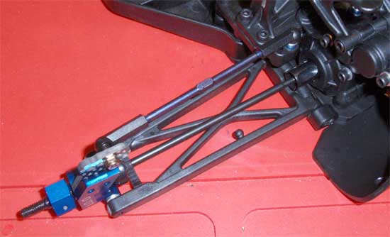
Slide the CVA into the rear diff outdrive and pop the ballcups onto into place. Be sure to ‘align’ the notches on the turnbuckles so that they coincide with the front turnbuckles.
Team Associated Factory Team T4.2 Online Build – Part 5
The shocks are up next, and Team Associated is well known for having some of the best shocks in the industry. The Factory Team T4.2 comes with the A-Team’s 12mm Big Bore shocks complete with bottom load seals and bleeder caps. You can’t get much better than this in 1/10th scale!
Build Notes:
• You will be filling the shocks with shock fluid and, of course, bleeding them so it is suggested that you have some paper towels handy for clean up.
Step 1
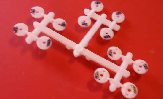
The shock pistons have a small number molded into them (1.6, 1.7 etc), but they are extremely hard to see. To make them a little easier, I used a Sharpie to color the area over the number. For this build, I’ll be using the stock shock pistons per the manual (1.6 front, 1.7 rear). Sorry for the blurry pic.
Step 2
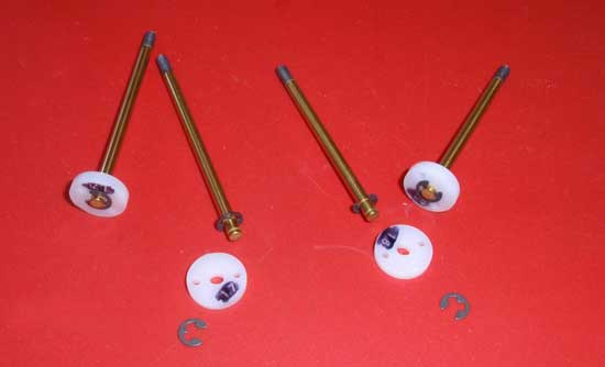
Snap an e-clip into the lower groove on the shock shaft followed by the shock piston. Secure with the 2nd e-clip. Make sure you put the 1.6 pistons on the shorter shafts and the 1.7 pistons on the longer shafts.
Step 3
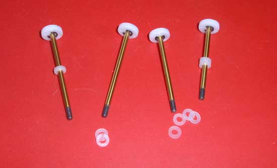
We will be putting down-travel limiters on the shafts, 4 on each front shaft and 2 on each rear shaft.
Step 4
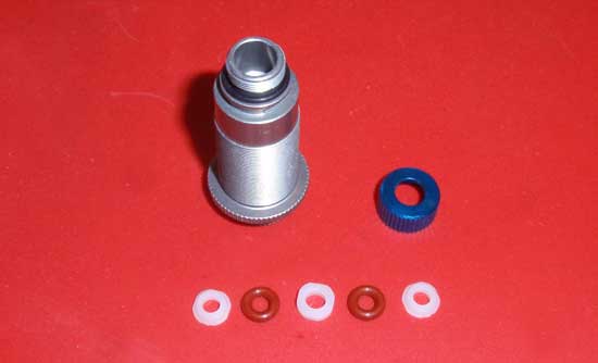
Grab your shock bodies and slide one of the small, black o-rings over the shock seal opening as shown. As you can see, we’ve prepped the pieces to install in the shock seal area.
Step 5
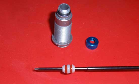
Time to build the lower seals. I like to put them on a tool so that I can lube up the parts without making too much of a mess. Take any driver (preferably one that is smaller than the holes in the parts) and start by installing a shock hat bushing (make sure the lip is facing INTO the shock body) followed by ared o-ring, shock spacer, red o-ring and then another shock hat bushing (make sure, with this one, the lip is facing AWAY from the shock body). Apply a drop of two of shock oil and make sure all the parts are well lubricated.
Step 6
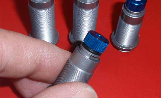
Insert the parts into the lower area of the shock and make sure they all seat properly. Attach the lower shock cap, making sure to align the hole in the cap with the lip on the shock hat bushing. Tighten all the way down.
Step 7
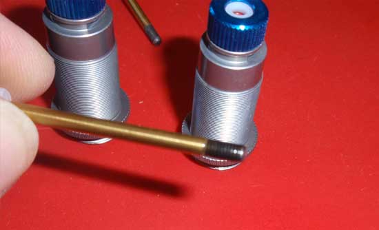
Put an additional drop of shock oil on the threads of the shaft. Yes, another blurry pic…but at least the shock body is in focus.
Step 8
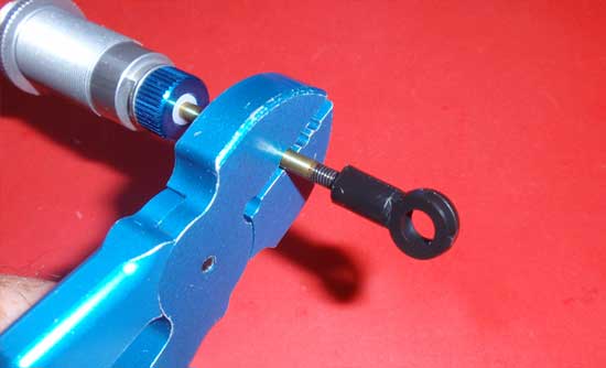
Slide the shock shaft assembly into the body (make sure you put the shorter, front shafts into the shorter, front shock bodies) and slide it down through the seal assembly. The shock oil allows the shaft’s threads to pass through the seals without tearing them. Now install a shock eyelet on each of the 4 shocks, screwing them on to the top of the threads. Be careful when holding the shock shaft that you don’t scratch it when installing the eyelet. I use a pair of STRC’s shock holding pliers. Great tool; holds tight, doesn’t scratch the shock shaft.
Step 9
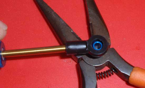
Pop one of the Factory Team pivot balls into each of the eyelets. I suggest doing this on a solid surface…it just makes it easier. I used the side of my needlenose pliers.
Step 10
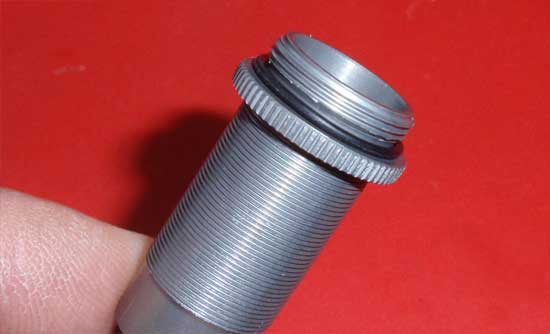
Wrap one of the larger o-rings onto the top of each shock as shown.
Step 11
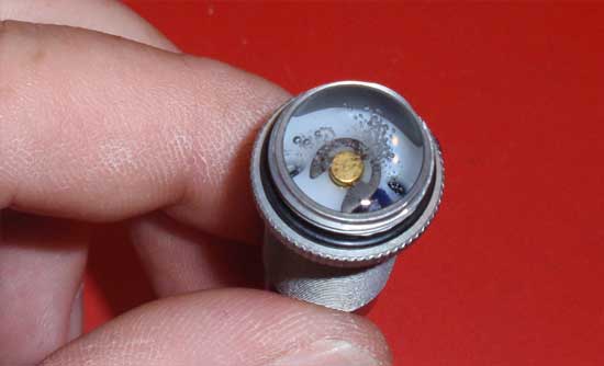
Pull the shaft down (so the piston sits at the bottom of the shock) and fill it with oil to ALMOST the top. Slide the shock shaft up and down so the oil can filter through the piston and fill up the bottom of the shock (under the piston). Doing this, you will see the air bubbles rise to the top. You want to get rid of all of these bubbles.
Step 12
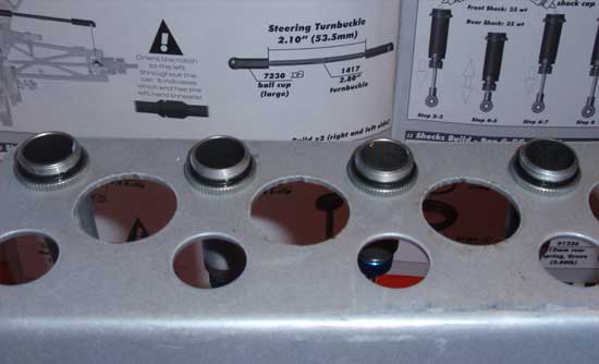
Place your shocks in a shock stand for about 5 minutes. This will allow all the air bubbles to rise to the top. I use on of Team Fast Eddy’s shock stands to hold mine. This shock stand has holes to fit 1/10th, 1/8th and 1/5th scale shocks. Once the bubbles are gone, refill the shocks to the top.
Step 13

GO WASH YOUR HANDS WITH SOAP! I can’t emphasize this enough. You will be inserting the other larger o-rings into the grooves of the shock collars and if your hands have oil on them, it can make this a very frustrating task. It takes 20 seconds…go do it. I’ll wait.
Step 14
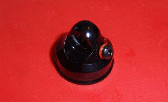
Now that you have clean hands (and your shock collars are built), we’ll move on. Take one of the 2x4mm screws, slide a shock cap o-ring onto it and feed it into the shock cap hole. Tighten down a bit, but not all the way. Build 4 caps.
Step 15
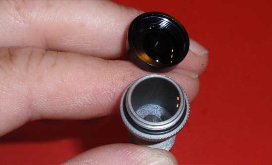
Take your shock cap and put a drop or two of shock oil into it. Now, flip it over and screw it down onto the shock. Be extremely careful that the black o-ring (on the top part of the shock body) fits UNDER the shock cap when you tighten it down. If it ‘squeezes’ out the side of the cap, the assembly won’t seal and you’ll have a leaky shock. Build 4 shocks.
Step 16
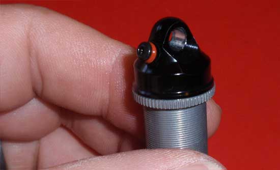
Now loosen up the shock cap screw and slowly push the shock shaft up. You’ll see some oil come out of the shock cap hole. When the shaft is to the top, tighten the shock cap screw. Do not overtighten as you need the red o-ring to seal the hole. Do this to all 4 shocks.
Step 17
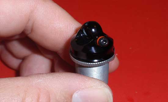
Another view of your sealed shock cap.
Step 18
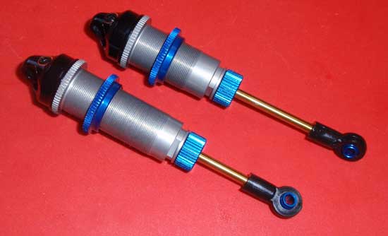
Once the caps are on and secure, thread the shock collars onto all 4 shocks…
Step 19
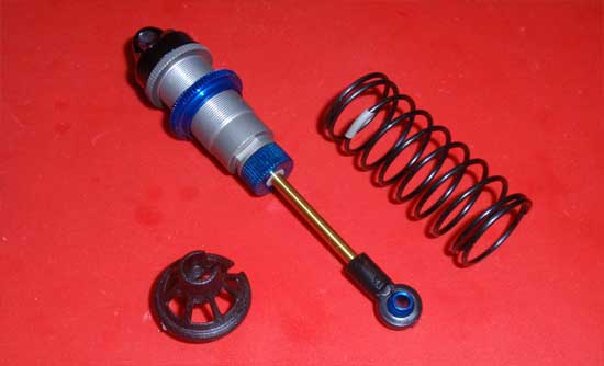
…followed by a spring and the lower spring retainer cup. Make sure you put the shorter springs on the front shocks and the longer springs on the rear shocks.
Step 20
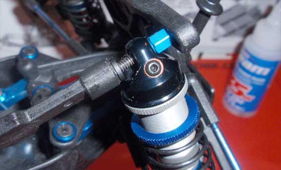
Attach the top of the front shocks to the tower and secure with the shock mount nut. Do not overtighen; you want the shock to have a little bit of wiggle.
Step 21
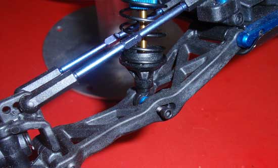
Slide the lower part of the front shock into the gap in the front suspension arm. Attach (in the outside hole) with the 4-40 screws. Do this on both sides (and make sure both lower mounting positions are in the same hole).
Step 22
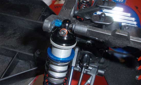
Attach the top of the rear shocks to the tower like you did with the fronts.
Step 23
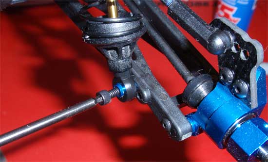
Using the 4-40 screw, attach the bottom of the shocks to the rear suspension arms. Make sure both sides use the inside mounting hole.
Team Associated Factory Team T4.2 Online Build – Part 6
The next step involves installing the electronic gear. As mentioned before in the build Table of Contents, we’ll be using a Team Associated XP DS131 steering servo, LRP Flow brushless ESC, Reedy Sonic 17.5 brushless motor and a Reedy WolfPack LiPo battery. Vintage car with current technology…a winning combo!
Build Notes:
• No real tricks involved with this step other than making sure you solder the wires onto the motor in the correct sequence; A wire to A tab on the motor, B wire to B tab, etc.
Step 1
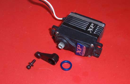
First we’ll install the XP DS1313 servo. AE has included different servo horns for a variety of servos, so make sure you choose the one that is designed for your servo. Fit the ballend to the servo horn as shown, then install the blue expansion ring. Finally, attach the servo horn assembly to your servo, making sure the servo horn is just slightly off 90 degrees (see manual). You’ll be using the screw that came with your servo to secure the horn.
Step 2
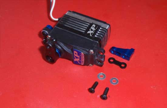
Attach the servo mounts to the servo as shown, but do not tighten the screws yet. You can use the Servo Chart on page 17 of the manual to figure out which spacers to use.
Step 3
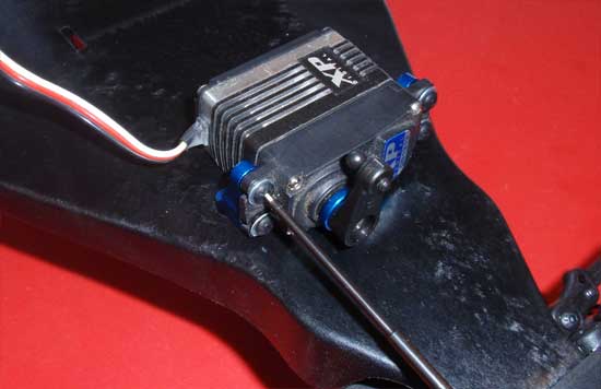
If you tightened down the servo mounts in step 103, the holes for mounting to the chassis may not line up when you install the servo assembly into the chassis. If you loosen them up and re-install, you’ll see that you won’t be able to tighten them once it’s in the chassis. The fix? Simply mount the servo to the BOTTOM of the chassis first! Line up the holes in the chassis, insert the 4-40×3/8 screws from the other side and snug down. Now tighten the servo mount screws. Remove the 2 screws attaching the assembly to the chassis, flip the servo to the inside of the chassis and secure with the 2 4-40 screws again. The holes will line up perfectly!
Step 4
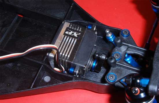
See, a perfect fit without driving you crazy trying to tighten up the servo mount screws.
Step 5
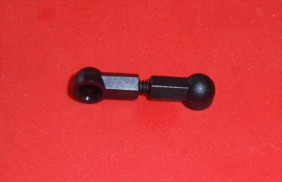
Build the servo link assembly per the instructions…
Step 6
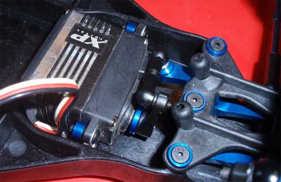
…and pop into place between the servo horn and the steering system.
Step 7
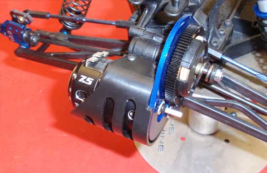
Slide your motor into place at attach to the motor mount using the M3 screws. Don’t forget the washers. Do not tighten all the way down yet.
Step 8
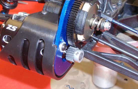
Slide your pinion on the motor shaft and align it with the spur gear. Make sure there is complete tooth contact, then tighten down the pinion’s setscrew to secure. You’ll also want to set the gear mesh at this point. Page 18 in the manual has good instructions on how to do this.
Step 9
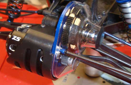
Attach the gear cover to the motor mount as shown and pop the dust cover button into place. I lost the 2 4-40 screws used in this step but thankfully have some blue, Factory Team ones to replace them.
Step 10
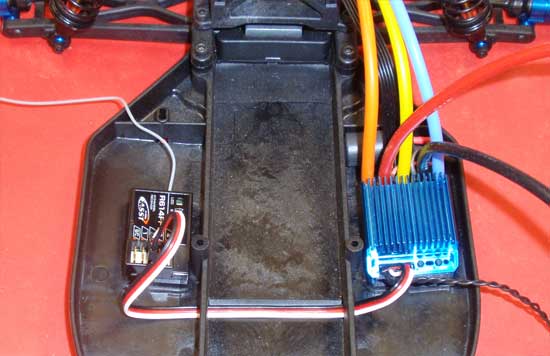
Tape your receiver and ESC into place as shown, slightly behind the channel running across the middle of the chassis. Try and get them as close to the center as possible for better weight distribution. Feed the ESC power lead through the slits in the chassis, resting it in the channel. Plug it in to the receiver.
Step 11
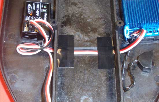
This ESC power lead will move around a bit, so I usually tape it into place to secure it. This is also a good time to plug the servo lead into the receiver and mount the ESC switch.
Step 12
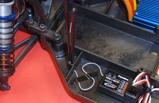
Run the receiver antenna down through the chassis and back up through the hole. Feed it into the antenna tube and press the antenna tube into the chassis. Secure with the 5-40 setscrew. I use a little tape to keep the receiver wire from flopping around as well. Just be sure not to crimp the wire.
Step 13
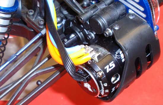
Feed the motor wires to the motor (through the shock tower) and solder into place. Remember, A wire to the A tab, B wire to the B tab and C wire to the C tab. Feed the sensor wire through as well and press into the motor.
Step 14
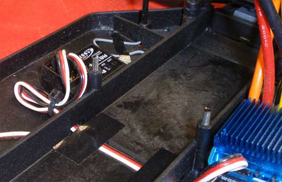
Screw the 4-40 setscrews into the battery mount holes as shown.
Step 15
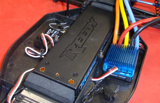
Place the battery into the truck. Team Associated has supplied 4 foam pads (2 thick, 2 thin) so you can space the battery forward or back for better weight distribution. Since I’m not 100% sure how I want them to be yet, I placed them per the manual; 1 thick/1 thin up front, 1 thick/1 thin in the rear.
Step 16
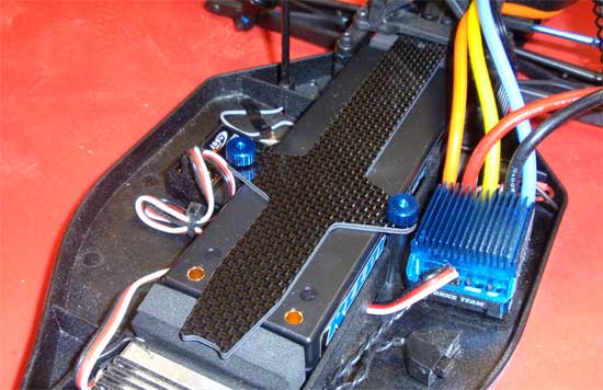
Slide the rear of the carbon fiber battery strap underneath the rear tower and drop into place (the holes in the strap should fit over the 4-40 setscrews). Secure the strap with the 2 Factory Team blue thumbscrews.
Team Associated Factory Team T4.2 Online Build – Part 7
The final step in the Factory Team T4.2 build is the wheels, tires and body. For this step we’ll be using a full set of Proline’s Hole Shot T’s in their soft M3 compound. We will also be mounting the Proline’s Bulldog body painted up by none other than Larry over at Kustom RC Graphics.
Build Notes:
• We’ll be gluing up some tires, so I would suggest getting some tire-gluing bands and a good CA glue. I’ll be using Proline’s glue and LeadFinger Racing tire bands.
Step 1
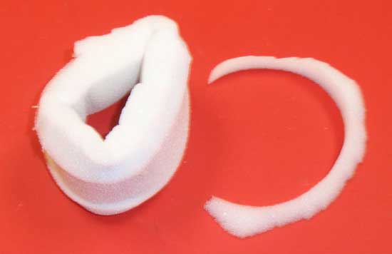
We start this tire-mounting process by first cleaning the tires to remove any oils or releasing agent left on the tires. We also cut a thin strip of the insert off to allow the tires to mesh better on the wheels. Turn the insert inside-out and cut a strip as shown. Not everyone does this, but I like to just because it makes mounting easier.
Step 2
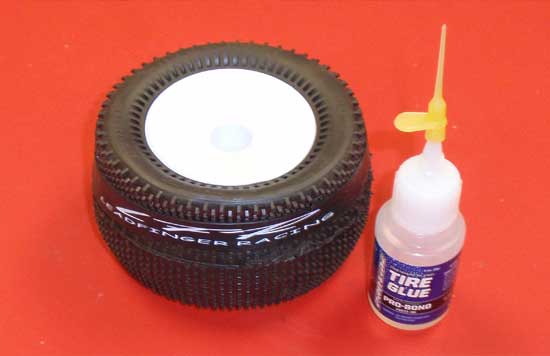
Fit the insert into the tire and wrap the tire around the wheels. Wrap your tire-gluing band around the tire and make sure the tire bead is pressed into the wheel channel. Using your glue (and a glue tip similar to CompetitionX’s Gloo Toobs), pull the tire back slighly and apply the glue. You’ll want to do all the tires on one side, then set them aside to dry (approximately 30 minutes for a good set). Flip the tires, move the tire-band to the other side of the tire and finish gluing the opposite side.
Step 3
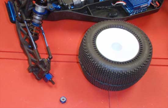
Once the glue has dried, you can mount the tires to the Factory Team T4.2 using the 8-32 wheel nut.
Step 4
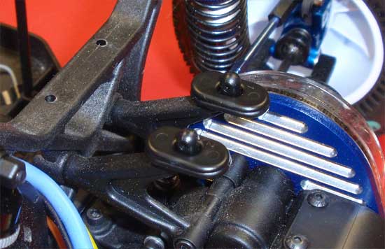
Don’t forget the wing shims…you’ll want to add these to help raise the rear of the body for a better fit. Note the orientation of the shims front-to-back.
Step 5
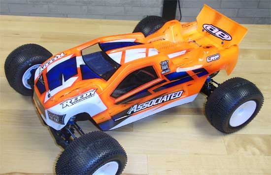
Finally, drop your freshly painted body onto the body mounts and secure with the body clips.
And there you have it, a complete build of the Factory Team T4.2! Thanks for following along and I hope you enjoyed the build!

