

Team Associated RC10 Classic Online Build
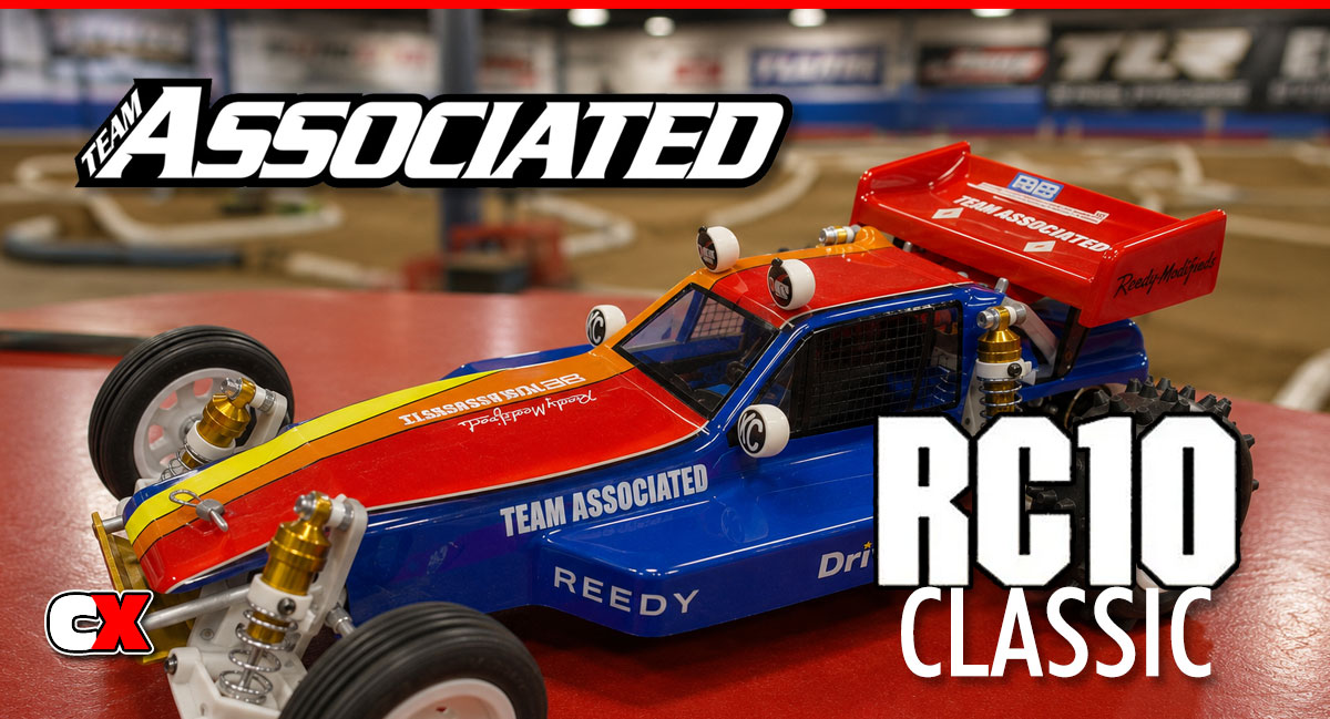
Team Associated has re-released the original RC10, now slated the RC10 Classic. This piece of history includes all the things that made this buggy an industry-changing car; white plastic parts, gold tub, big-spiked tires and three-piece wheels. It is a limited-release vehicle so if you’ve got one you’re one lucky fella (or gal!).
I was lucky enough to get one from the A-Team to do a full build and review on. As much as I hate to open the box, the plastic bags and paint the body, I’m taking one for the team to build this replica racer from 1984. Follow along as I assemble the RC10…maybe this might be enough that you won’t have to open your kit! Testing and my final thoughts will be posted in an upcoming review.
Team Associated RC10 Classic Online Build – Part 1
We start off the RC10 Classic build with the front suspension. If you’re a long time RC’er (or someone that just happened to have an original RC10 at one time), you’ll be happy to see all of the vintage-style parts in this kit. Let’s get started.
Build Notes:
• FIRST AND FOREMOST!!!! Do NOT throw away any of the tools AE has supplied. I’ll get to that more later, but if you decide not to use them, put them aside and, again, DO NOT THROW THEM AWAY!
• You’ll want to get your hands on a large-tip Phillips screwdriver for parts of this assembly. AE has included the old-skool aluminum Phillips screws and you don’t want to be stripping them out.
• Because this kit is from the way-back time-machine, the bags and their contents don’t coincide 100% with the manual. You may need to open bags further down the line to get the screws you need for an earlier step.
• Threadlock is also required during this assembly so have that ready as well.
Step 1
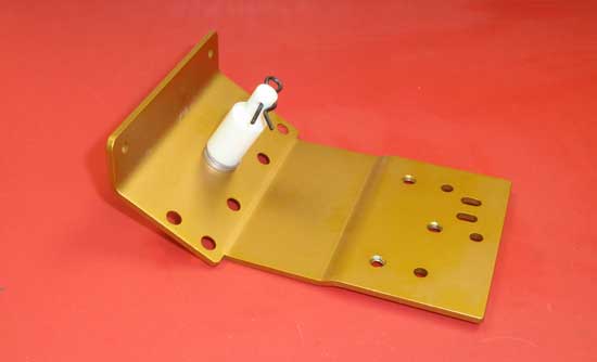
The first step is to attach the front body mount to the front nose plate. Using one of the 8-32 (yellow) aluminum screws, feed it through the front nose plate, through a pair of #8 washers and into the front body mount. To make tightening easier, I installed a body clip to give the body mount more meat to hold on to.
Step 2
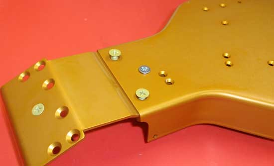
Attach the front nose plate to the chassis using two more 8-32 (yellow) aluminum screws and the short 8/32 screw (silver). Feed the yellow screws in first (but do not tighten) followed by the silver one. A drop of threadlock on the silver screw will keep it in place. After you’ve snugged the silver screw down, snug the yellow ones down.
Step 3
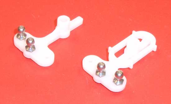
Assemble the steering rack arms as shown. The plastic on these is very similar to the original plastic from years ago, so be careful when tightening down the ball ends. SNUG them down…do not overtighten.
Step 4
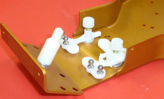
Slide a #8 washer over both yellow screws in the chassis followed by the assembled steering rack arms. Note which arm goes on which side. Slide the servo saver arm onto the LEFT side servo arm as shown and secure both steering rack arms with a 8-32 white nut. Tighten down until snug, then back off about 1/2 turn. You’ll want the steering rack arms to move freely but with as little slip as possible. Adjust the white nuts until you achieve this.
Step 5
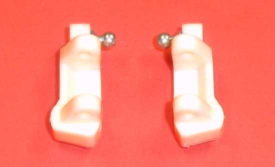
Install a ball end into both caster blocks. Note the orientation of the caster block.
Step 6
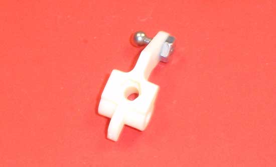
Assemble the steering blocks as shown. You’ll want to make a left and right side. A drop of threadlock will keep the nut attached to the ball end.
Step 7
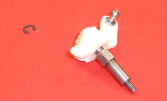
Align the hex on the axle with the hex on the steering block and slide it into place. It may take a little pressure to make it seat all the way into the steering block. Secure with an e-clip.
Step 8
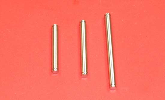
There are three different sizes of hinge pins included in this step. The one of the far left is the kingpin, the one in the middle is the outer hinge pin and the one on the right is the inner hingepin. Grab the one on the left…
Step 9
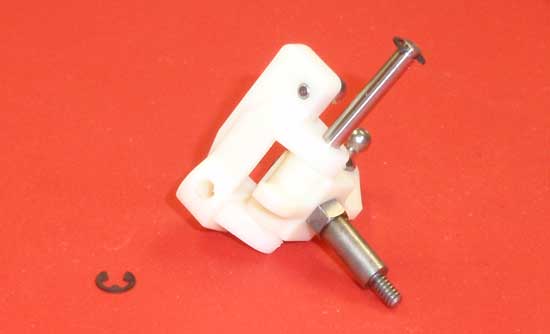
…attach an e-clip to one end and slide it through the caster block and steering block as shown. Note the orientation of the parts. Secure the kinpin on the bottom with another e-clip. Make both sides.
Step 10
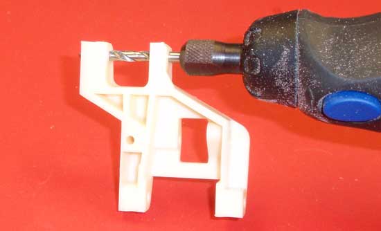
The suspension arms will require a bit of ‘massaging’ to make them move freely after assembled, so this is a good time to do it. Take your hinge pins and slide them through the arms…they should take quite a bit of pressure to push through and the arm will most likely not ‘swing’ on it. We’ll need to remedy that before we move on. Take a 1/8″ drill bit, attach it to your dremel or drill and, on a slow speed, ream out the inner and outer holes of your suspension arms. Test the hinge pin again. If the arms swings freely, you’re good to go. If not, repeat the reaming process until it does. Do this to both the inside and outside hinge pin holes on both arms.
Step 11
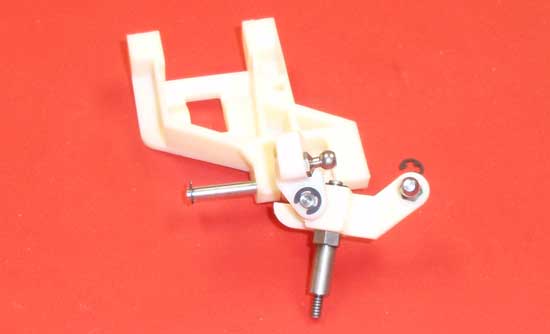
Using the ‘middle’ hinge pin (as described earlier), snap an e-clip to one end and attach the caster block/steering block assembly to the front suspension arm. Note the orientation. Secure with another e-clip on the other end of the hinge pin. Build both sides.
Step 12
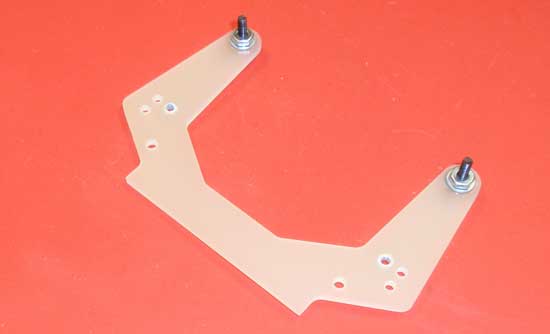
The next step is the shock tower. As you can see, old-skool shock towers were flat so there isn’t a front or back side…just a tower. Start by attaching the shock mount screws to the single hole in the top. The shock mount screws will be in a later bag so you’ll have to find them. Don’t forget the #4 washer and the drop of threadlock to keep the 4-40 nuts in place.
Step 13
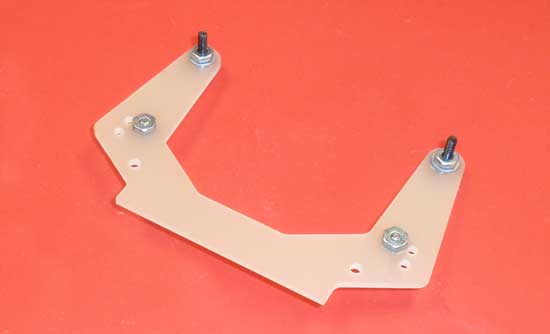
Slide the ballstuds into place and secure with a 4-40 nut. A drop of threadlock here is also required.
Step 14
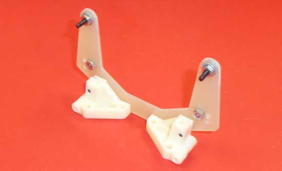
Attach the shock tower assembly to the left and right arm mounts as shown. Note the orientation of the arm mounts. When you’re done, press the assembly on a flat surface (as shown) and rotate the arm mounts until they are flat against the ground.
Step 15
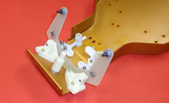
Now attach the shock tower/arm mount assembly to the chassis using 6 of the 8-32 (yellow) screws. Slowly tighten each one to make sure you don’t tweak the final setting point.
Step 16
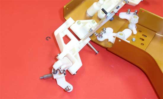
Snap an e-clip to one end of the longest e-clip and attach the left and right suspension arm assembly to the arm mounts. Secure with a final e-clip. I found that sliding the hinge pin up from the bottom (as shown) made snapping the 2nd e-clip on much easier.
Team Associated RC10 Classic Online Build – Part 2
In Part 2 of the RC10 Classic build, we jump into building an excellent rendition of the original 6-gear transmission. This transmission is simply over-complicated by todays standards and, because of this, the transmission build is a bit longer than most steps. It is a cool look at how things were done back then though!
Build Notes:
• In Step 1 I tried to make it extremely clear not to throw away any of the tools AE supplied with the RC10 Classic…and now you’ll find out why. In Step 7 you’ll need to screw in some itty, bitty 0-80 size screws into the RC10 idler gears. Ya, well, unless you’ve got an over-abundance of useless tools, you won’t have the L-wrench needed for this step. AE does supply it but, if you’re like me, I tossed out all those cheezy tools in favor of my awesome Hudy and MIP ones. Problem is, Hudy and MIP (or any other tool manufacturer in our industry) doesn’t make a 0-80 size wrench! So, yah, I had to order another 0-80 size wrench from AE. Moral of the story: don’t throw your RC10 Classic tools out. Ever.
• Have some threadlock ready as you’ll need it for this step.
• Because this kit is from the way-back time-machine, the bags and their contents don’t coincide 100% with the manual. You may need to open bags further down the line to get the screws you need for an earlier step.
• You’ll also be dealing with alot of grease, so a couple clean towels are recommended.
Step 1
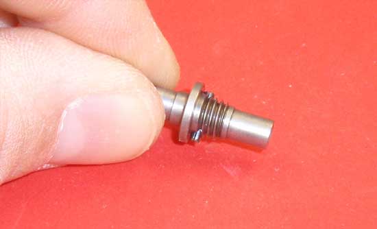
We start off the transmission build by pressing the drive pin through the drive gear pivot. This fit is a bit tight and might give you a bit of grief installing, but once you get it started just make sure it’s centered in the drive gear pivot.
Step 2
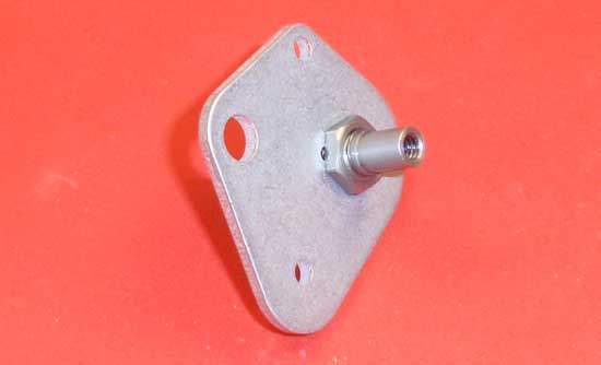
Slide the drive gear pivot assembly through the spine plate as shown and secure with the drive gear pivot nut. Note the orientation of the spine plate. Don’t forget to add a drop of threadlock to the drive gear pivot nut.
Step 3
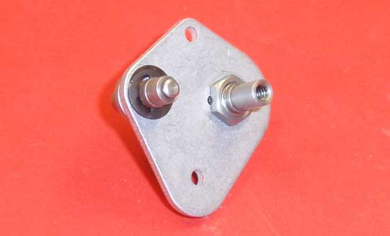
Slide the idler gear pivot through the spine plate, attach the 5mm washer and snap the larger e-clip into place as shown. Make sure you use the bowed e-clip and note the instructions on which side of the ‘bow’ faces out.
Step 4
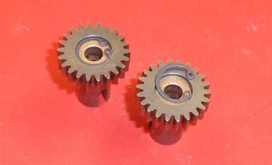
Press an oilite bushing into each of the axle drive gears. Make sure it seats all the way down into the gear and secure with an internal retaining clip (or snap ring). If you have a set of snap ring pliers, you can use those here to make things a bit easier. If you don’t, you can force one of the ‘open’ ends in and, carefully using your fingernail, rotate the snap ring into place.
Step 5
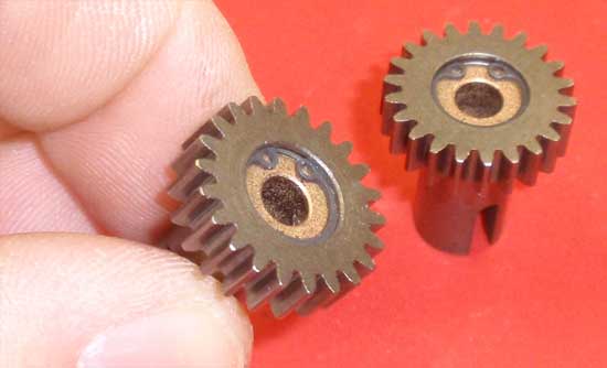
This photos shows the snap ring fully seated. Make sure both of your gears look like this.
Step 6
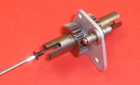
Slide the assembled axle drive gears onto the drive gear pivot as shown and secure with the 4-40 screw. A dab of threadlock will help keep the screws from loosening up.
Step 7
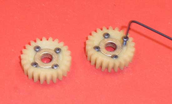
Press the oilite bushings into the idler gear and secure with 4 0-80 screws. You did save that itty, bitty 0-80 L-wrench, right? If you didn’t, you’re SOL until you fine another…don’t try and force the screws into place with a different wrench.
Step 8
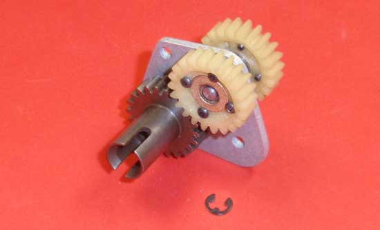
Slide the idler gears onto the idler gear pivot and secure with an e-clip. Note the orientation of the gear…you’ll want the screw heads facing out.
Step 9
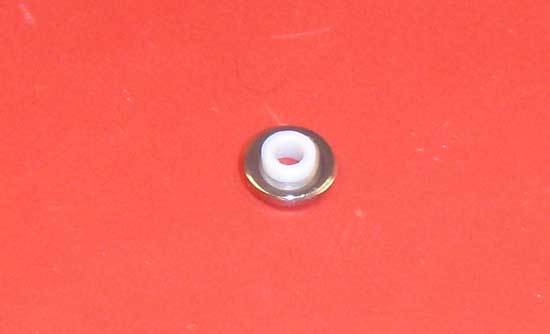
Before we assemble the top shaft, we need to do a little pre-prepping of parts. Trust me, it’s makes it alot easier! Start by pressing the white diff bushing into the thrust washer with the larger hole. Press in until one side is flush. You can use your table to achieve this (as shown in the photo).
Step 10
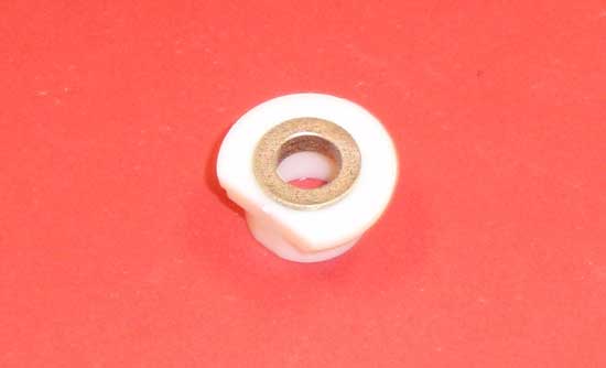
Press one of the larger oilite bushings into the bearing adapter. Make sure it is seated completely.
Step 11
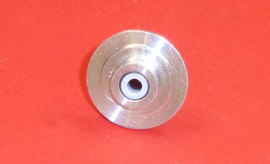
Finally, press the 2nd white diff bushing into the diff hub as shown. Make sure it is flush with the outside.
Step 12
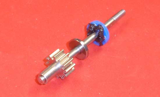
Now that the prepping is done, time to assemble. Slide the diff washer (with the smaller hole) onto the top shaft followed by the diff thrust bearing. Apply a small amount of black grease onto the ‘gear-side’ of the thrust bearing and slide down to the diff washer.
Step 13
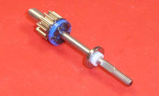
Apply a little more black grease onto the opposite side of the thrust bearing. Take your diff washer/diff bushing assembly and slide it onto the top shaft, the ‘flush’ side facing the thrust bearing. Slide it down and into place.
Step 14
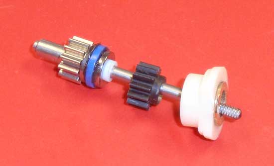
Slide the diff pinion onto the top shaft followed by your bearing adapter assembly. The diff pinion should slide over the white diff bushing and the bearing adapter should slide over the flange on the diff pinion.
Step 15
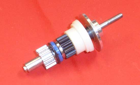
Take your diff tube assembly and slide it onto the top shaft (tube-side first) and press the entire assembly together.
Step 16
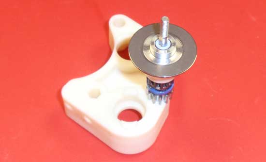
For the next couple of build steps, it’s easier if the top shaft is facing up. I used the transmission case half to hold the top shaft in place. Once you’re ready, slide a diff ring into place on the diff hub.
Step 17
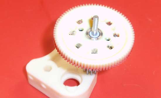
Slide the spur gear into place (over the diff hub) and squeeze a drop of white lube into all 8 holes as shown.
Step 18
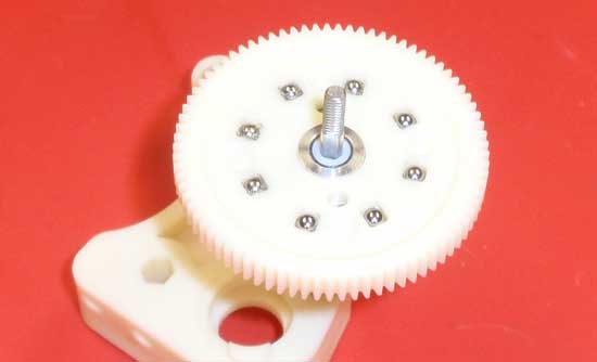
Drop one diff ball into each of the 8 holes. Be careful as these little suckers like to roll away and can easily be lost in the carpet.
Step 19
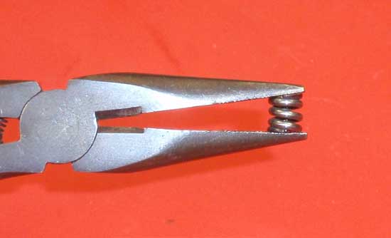
Prep the diff spring by compressing it 2-3 times with a pair of pliers.
Step 20
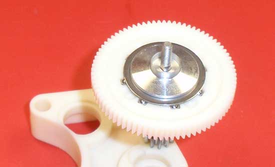
Drop the 2nd diff ring into place followed by the outer hub. Make sure the diff ring seats around the flange on the hub.
Step 21
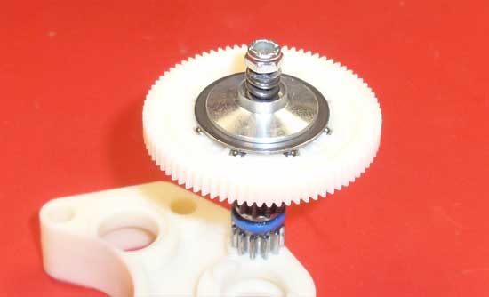
Drop the diff spring in place and attach the 5-40 locknut on the end. You can start with AE’s recommendation of tightening the locknut down until it is flush with the top shaft.
Step 22
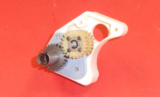
Ok, are you still with me? Well now we’re on to the fun part… Take your spine plate assembly and insert it into the right transmission case. Note the orientation of the spine plate in the picture.
Step 23

Slide the top shaft through the aluminum motor guard and through the upper hole in the right side transmission case. You’ll also want to make sure that the bearing adapter (on the top shaft) mates correctly on the outside of the transmission case.
Step 24
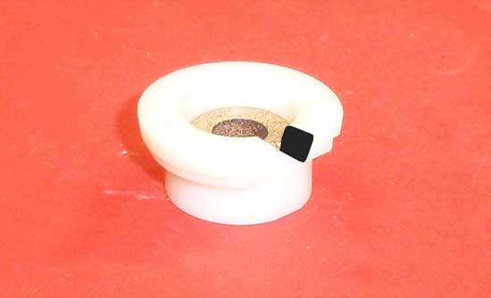
To help with the following step, cut a small notch in the final bearing adapter as shown. It doesn’t need to be a big notch, just something you can get a set of needlenose pliers into. Press the final oilite bushing into the bearing adapter.
Step 25
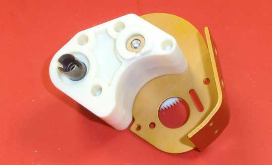
Press the bearing adapter into the left transmission case half. Using all three of your hands, align and press the two transmission cases halves together.
Step 26
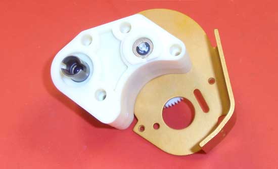
Drop the e-clip into the bearing area and, using the notch you cut earlier, snap it into place.
Step 27
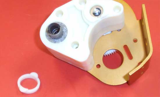
Press a felt ring over both of the diff outdrive gears followed by the felt seal. A drop of CA glue (on each ‘tab’) will help keep the felt seal in place. It should only take about 10 seconds to cure.
Step 28
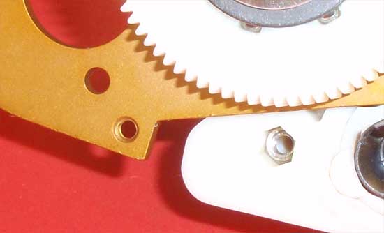
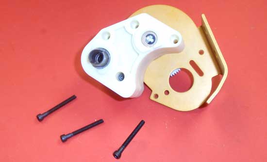
Insert the 4-40 plain nut down inside the hole as shown…
Step 29
…and secure the transmission together with the 4-40×5/8 screw. Do not over tighten, but do apply a small drop of threadlock. Now insert the 3 longer 4-40 screws and tighten them to the aluminum guard. A small dab of threadlock on these is also recommended.
Step 30
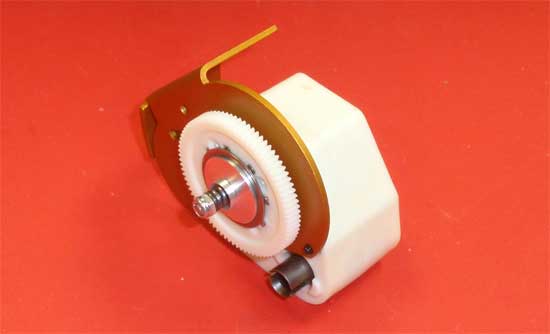
The final assembly should look like this and the gears should spin somewhat freely. Time to take a breather and get a beer. Good job.
Team Associated RC10 Classic Online Build – Part 3
The next assembly step involves attaching the rear bulkhead, shock tower and transmission to the chassis. Pretty straightforward with no surprises.
Build Notes:
• Have some threadlock ready as you’ll need it for this step.
Step 1
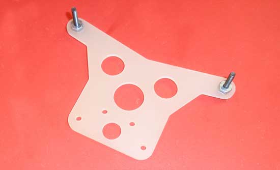
We start off by assembling the rear shock tower. Insert the two 4-40 screws through the tower and secure with the 4-40 nuts. The shock tower is not directional so it doesn’t matter which side you start with. Threadlock is recommended here to make sure the screws don’t loosen up.
Step 2
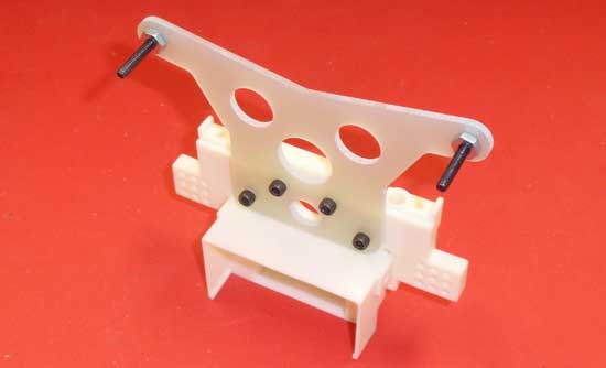
Attach the assembled shock tower to the rear bulkhead as shown. Note the orientation of the top screws.
Step 3
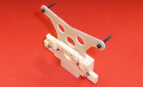
Flip the assembled rear bulkhead around and insert two of the silver ballends. I used the holes per the instructions, or the inner-upper holes. Do not overtighten these screws.
Step 4
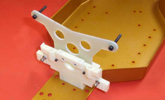
Wedge the bulkhead between the two tabs on the rear of the chassis and secure the bulkhead with two of the 8-32 yellow screws.
Step 5
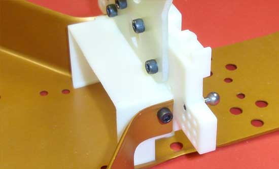
Insert and tighten two of the 4-40 screws into the side of the chassis tabs as shown.
Step 6
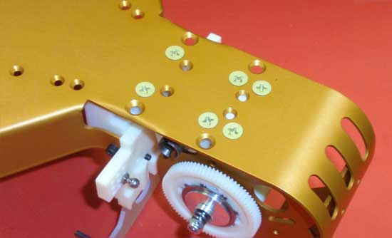
Place the transmission into place and secure it to the chassis with 4 of the 8-32 yellow screws.
Step 7
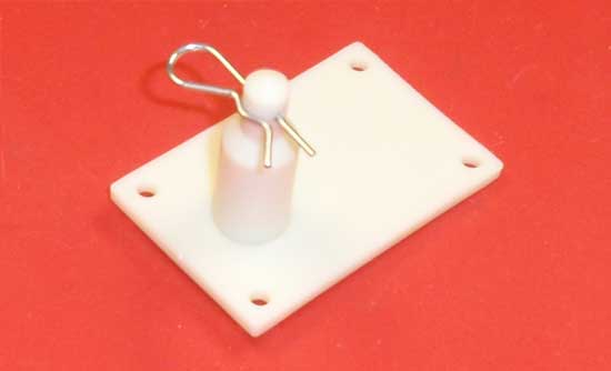
Attach the rear body mount to the transmission brace. As with the front body mount, I inserted a body clip to make holding onto the body mount much easier.
Step 8
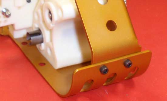
Thread the two 4-40 screws into the back of the motor guard and into the motor plate. Use threadlock to prevent them from backing out.
Step 9
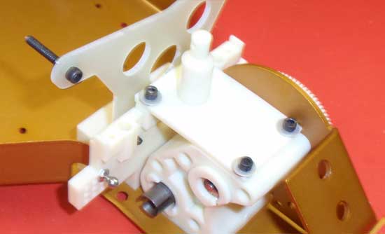
Attach the transmission brace as shown. Be sure the rear body mount is set to the front of the assembly. Do not overtighten these screws.
Step 10
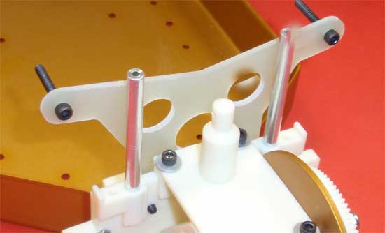
Insert the wing tubes into the holes as shown. This will take a little bit of pressure to do, so it is suggested that you place something soft over the top of the tubes and GENTLY tap into place with a hammer. The instructions say to use a dab of CA to keep them in place, but I would only suggest that if yours slide into the holes easily.
Team Associated RC10 Classic Online Build – Part 4
In Part 4 of the RC10 Classic build, we attach the rear suspension and assemble the turnbuckles.
Build Notes:
• Unlike current cars, the roll pins that feed through the rear axles are just that, rolled steel pins. They’re a pain in the butt to install and it is easy to pinch your fingers, so extreme care is suggested during this step.
• The turnbuckles are also old skool…threaded rod with ball cups on each end. Care must be taken here as well to not damage the threads during assembly.
Step 1
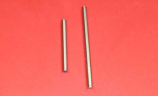
We’ll start off this step with getting our hinge pins in order. There are 2 sizes; a short and a long. The short is your outer hinge pin, used out on the hub carrier. The longer one is your inner hinge pin, used to connect the suspension arm to the arm mount. Let’s grab the two long ones and attach an e-clip to one side.
Step 2
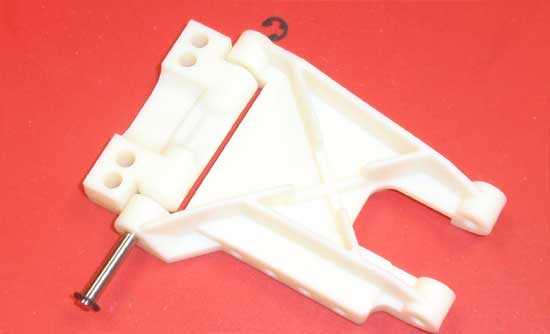
Slide the hinge pin through the arm/arm mount combo. The arms and mounts are directional so make sure you have the left arm mount with the left suspension arm and the right arm mount with the right suspension arm. Once assembled, secure the hinge pin with another e-clip.
Step 3
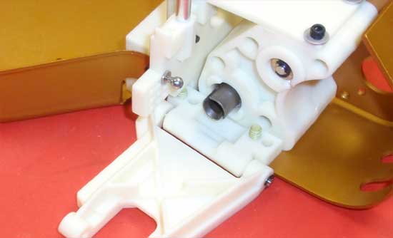
Attach both arm mount assemblies (right assembly to the right side, left assembly to the left side) to the chassis, as shown, using the forward set of holes.
Step 4
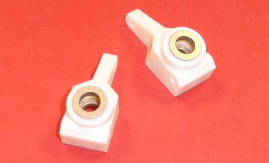
Press the four oilite bearings into the hub carriers as shown. Make sure they seat completely flat.
Step 5
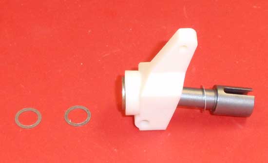
Slide one of the 1/4 axle shims onto the axle, then slide that assembly through the hub carrier. Finish that off with 2 more 1/4 axle shims.
Step 6
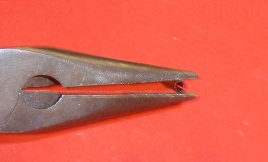
Here is the tricky part. The roll pin is going to be a slight bit bigger than the hole it needs to go into. To make installation easier, crimp one edge of the roll pin slightly, making this end slightly smaller in diameter than the rest of the pin.
Step 7
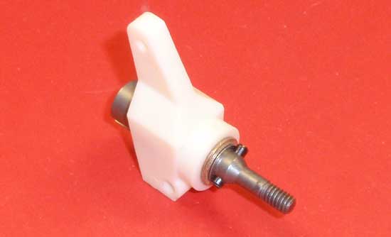
Press the roll pin into the hole in the axle with the smaller edge. Make sure you force the smaller edge you created in step 62 into the hole first. Center the pin in the axle as shown. This will require a little bit of patience.
Step 8
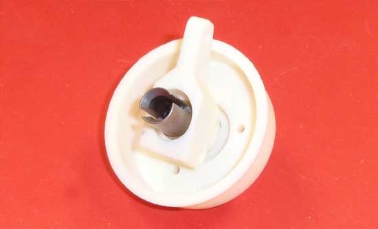
Test fit the hub assembly into the rear wheel, making sure the roll pin completely fits in the groove. If not, try centering the pin again.
Step 9
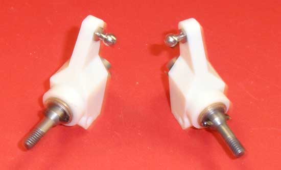
Here is a picture of both of the assembled hub carriers.
Step 10
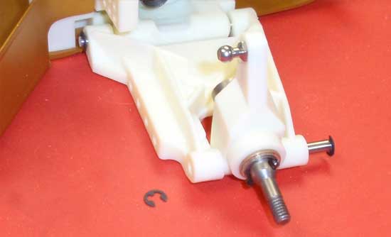
Grab the shorter hinge pin and attach an e-clip to one end. Now attach the hub carries to the rear suspension arms as shown and secure with another e-clip. Note the direction of the hub carrier, keeping the ball end facing towards the front of the car.
Step 11
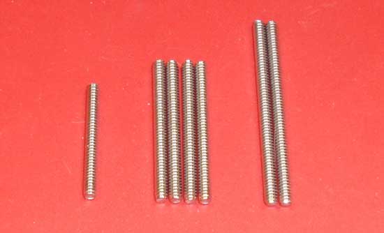
The turnbuckles on the RC10 Classic consiste of 3 lengths of threaded rod. The shortest one connects the steering bellcranks, the 4 mid-length ones are for the camber links and the 2 longest ones are for the steering.
Step 12
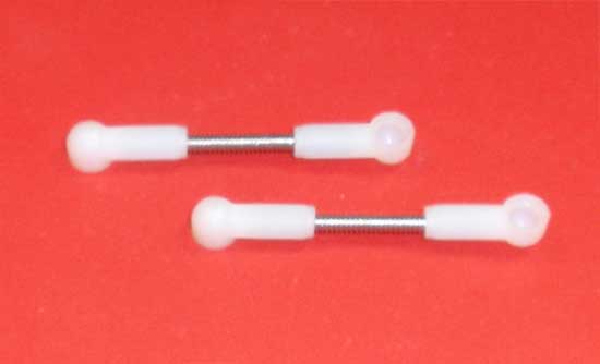
Grab a pair of the mid-length rods and build a pair of links as shown. Use the manual-supplied gap of 14.2mm. A pair of gloves or a spare rag will help keep the ballcups from cutting into your hands as you build.
Step 13
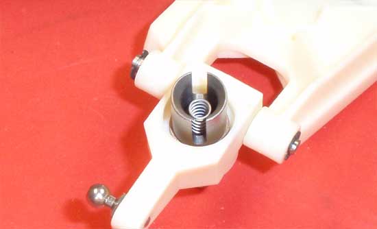
Insert the dogbone springs into the rear axles as shown.
Step 14
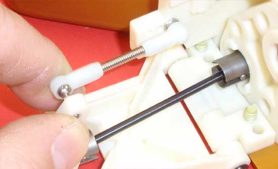
Pop one end of the turnbuckle onto the inner ball stud. Insert the dogbone into the transmission outdrive, swing up the rear outdrive and key the dogbone into the rear axle. Finish this assembly by popping the ballcup onto the ball stud on the rear hub. Do this with both sides of the car.
Step 15
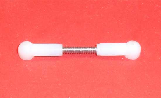
Grab the shortest-length threaded rod and build the drag link. The manual-supplied gap of 12.44mm is a good start.
Step 16
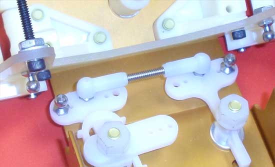
Pop the drag link onto the inner ball studs of the bellcrank as shown.
Step 17
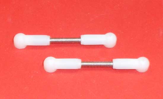
Grab the final pair of mid-length threaded rod and build a pair of front camber links. Use the manual-supplied gap of 13.5mm.
Step 18
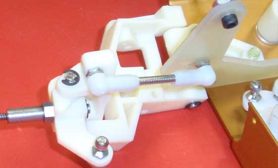
Pop the camber links onto the camber ball studs as shown.
Step 19
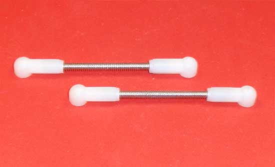
Grab the longest pair of threaded rod and build two steering links. The gap of 27.7mm is a good place to start.
Step 20
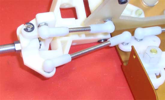
Pop the steering links into place as shown.
Team Associated RC10 Classic Online Build – Part 5
Part 5 of our build focuses on the shocks. Before you ask, yes, the shocks are ‘Classic’ as well, using the old-skool internal loading with the snap clips to keep the seals in place. While this was a pain back in the day, it appears AE has either made new molds for the plastic or the shock bodies are in better condition…the shocks build quite nicely.
Build Notes:
• Keep some clean, old rags handy for this step. Shocks mean fluids, and if you’re like me there will be some oil outside the shocks as well.
Step 1
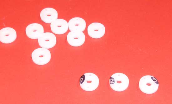
The first step is to gather up the #2 pistons. Seeing as the number is a bit hard to read, I used a Sharpie to highlight the numbers on all the pistons. Highlight, grab the 4 #2 pistons and trim off any excess plastic that sticks out off of them.
Step 2
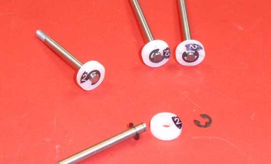
Snap an e-clip into the lower groove in the shock shaft, slide the piston into place and secure with a second e-clip.
Step 3
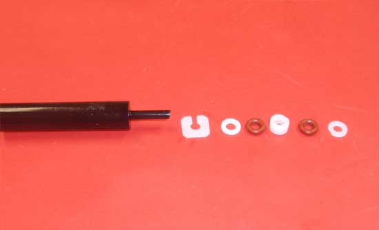
Before the easy-to-build shocks that are available today, most shocks were built by sliding the seals down into the bodies. Start this step by gathering up all the parts shown (x4, since we’re building 4 shocks) and make sure you trim any spare plastic ‘burrs’ hanging off the parts. Slide the parts onto the shock tool in the order shown.
Step 4
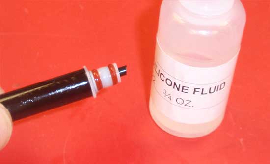
Using the silicone fluid included with the kit, put a drop or two on the assembly, making sure to coat all sides of the parts.
Step 5
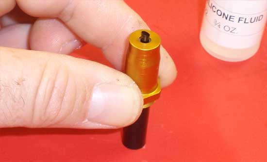
Slide the shock parts into the shock body, place the tool on a flat surface and press down on the body as shown. You should hear (and feel) the body ‘snap’ into place. You can also tell the parts are seated by how far the shock tool sticks out of the body (see pic). Build all 4 shocks.
Step 6
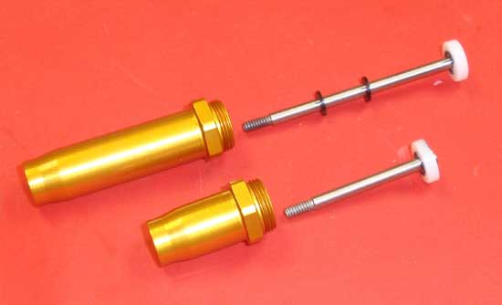
Take the shorter shock shaft assembly and put a drop of silicone fluid on the threads. Slide it down into the body and CAREFULLY push it past seals. Do the same for the rear shocks, but before pushing into the body, slide two down-travel limiting shim on the shaft first (2 on each rear shock shaft).
Step 7
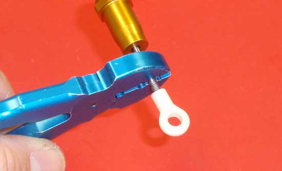
Grab ahold of the shock shaft and thread the plastic eyelet onto the shaft just to where the threads disappear. I use a STRC Shock Shaft Holding Tool as it allows a firm grip but doesn’t scratch the shock shaft.
Step 8
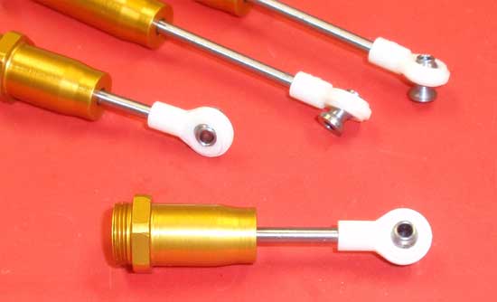
Pop the shock pivot ball into the eyelet as shown. Once completed, your shocks should look like this.
Step 9
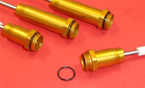
Take a black o-ring and feed it over the shock body as shown.
Step 10
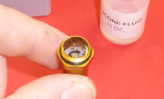
Fill the shock with the provided silicone oil. Move the shock shaft slowly up and down to release any air bubbles under the piston. Set the shock aside to allow the bubbles to rise to the top. Continue the other 3 shocks.
Step 11
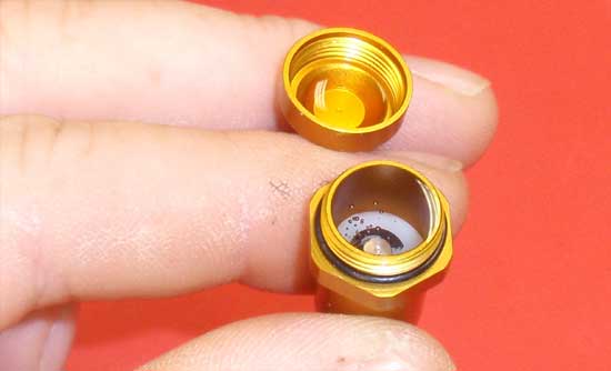
Once the bubbles are gone, fill the shock back up to the top (i usually fill it until it is perfectly flat across the top of the shock body). Put one drop of oil in the cap, flip it over onto the shock and tighten down. You’ll want to follow the shock bleeding instructions in the manual. Once completed, the shock shaft should push all the way up into the body.
Step 12
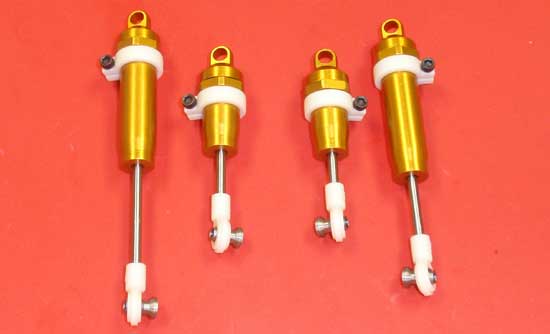
Install the screw into the shock collar, slip the collar onto the body and tighten down the screw. Move them all the way to the top to start. Notice how I have two collars with the screws on one side, two with them on the other. This will make it easier to adjust when on the car.
Step 13
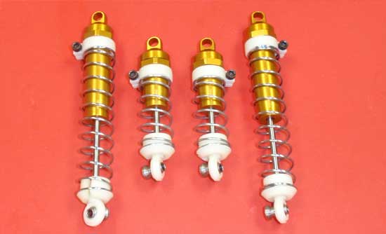
Slide the springs onto the shocks followed by the spring cups (at the bottom). At this time, you can also match the shock collar setting to the ones listed in the manual.
Step 14
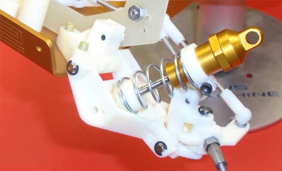
This part can be a little tricky as there the tolerances for the bottom of the shock slipping into the suspension arm are quite tight. I took an Xacto and trimmed a little plastic away from the arm, beveling the entry point for the bottom of the shock. This helped it to slide into place much easier.
Step 15
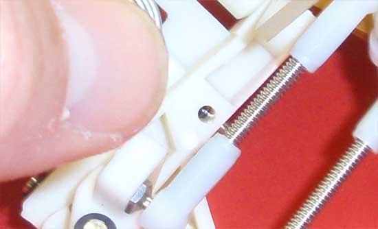
The lower shock pin get installed next, but before I did that, I took my Sharpie and colored in the set screw groove on the pin. Now, when I slide it into the arm, I can see the black through the set screw hole, helping me align these two parts easier.
Step 16
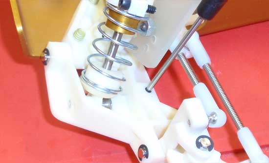
Install and tighten down the set screw.
Step 17
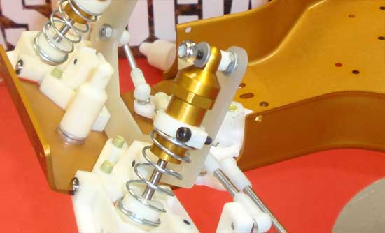
Slip the shock bushing onto the screw followed by the shock. Set the aluminum washer into place and secure the whole assembly with the locknut.
Step 18
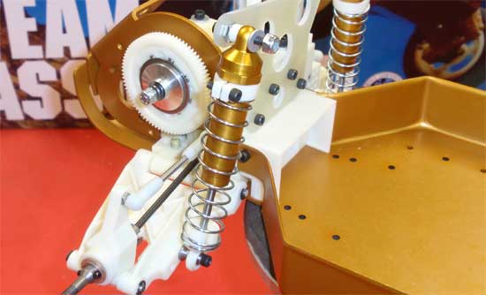
Insert and tighten the screw into the bottom of the shock (2nd hole in). Slip the shock bushing onto the screw followed by the top of the shock. Set the aluminum washer into place and secure the whole assembly with the locknut.
Team Associated RC10 Classic Online Build – Part 6
In Part 6 of our build, we’ll work on installing the electronics. Even though this is a vintage build, we won’t be installing vintage electronics. The RC10 Classic will be getting a full range race-spec XP, LRP and Reedy equipment to get ‘er up and going with the least amount of headaches.
Build Notes:
• Have a soldering iron handy for this step. You’ll need to attach the ESC wires to the motor and solder plugs to the battery wires.
• The steering setup is like the original but can be reworked to use a turnbuckle if you wish.
Step 1
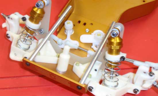
Yes, this first step has nothing to do with the electronics, but it also has nothing to do with the shocks (which we built and attached in the last step). Anyway, take a sec and install the two nose tubes as shown. Make sure you install the shorter screws in the sides of the chassis and the longer ones through the front. A dab of threadlock here will help keep the screws from backing out.
Step 2
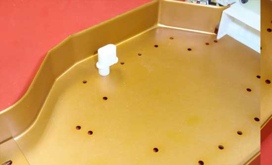
Next, install the antenna mount…
Step 3
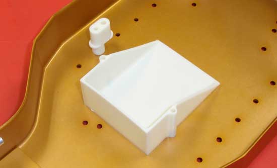
…followed by the battery cup…
Step 4
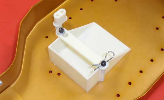
…following that by the battery strap. Note the orientation of the strap, and don’t forget to install the aluminum washer.
Step 5
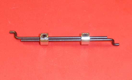
The steering linkage is next. It’s easier to assemble than it appears…just build it like the picture. I wouldn’t worry about the threadlock just yet as we’ll need to loosen those set screws again shortly.
Step 6
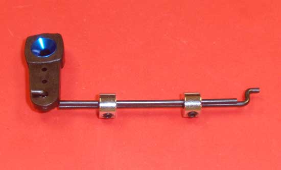
Once built, feed one end through the servo horn as shown. You may need to open up the hole in the horn a bit to get the linkage through.
Step 7
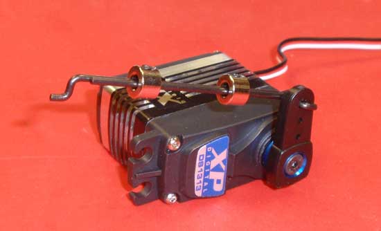
Attach the horn to the servo using the servo-supplied screw. Your assembly should look like this. For this build we are using one of Team Associated’s XP servos; the DS1313.
Step 8
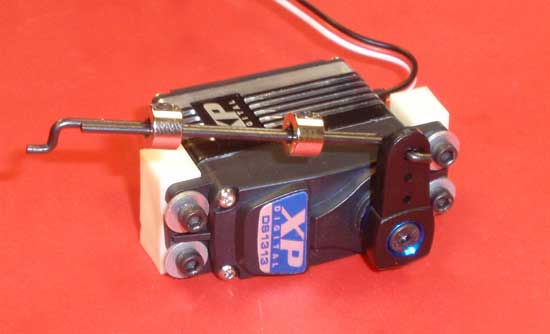
Attach the mounts to each side of the servo but do not tighten all the way yet.
Step 9
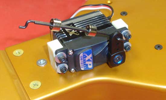
Because mounting the servo in the car makes it difficult to tighten up the mount screws (or line up the mount holes through the chassis), we always mount the servo to the bottom of the chassis first. This allows us to line up the servo mount holes with the chassis and then tighten the screws that hold the servo to the mounts.
Step 10
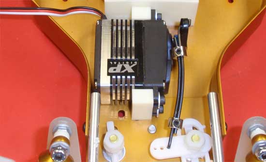
Remove the servo from the bottom of the chassis and install correctly. You’ll want to slide the other end of the steering linkage into the servo saver prior to mounting the servo to the chassis. Also, you might notice that my linkage is bent. This helps it clear the servo when it’s at full lock. You may have to do something similar if your linkage hits the servo.
Once mounted, turn the servo horn until it is 90 degrees straight up. If your front tires are pointing straight ahead, you’re good to go. If not, loosen the set screws on the linkage and ‘slide them apart’ to adjust. Once in position, you can put a tiny dab of threadlocker onto the setscrew and tighten them down.
Step 11
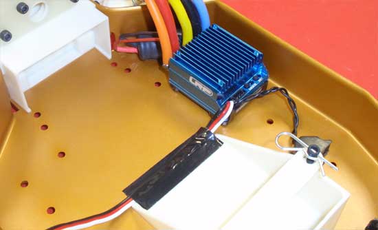
Install the ESC on the right side of the chassis as shown. Since I’m running the ESC lead under the battery, I added a small piece of black tape to hold it in place. For this build we are using LRP’s awesome Flow WorksTeam Brushless ESC.
Step 12
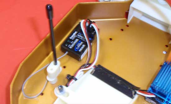
The Futaba 4PLS reciever gets mounted on the left side. Feed the antenna through the mount and tube. Plug the ESC and servo leads into the receiver.
Step 13
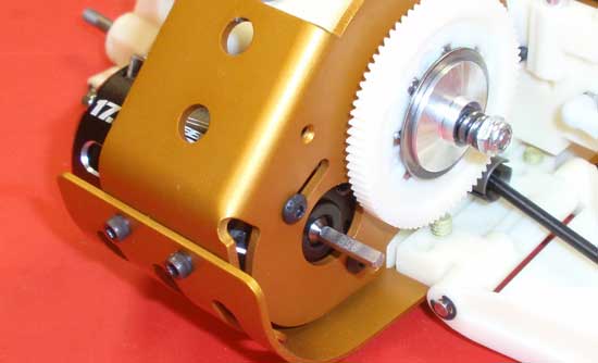
Slide the Reedy Sonic 540 17.5T Spec Brushless Motor into place and attach with the 3x6mm screws.
Step 14
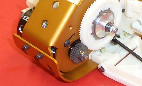
Attach the pinion, set the gear mesh and tighten down the 3x6mm screws.
Step 15
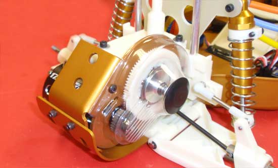
Attach the gear cover and dust plug.
Step 16
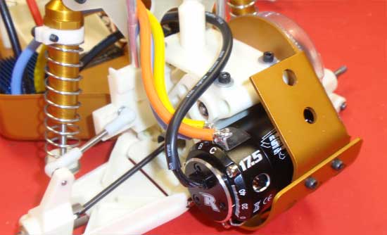
Wire up the ESC wires to the motor and attach the sensor wire. If you feed them through the fiberglass shock tower, you might want to sand the edges slightly to avoid cutting the wires.
Step 17
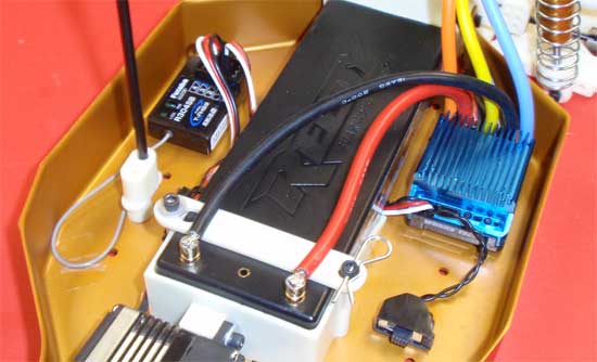
Install the battery and plug it in! This is a good time to give it a test to make sure everything is working.
Team Associated RC10 Classic Online Build – Part 7
The wheels and tires on the RC10 Classic are excellent reproductions of the original set. These tires were molded by Proline and are a little softer than the originals. I’m happy to see that AE even included the cool plastic knock offs.
Build Notes:
• While the screw-together wheels are good for slower motors, anything faster will probably blow them apart. If you’re going to run a hotter-than-stock motor, I would suggest gluing the tires to the wheels after you’ve assembled them.
Step 1
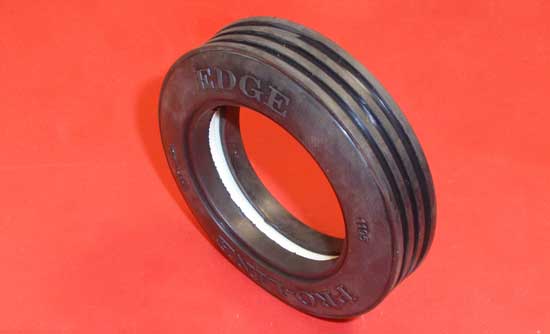
Our first step is to install the plastic insert into the tire as shown.
Step 2
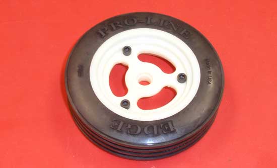
Press the rear half of the beadlock wheel into the backside of the tire and the front half of the beadlock wheel to the frontside of the tire. Secure with the 3 4-40 screws. Be careful not to overtighen these screws!
Step 3
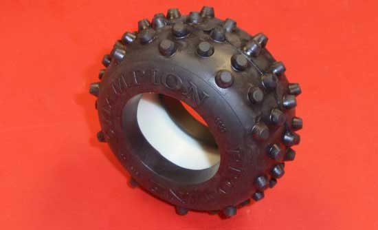
Install the plastic insert into the rear tires.
Step 4
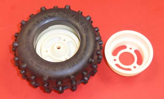
Press the rear half of the beadlock wheel into the backside of the tire and the front half of the beadlock wheel to the frontside of the tire. I installed the ‘optional wheel insert’, however I’m not sure if it is needed with these tires.
Step 5
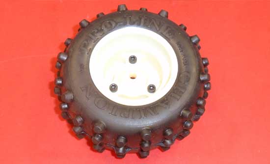
Secure with the 3 4-40 screws. Be careful not to overtighen these screws!
Step 6
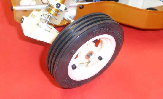
Press one of the flanged Oilite bushings into the front and backsides of the front wheels and slide onto the axle. Racers might want to install the 4-40 locknut, but I prefer the cool plastic knock offs. After tightening down, check to make sure the tires spin freely. If not, back the wheel nut off slightly.
Step 7
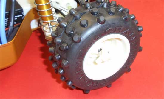
Slide the rear tire assembly on, making sure the pin in the axle lines up with the slot in the rear wheel. Tighten down whichever wheel locking choice you’ve picked.
Team Associated RC10 Classic Online Build – Part 8
The final step in the RC10 build is the body. I decided to have the body painted in Jay Halsey’s World Championship colors…but with a slight 2013 twist. Larry Genova did it up complete with the driver and gave me exactly what I was looking for…again! The car looks great especially with the lights attached.
Build Notes:
• It is suggested that you mark the bodymount holes prior to painting. That will make it much easier to mount. Don’t forget to mark the wing mount holes as well.
Step 1
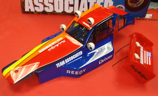
The first step of the final step is to cut out the body and attach the lights. A tip: don’t make the holes for the light screws too big. In fact, it’s better if you make a tiny hole and test fit. The screws have a tiny head and if you make the holes to big, the screws will pull through the body. You should also put a tiny drop of threadlock on the screws to help lock them in place.
Step 2
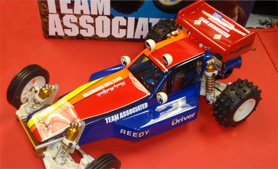
A final look at the RC10 Classic. The body and wing have been cut and mounted and the buggy is ready to go! Next step…the test drive!
Thanks for following along the build. If you were lucky enough to get one of these cars, take good care of it…it’s a Classic.

