

Team Associated T5M Online Build
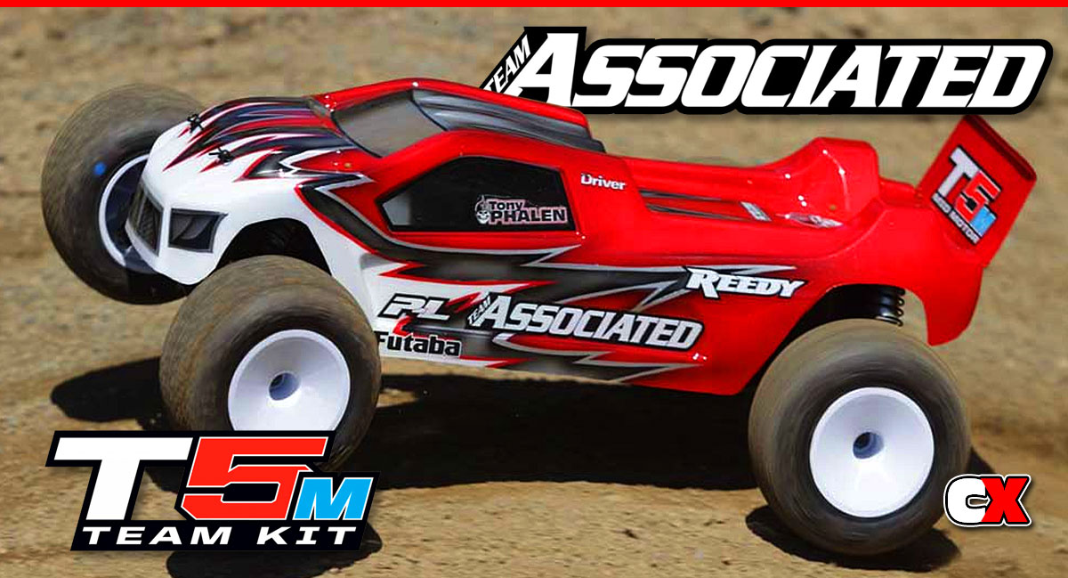
It was only a matter of time until the brilliant mid-motor design of Team Associated’s B5M made its way to their Stadium Truck. This truck features all of the same goodness as the buggy but in a longer, wider form. It’s handling is excellent and it jumps like a gazelle, making it one of the best Stadium Trucks I’ve ever driven.
While the build is very similar to that of the B5M, we thought it deserved its own build simply because it’s just that good.
Team Associated T5M Online Build – Part 1
The first part of our Team Associated T5M build revolves around the steering. This ST features a bearing-supported, dual-bellcrank steering system that includes tuning features like Ackermann, bumpsteer and and toe.
Build Notes:
• In the later steps you may notice that I highlighted the molded lettering on the bulkheads with a silver Sharpie. This makes it much easier for me to identify which bulkhead I’ve installed; either the 25° or 30° part.
• The bearings for the entire kit come in one bag, so open the bag, get what you need for this step and set the other aside.
• Step 5 has you assembling with 22mm screws, per the manual. There were no 22mm screws in my kit, only 24mm ones. I used these without any issues.
Step 1
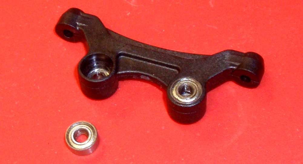
Start Part 1 by installing the 4 bearings into the steering rack.
Step 2
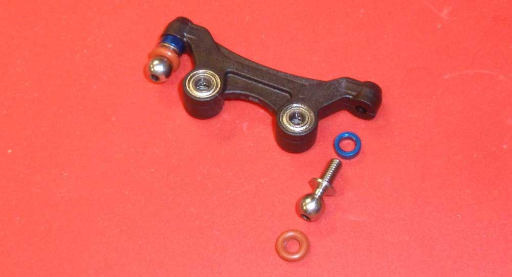
Next, slide a 2mm washer over the heavy duty ballstud and assemble. Slip a red o-ring over both ballstuds. This helps remove any slop the steering might have.
Step 3
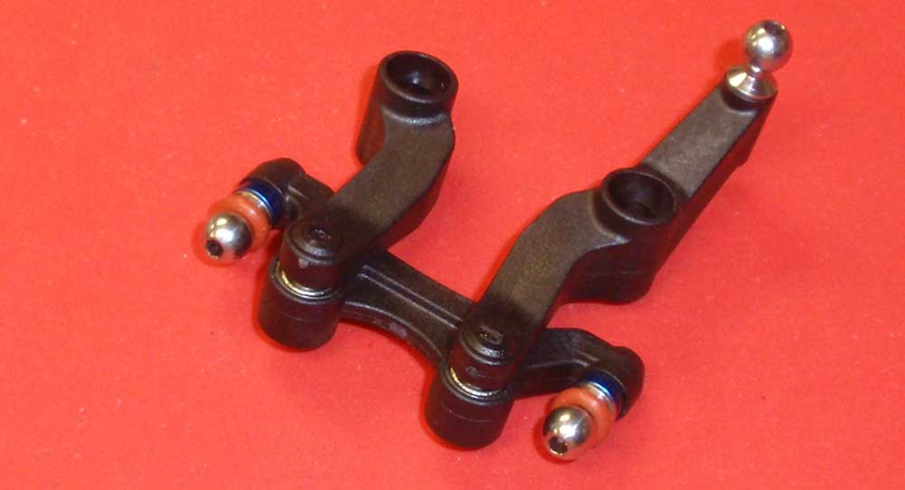
Attach the bellcrank arms to the steering rack as shown. Do not overtighten these screws; the bellcrank arms must move back and forth smoothly and without bind.
Step 4
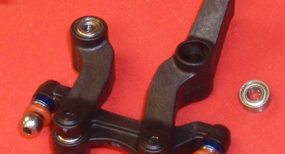
Insert 4 more bearings into the bellcrank arms.
Step 5
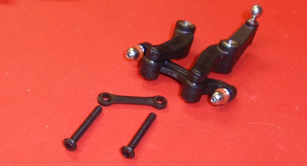
Before assembly, look closely at the bellcrank brace. You’ll notice one side is flat, the other has a slight lip on it. This lip needs to face the bearings during assembly. So, slide the 2 24mm screws (see Build Notes above) through the bellcrank brace and up through the bellcrank arms.
Step 6
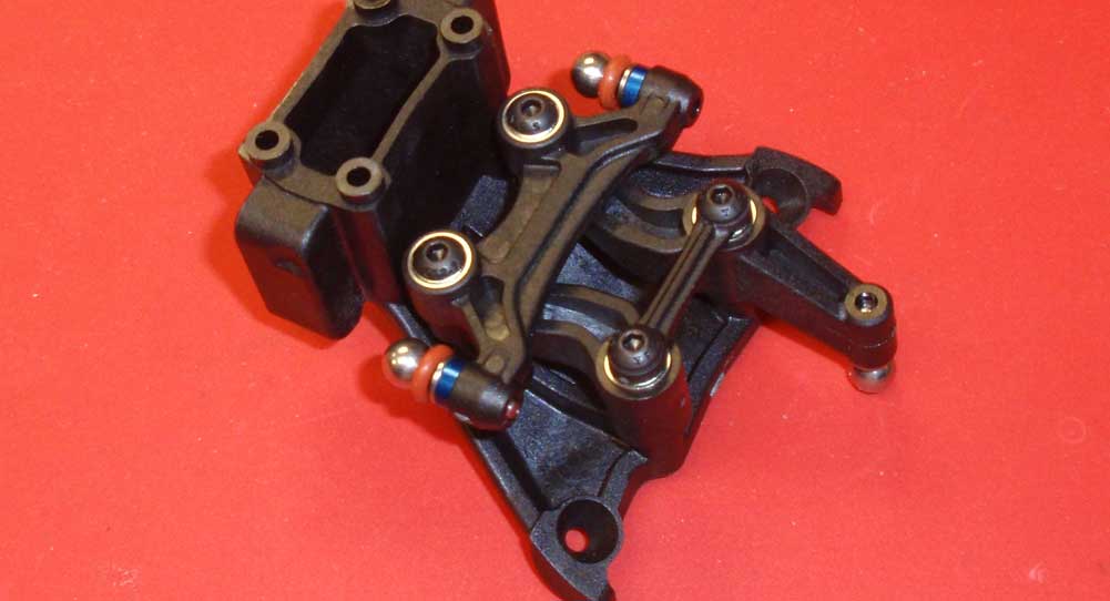
Attach the steering assembly to the top plate. I found it easier to flip the top plate over and attach as shown. Do not overtighten; everything needs to swing freely.
Step 7
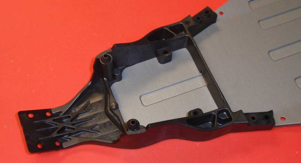
Attach the front chassis plate to the chassis.
Step 8
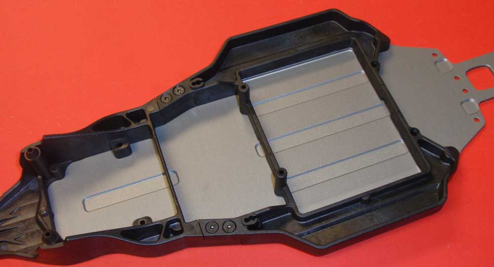
Attach the center chassis plate to the chassis.
Step 9
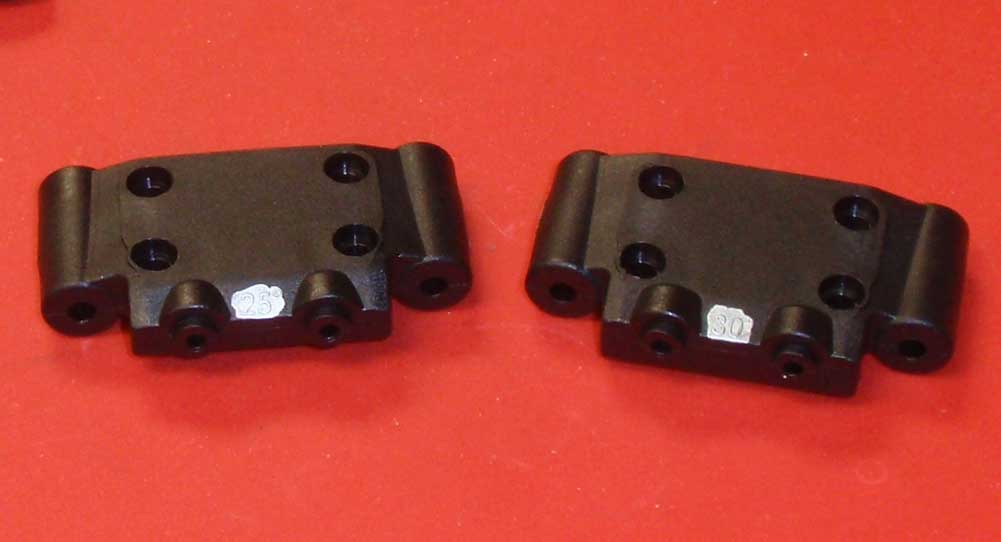
Here are the 2 front bulkheads AE has supplied with the T5M. As mentioned in the Build Notes, I used a silver Sharpie to highlight the number for easy reference. The manual suggests using the 25° bulkhead (or 25° Kickup) during the build, so that’s what we did. You can read up a little more on Kickup on our RC Tuning Guide page.
Step 10
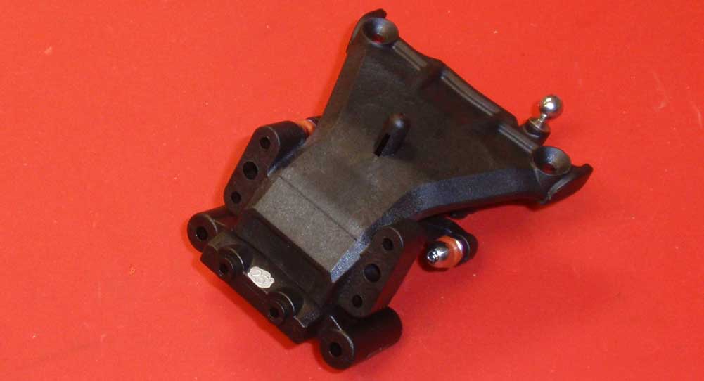
Assemble the bulkhead and top plate. They are a press-fit so they should stay together easily.
Step 11
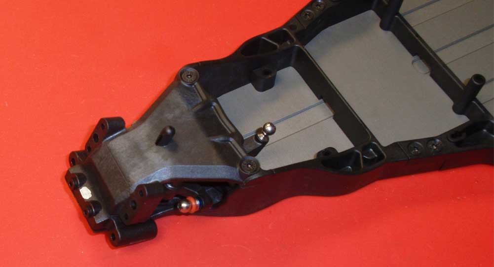
Attach the top plate/steering assembly to the chassis. Swing the steering assembly back and forth a few times to make sure there is no binding in the system.
Great job!
Team Associated T5M Online Build – Part 2
The front suspension is pretty straight forward and includes quite a bit of tuning. AE has opted to use inserts to adjust alot of the front end, including caster and axle location.
Build Notes:
• We used, once again, the silver Sharpie to highlight the parts steering block and caster block inserts in this step.
Step 1
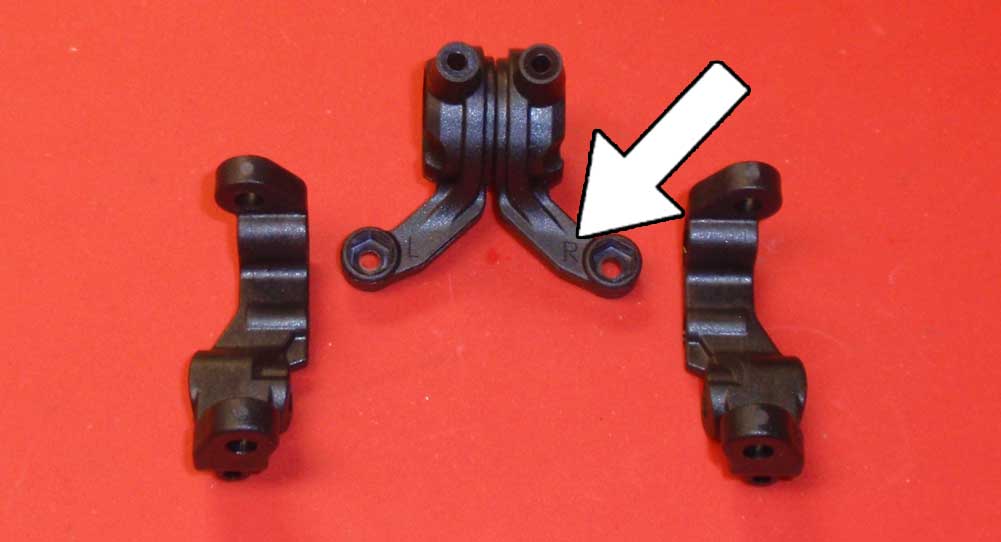
Before we start assembly, get familiar with the left and right parts being used. The caster blocks are obviously different, however the steering blocks have a small L and R molded into them (see the arrow). I would suggest keeping the left and right parts together but separate on your bench so you don’t mix them up.
Step 2
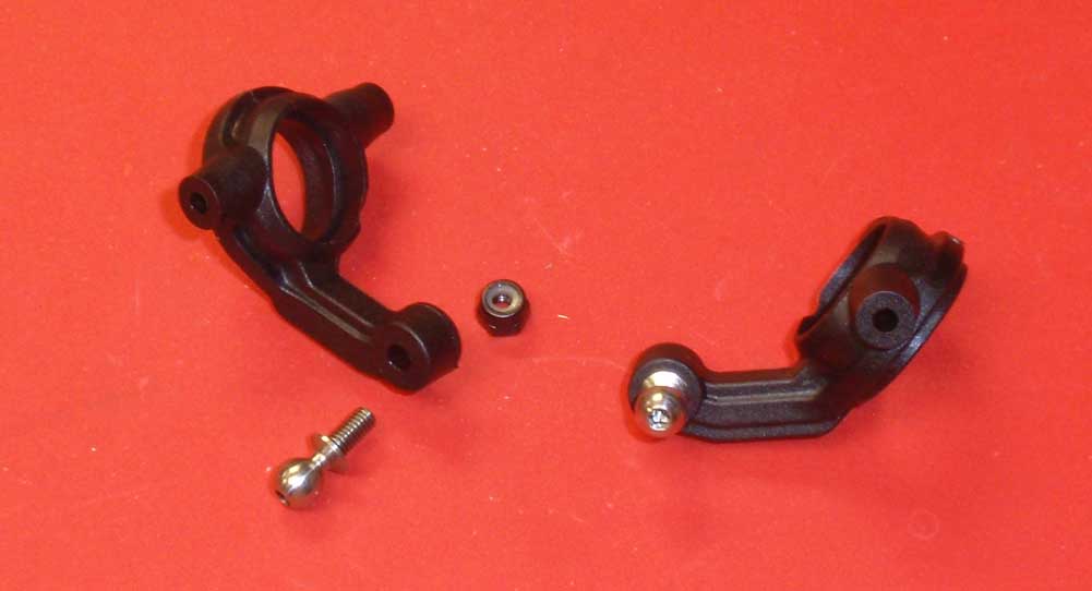
Install the heavy duty ballends into the steering blocks, using the M3 locknut to keep them in place.
Step 3
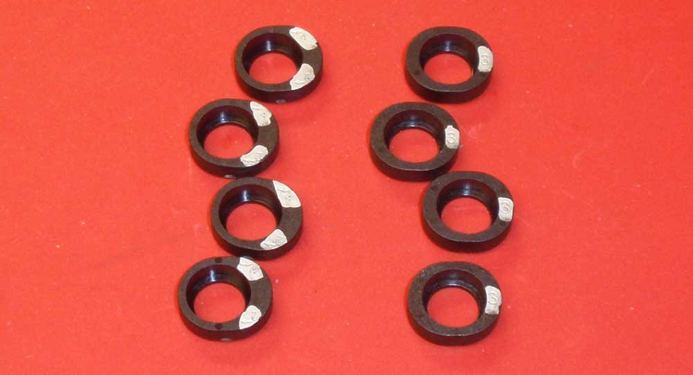
A look at all of the steering block inserts, Sharpied up for easy reference. We’ll be using the 2/4° trailing insert for this build (set to 4°).
Step 4
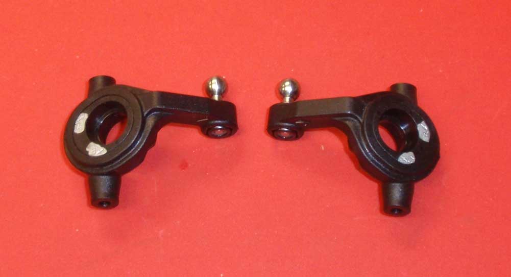
Press the inserts into the steering blocks, making sure the highlighted area, or 4° arrow, is facing away from the ballstud as shown.
Step 5
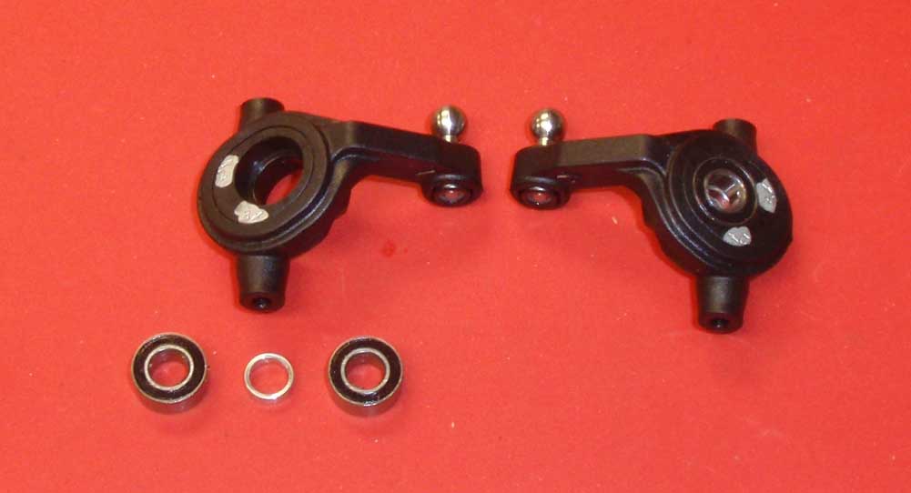
Install the bearings with the aluminum crush washer in between.
Step 6
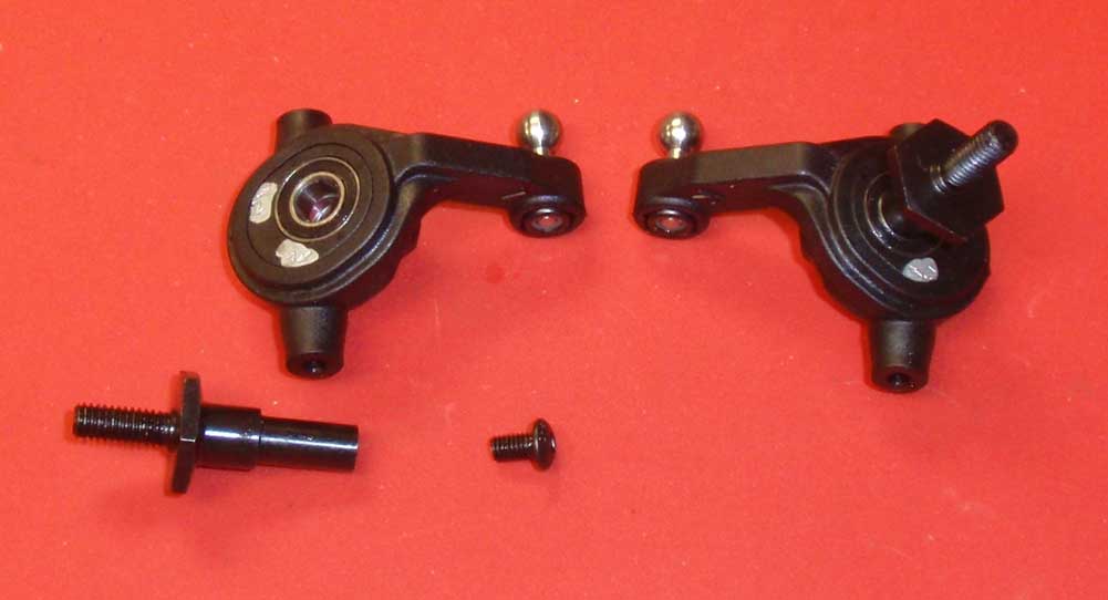
Insert the T5 axles through your bearing assembly and secure with the 5mm screw. A light dab of threadlocker is suggested here to keep the screw from backing out.
Step 7
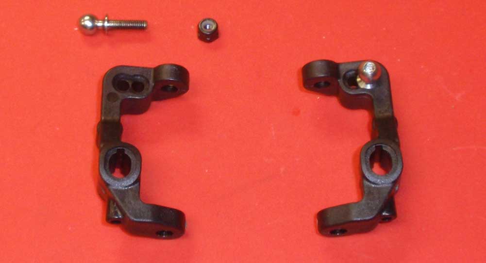
Install the heavy duty ballstuds into the caster blocks, using the M3 locknut to secure. Note the orientation of the blocks.
Step 8
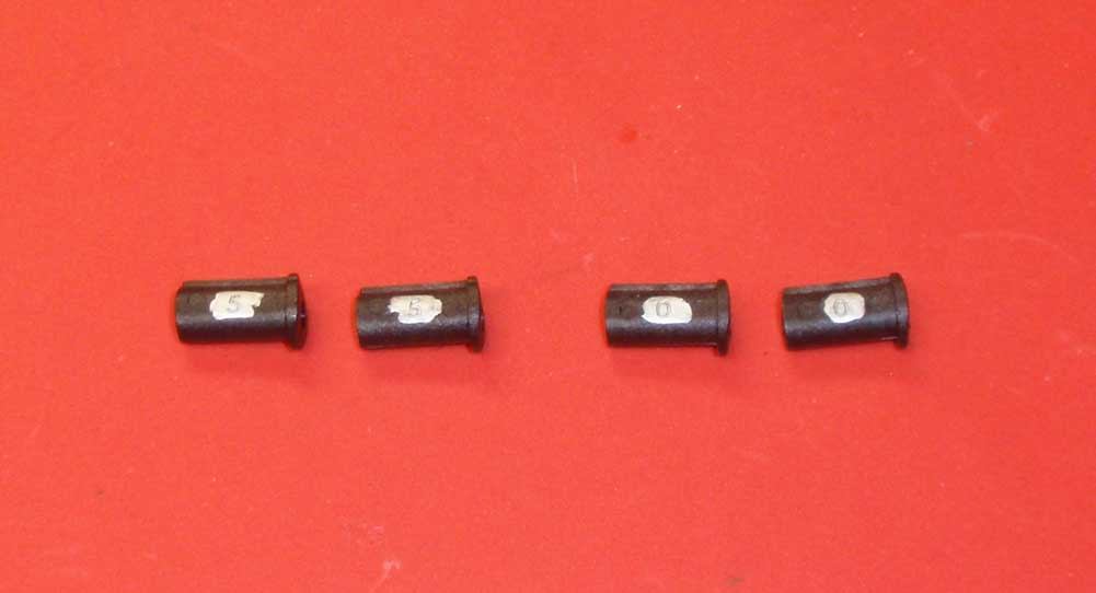
The T5M comes with 2 inserts; a 0° and a 5°. We’ll be using the 5° per the manual, highlighted for easy reference.
Step 9
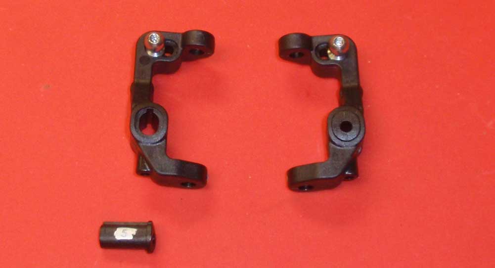
Install the caster inserts. Note the orientation of the caster blocks.
Step 10
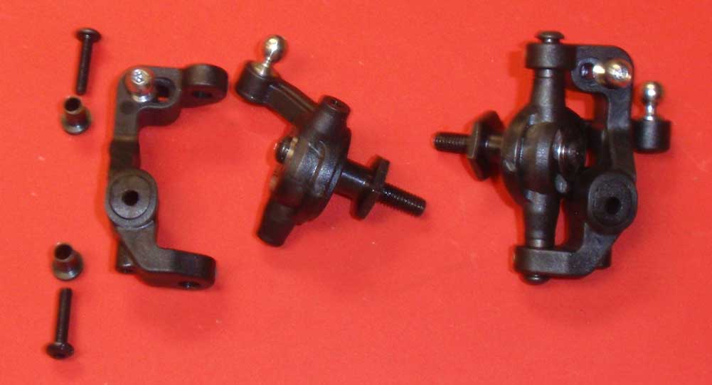
Time to mate the steering blocks with the caster blocks. First, make sure you have the left steering block attaching to the left caster block. Slip the caster block bushings into the caster block, then slide the steering block into place and secure with the pair of 12mm screws. SLOWLY tighten all the way down, then backing off about 1/8 of a turn. Test the steering block; if it feels tight, back the screws off another 1/8 of a turn and re-test. You want the screws tight without hindering the swivel movement of the steering block.
Step 11
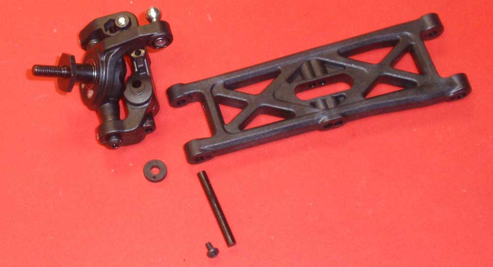
The T5M uses the same front arms on both the left and right of the truck. Note the orientation of the suspension arm, then insert the hinge pin through the arm, then the plastic spacer and then the steering assembly. Secure the pin with the 4mm screw.
Step 12
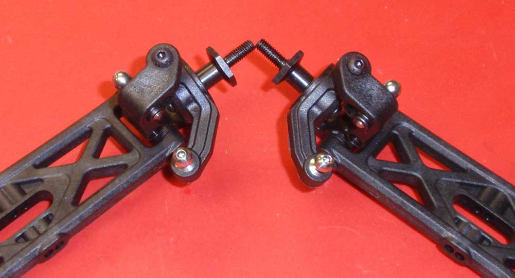
After assembly, your suspension arms should look like this.
Step 13
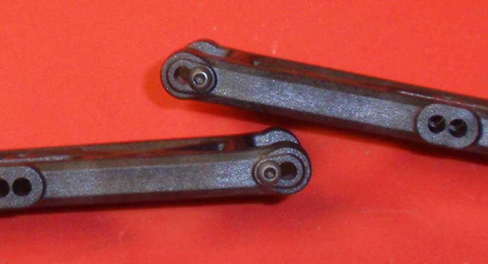
Now to attach the arms to the chassis. Start by installing the 4mm hinge pin retaining screw as shown.
Step 14
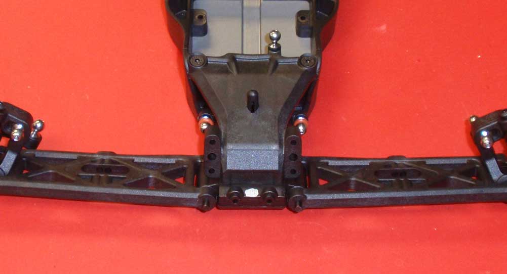
Slip the suspension arms around the front bulkhead and slide the long hinge pins into place.
Step 15
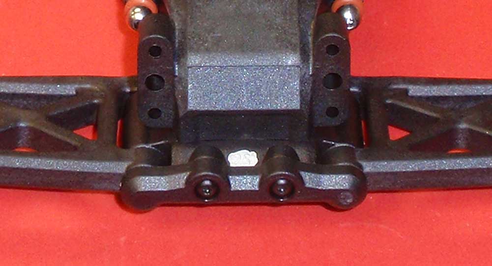
Attach the hinge pin brace. Give the front arms a quick swivel to make sure they move freely. If not, turn the truck up on its end and tap lightly on the suspension arm. Sometimes things are a little tight and need a little massaging.
Step 16
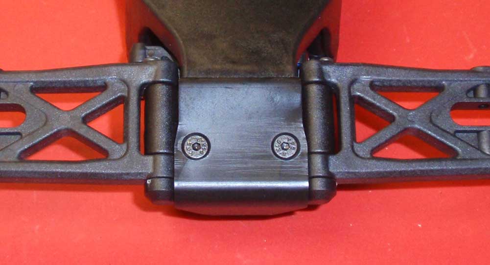
Flip the T5M over and attach the front bumper.
Step 17
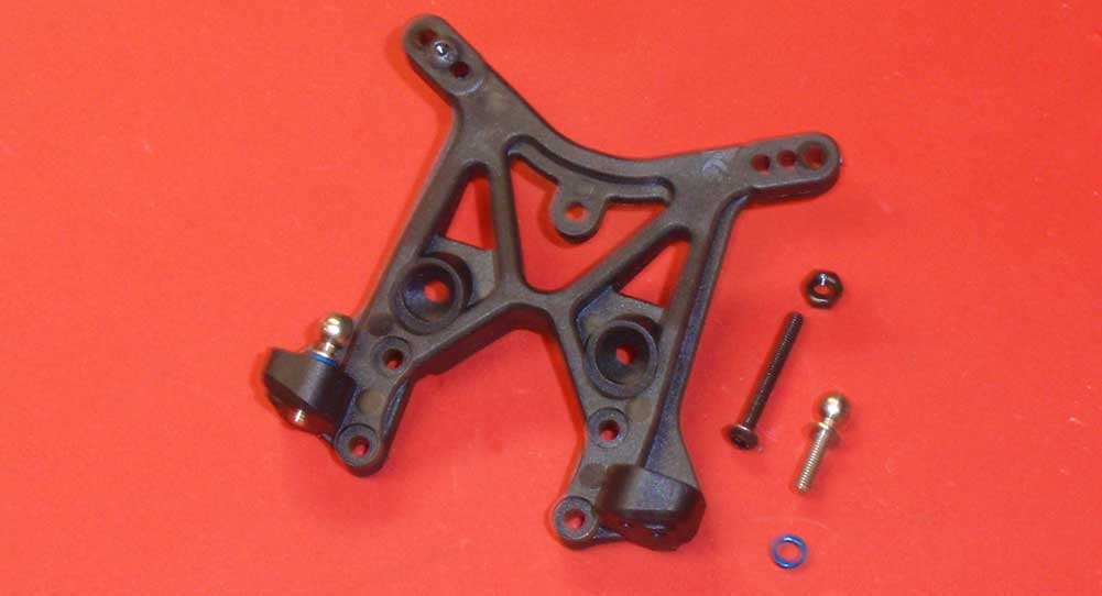
Assemble the front shock tower using the middle hole for the upper shock mount and the inside hole for the camber link mount.
Step 18
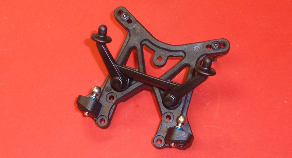
Attach the front body mount to the tower.
Step 19
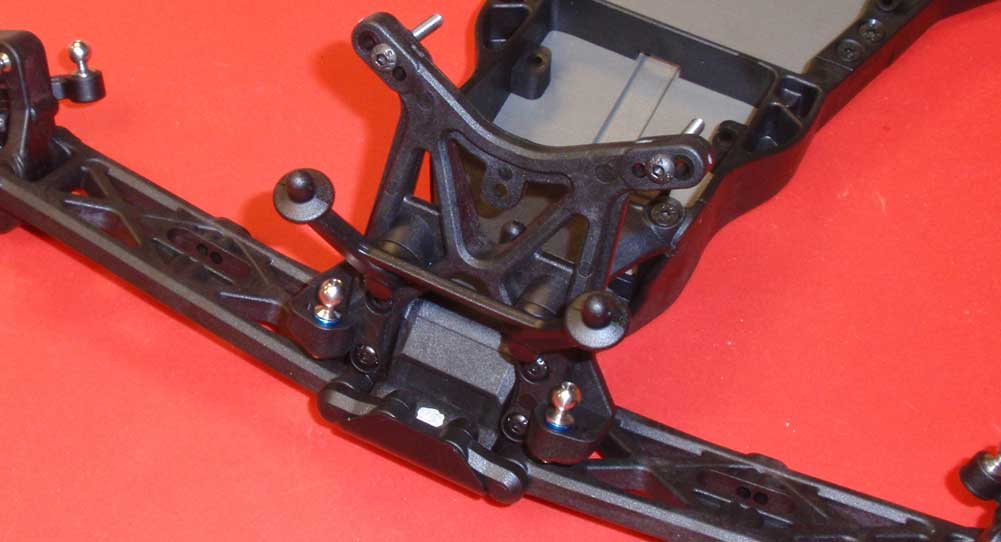
Attach the assembled shock tower to the front bulkhead.
The front suspension is done and looking good.
Team Associated T5M Online Build – Part 3
The rear suspension on the Team Associated T5M is similar to the B5M and even includes a cool blue aluminum inner camber ballstud mount. This mount is reversible to allow different tuning and is a solid mounting point for the heavy duty ballstuds. AE has broken the rear build into 2 different parts, separating the build by the assembly of the transmission. So, this is Part 1 of the rear suspension build.
Build Notes:
• When you get to the aluminum rear ballstud mount, make sure you build it with the -2mm side up.
Step 1
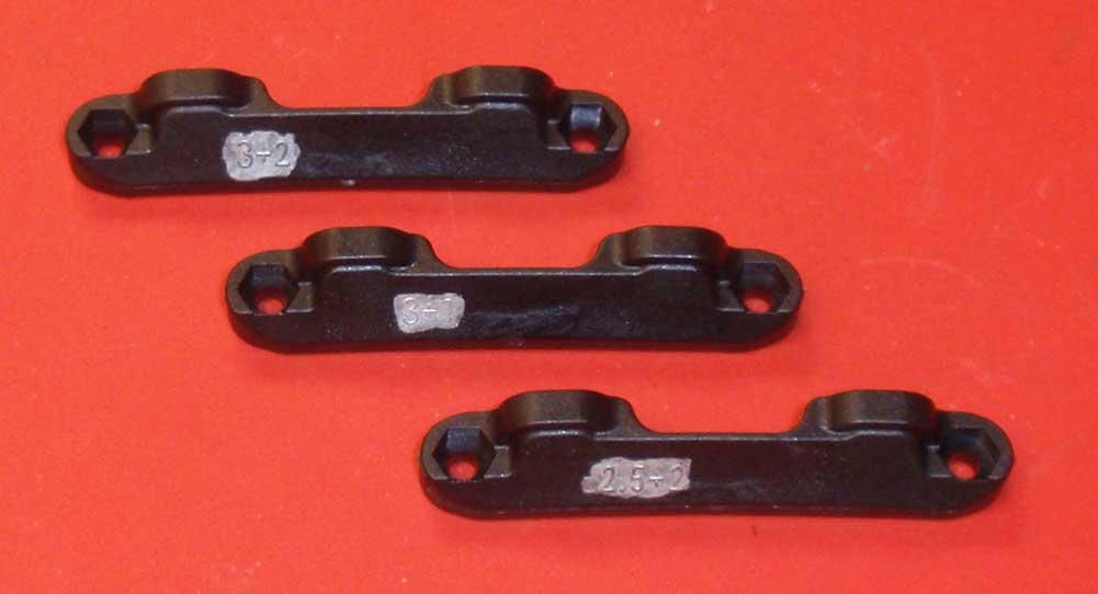
The T5M comes with 3 different C arm mounts; a 3+2, 3+1 and 2.5+2. These setting coincide with rear Toe and Anti-Squat, ie, a 3+2 is 3° of rear Toe (in) and 2° of Anti-Squat. We’ll be using the 3+1 per the manual. You can read more about Toe and Anti-Squat on our RC Tuning Guide page.
Step 2
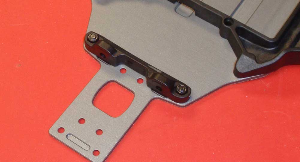
Attach the 3+1 C arm mount to the chassis.
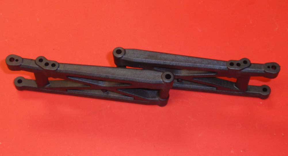
Step 3
Unlike the front, the rear suspension arms are not interchangeable. You’ll see from the picture that the lower shock mount holes predict which side of the car they mount to. The one on the left is for the left side of the T5M, the one on the right for the right side.
Step 4
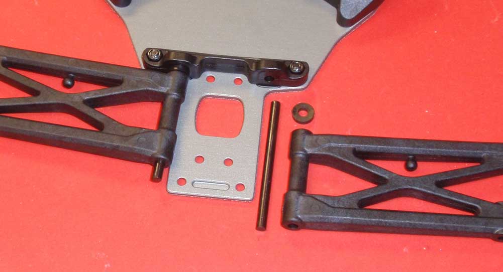
Insert the long hinge pin into the C arm mount. Slide a rear arm spacer into place followed by the suspension arm. Note the orientation of the arms.
Step 5
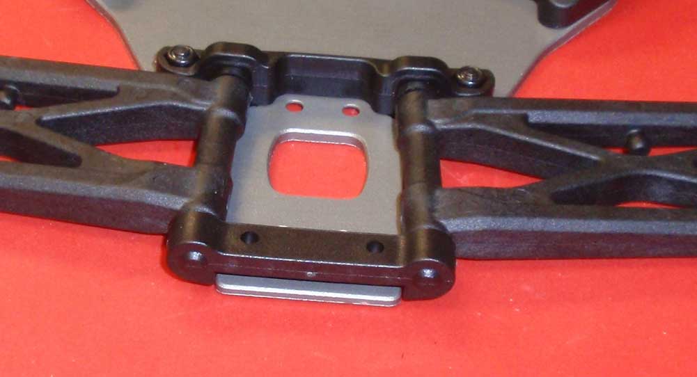
Slip the D arm mount into position. You may need to flex the hinge pins slighly to get the arm mount to fit.
Step 6
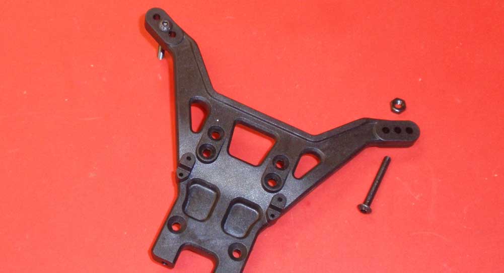
Assemble the upper shock mounts to the tower using the middle hole. Note the orientation of the tower.
Step 7
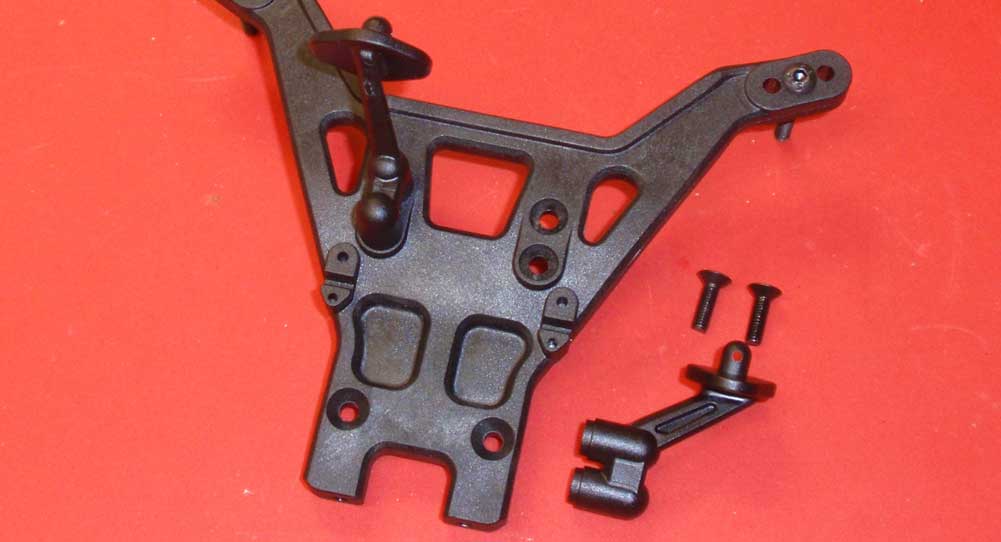
Attach the rear body mounts to the tower.
Step 8
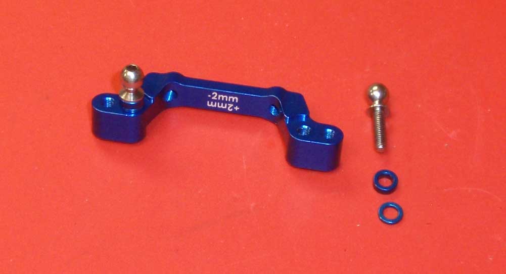
Assemble the rear camber link mount by installing the heavy duty ballstuds into the inner hole. Make sure you include a 1mm and 2mm washer.
Step 9
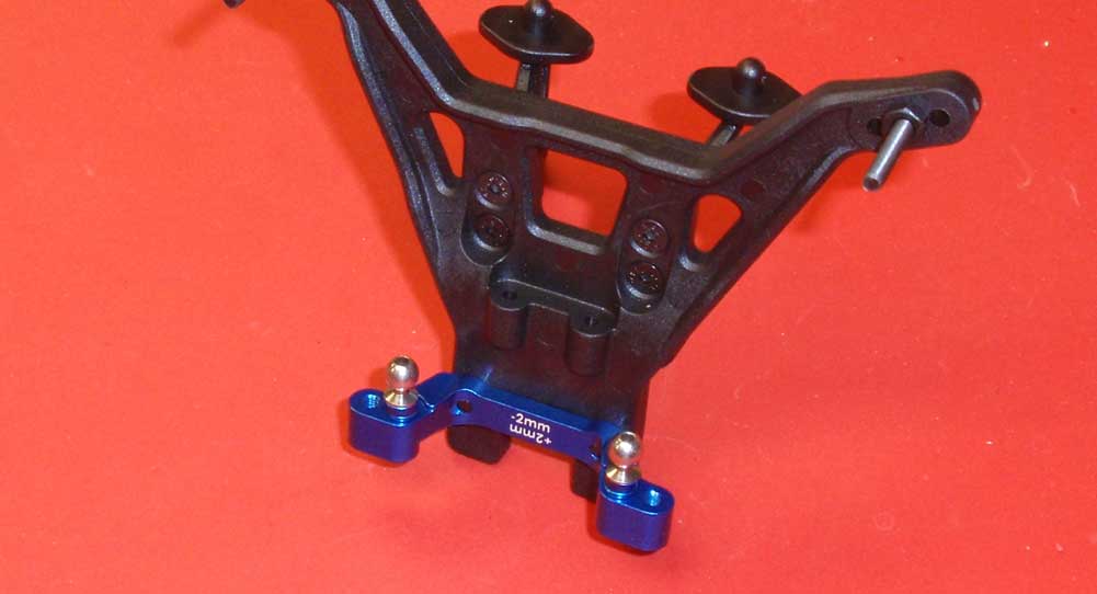
Attach the assembled rear camber link mount to the shock tower. A light dab of threadlocker is suggested here.
Step 10
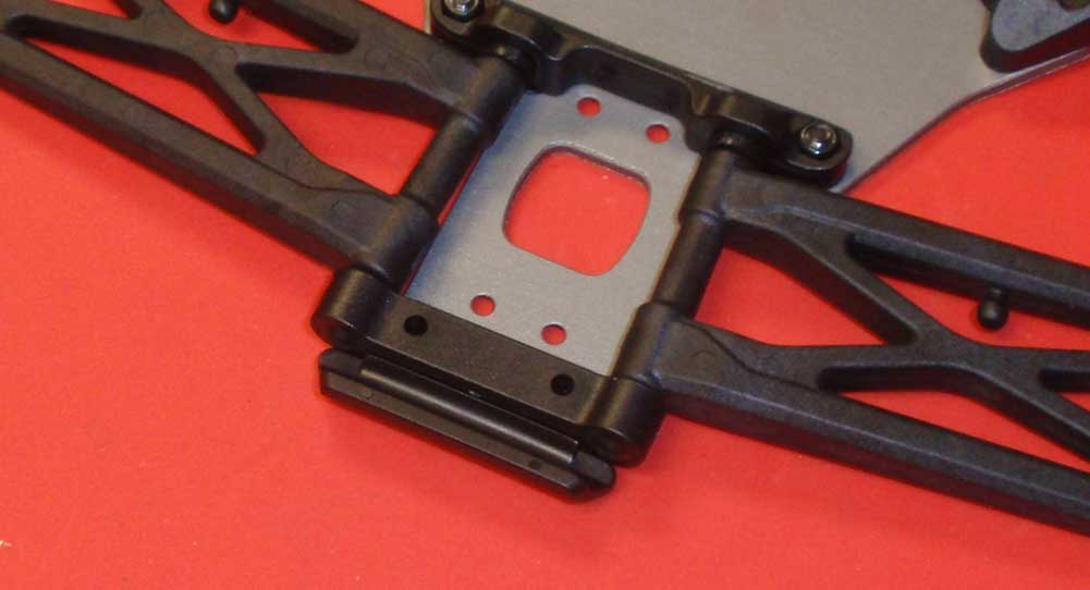
Slip the rear bumper inbetween the chassis and D arm mount.
Step 11
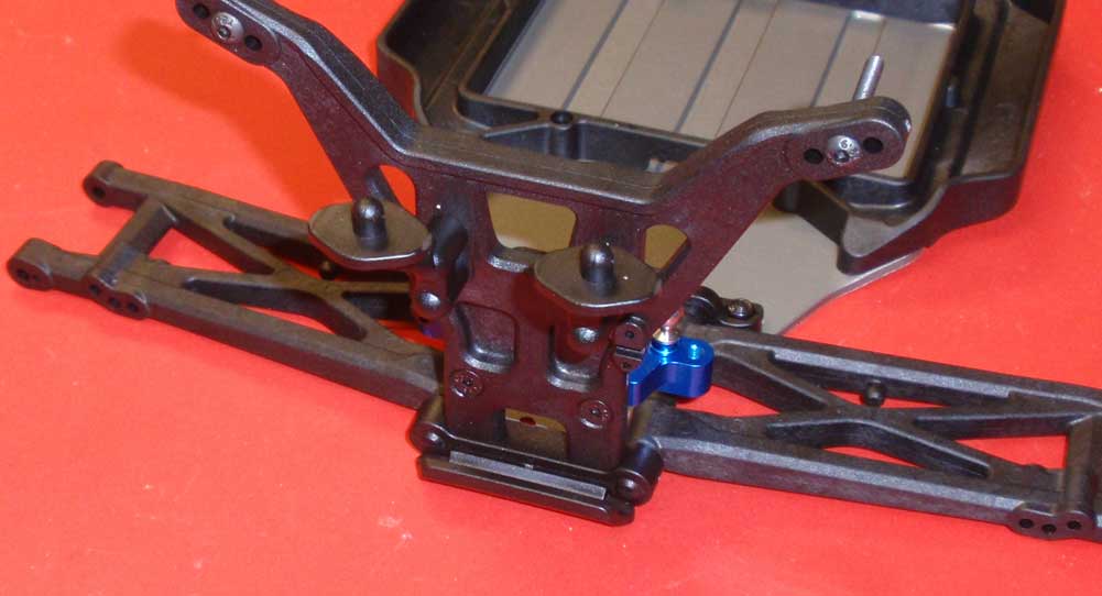
Slide the 18mm screws up through the chassis, bumper and D arm mount and use to secure the rear shock tower in place. Do this slowly to make sure the rear tower sets perpendicular to the chassis.
It’s starting to look like a truck now, right? Great job. Let’s get crackin’ on the transmission.
Team Associated T5M Online Build – Part 4
The Team Associated T5M comes equipped with the same stellar 4-gear transmission that you will find in the B5M. Thankfully it comes loaded with a ball diff (I’m not a gear diff fan), high-quality bearings and the A-Team’s V2 slipper clutch system.
Build Notes:
• Since we’ll be working with greases in this step, you’ll want to have a few clean rags handy.
Step 1
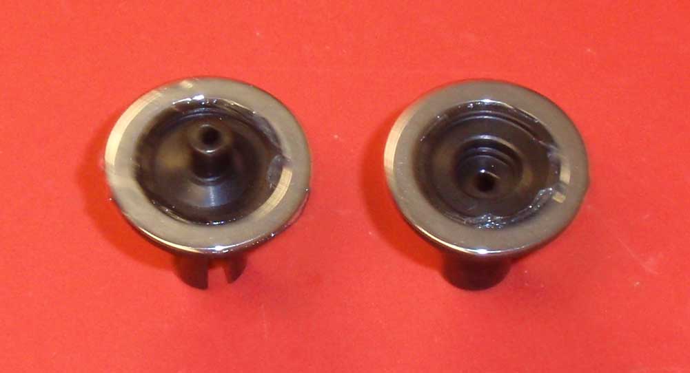
Let’s start by spreading a light coat of white grease onto the outdrives and setting the rings in place.
Step 2
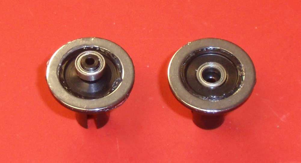
Place a 5×8 bearing onto each diff half.
Step 3
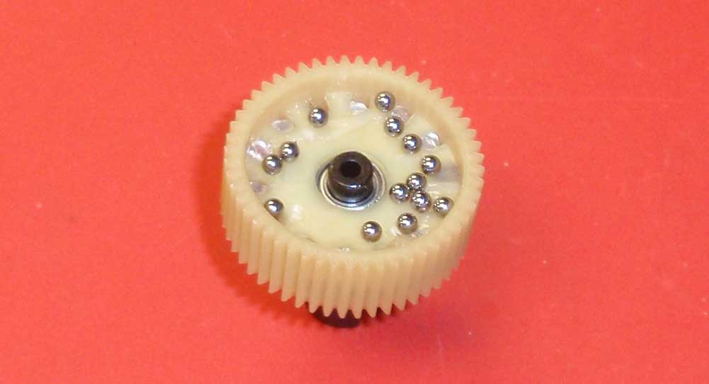
Set the diff gear onto the ‘male’ diff half side and press it over the bearing. Squeeze some white diff grease into each of the holes in the diff gear, making sure it actually makes it INTO the holes. Pour the carbide diff balls into the gear (as shown) and carefully press each one into a hole.
Step 4
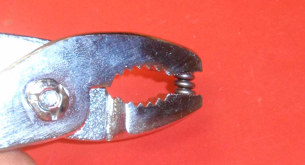
Pre-compress the diff spring. A couple good squeezes should do the trick.
Step 5
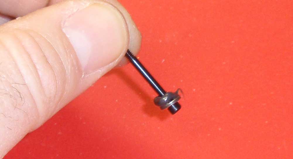
Slide a diff thrust washer over the diff screw and apply a bead of black grease to the inside of the washer.
Step 6
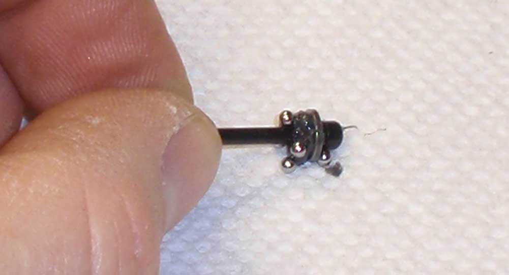
Pour the 5/64 thrust balls onto a clean paper towel. Carefully roll the diff screw assembly over the balls, letting the black grease pick the balls up.
Step 7
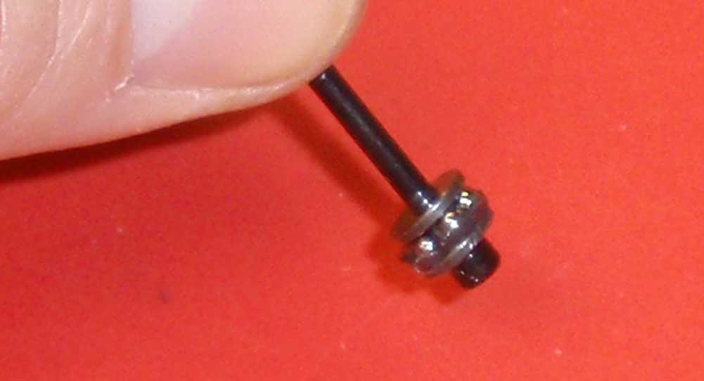
Slide the 2nd diff thrust washer into place and arrange all the balls into place. Your assembly should look like this.
Step 8
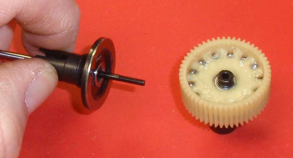
Slide the diff thrust screw assembly into the ‘female’ diff half and mate it to the ‘male’ diff half assembly.
Step 9
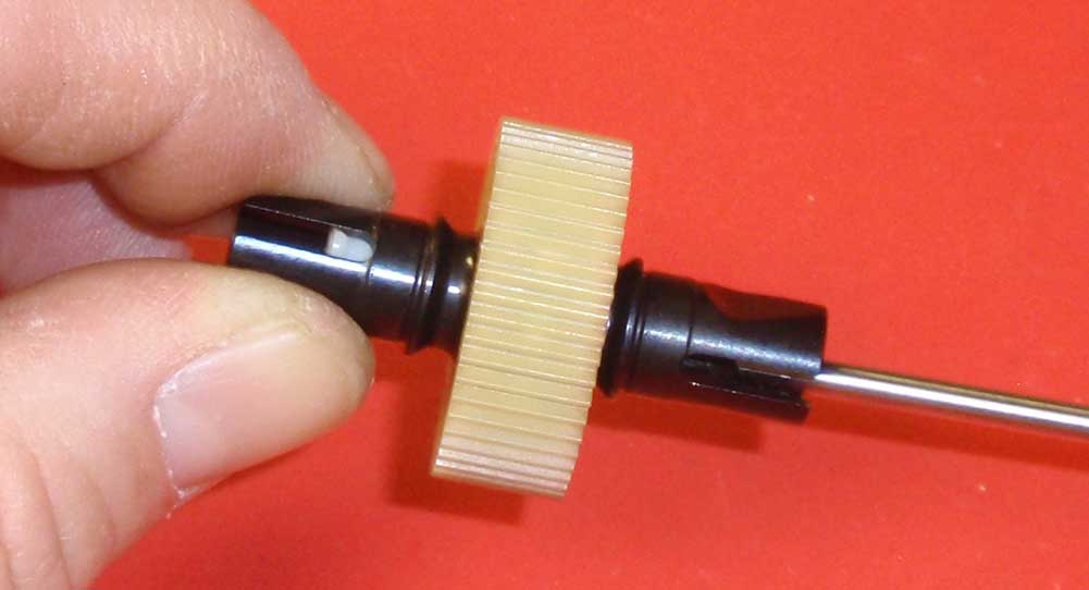
Drop the spring (from Step 45) and the locking t-nut into the diff half that is opposite of the diff thrust screw. Slowly tighten the screw until it has bottomed out, then back it off about 1/8 of a turn. During the tightening process, take a moment to ‘work’ the diff by rotating it a few times in each direction. This will ensure that everything seats properly.
Step 10
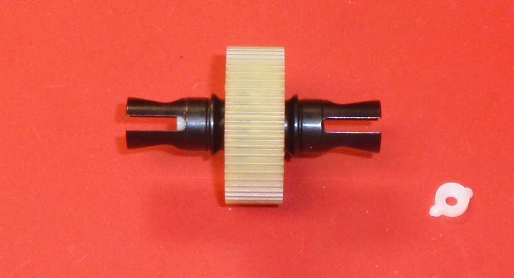
Once tightened, insert the diff screw cover into place.
Step 11
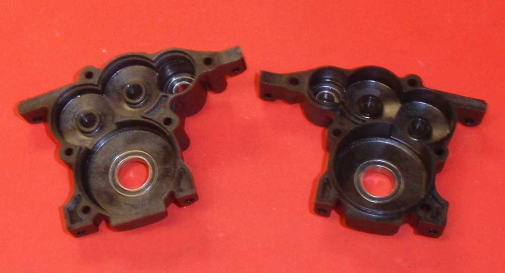
Grab both diff housing halves and insert the 10×15 lower bearings and 5×10 upper bearings. Press firmly to make sure they seat all the way.
Step 12
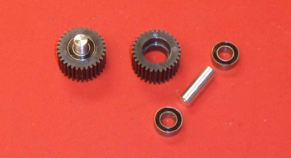
Assemble the 2 idler gears as shown.
Step 13
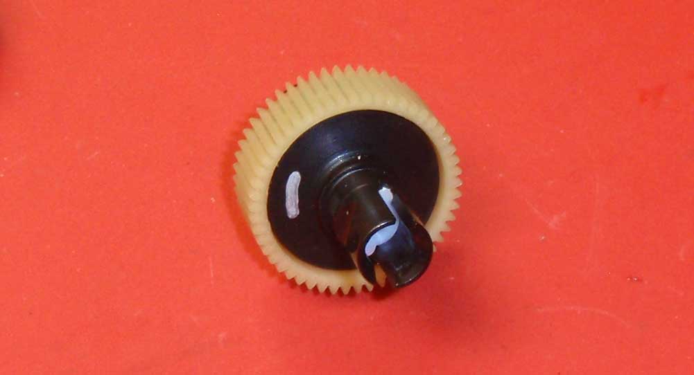
The assembled diff has to be inserted a certain way to ensure the screw doesn’t back out. To make it easier to see, I pulled out my trusty Sharpie and put a little-ish mark on the diff screw side. I guess a dot or something like that would have sufficed but, oh well.
Step 14
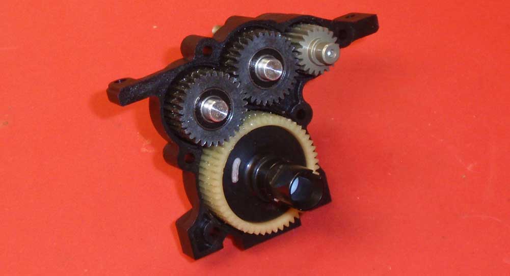
Insert the V2 top shaft into place, the 2 idler gears and the diff gear with the diff screw (or silver mark) facing out or away from the spur gear.
Step 15
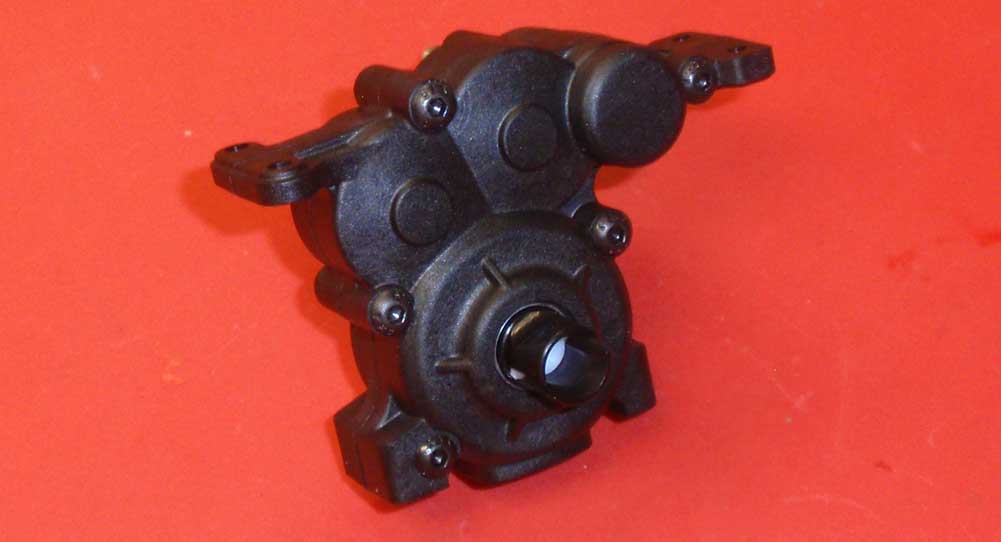
Align the other gearbox half and screw together.
Step 16
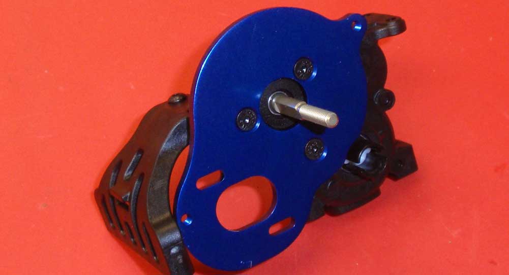
One of the nicest changes from older vehicles is the separate motor mount plate! Attach this and the chassis brace to the gearbox.
Step 17
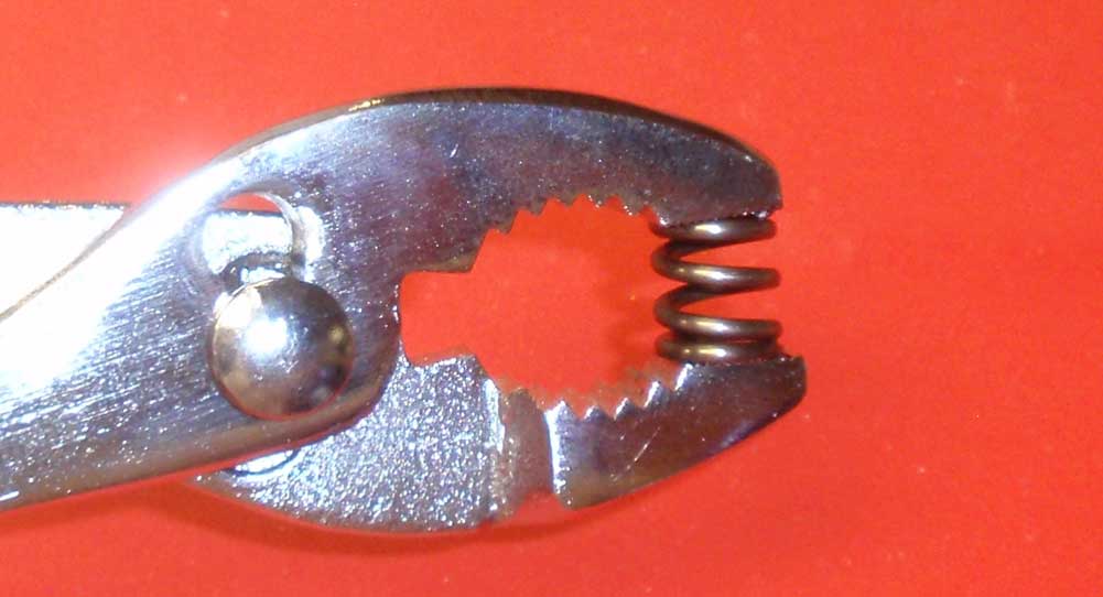
Pre-compress the slipper spring. Give it a couple good squeezes to give it a set.
Step 18
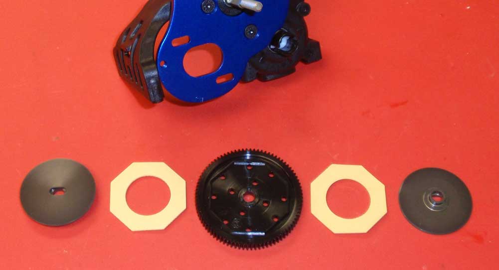
We’ve laid out the V2 slipper parts in order of assembly – slipper hub, slipper pad, 84T spur gear and the other slipper pad and hub. Make sure the slipper pads key to the grooves in the spur gear.
Step 19
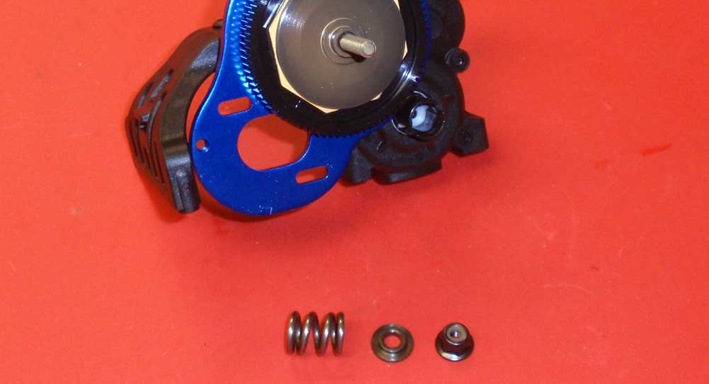
Once the slipper is attached, slide the pre-compressed spring onto the shaft followed by the spring retainer and M4 locknut. The flanged end of the spring retainer should face the spring.
Step 20
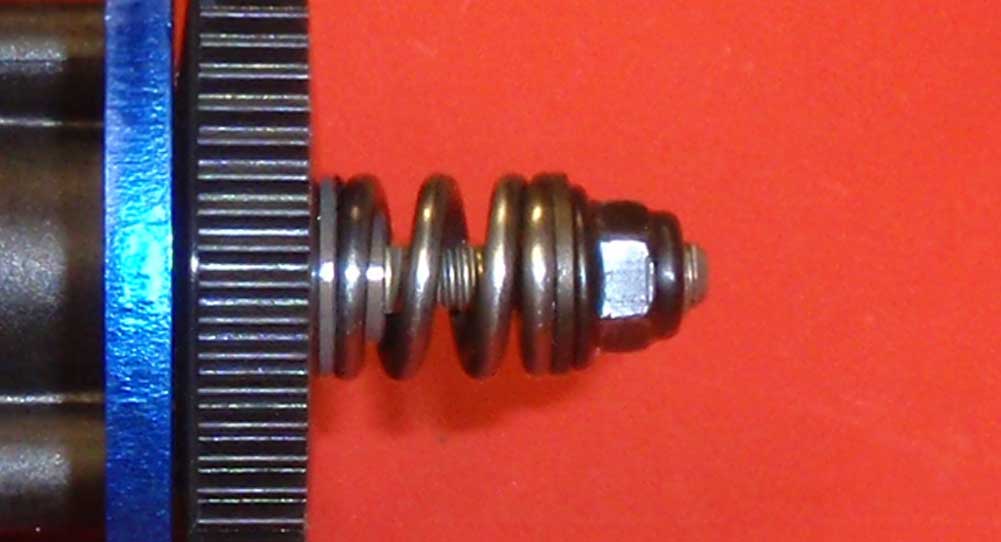
Tighten the M4 locknut until about 1mm of shaft is sticking through it. This is a starting setting and might need adjustment during your first run.
Step 21
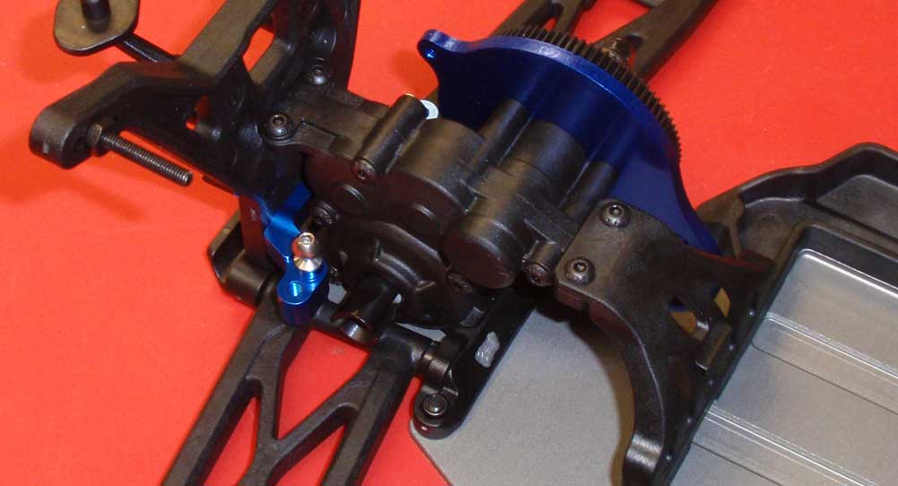
Set the transmission assembly into the truck and attach. I found it easiest to start the 2 18mm screws to key the transmission into place, then install the 2 10mm BHCS screws up top. That made it easier to install the 4 10mm screws from the bottom.
Excellent job on the transmission. Give it a good spin to make sure everything is operating freely. Next up – the rest of the rear suspension.
Team Associated T5M Online Build – Part 5
After installing the transmission, we’re headed back to the rear suspension of the Team Associated T5M to finish it off. A few cool features include the rear hub inserts that allow more adjustment just by changing mounting plates and a full set of CVA drive bones. On with the show.
Build Notes:
• The CVA build requires the use of black grease so you might need a few clean rags for this step as well.
• Pay special attention to the rear hubs when assembly. There is a left and a right side and could be easily swapped without noticing.
Step 1
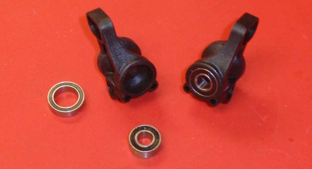
Let’s start by pressing a 6×13 bearing into the front and a 10×15 bearing into the rear of both hubs. As you might notice, the hubs do look different. They are directional so you’ll need to make sure they are assembled on the correct side of the car. The one on the left is for the left side of the truck, the one on the right for the right side.
Step 2
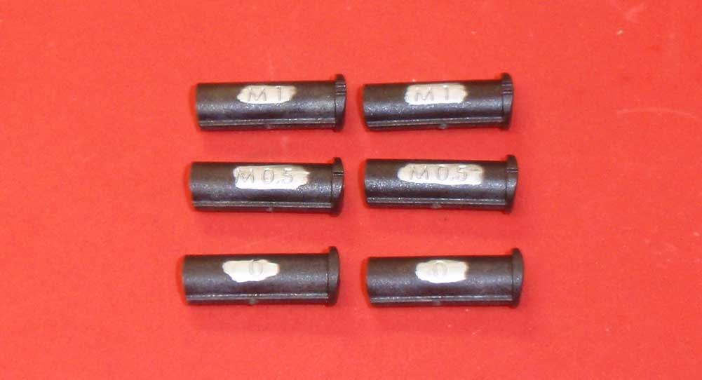
Inserts are also used here to control outboard rear toe of the car. AE has supplied 3 toe inserts; a M1 (or 1°), M0.5 (or .5°) and a 0 (or 0°). We’ll be using the 0° hub per the manual. Again, a silver Sharpie was used to make things easier to read.
Step 3
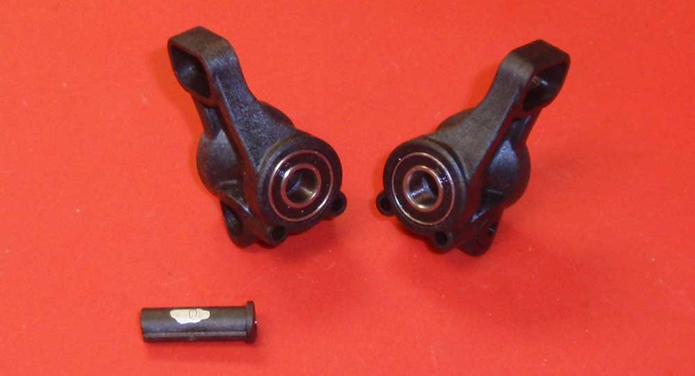
Slip the toe insert into the rear hub. It can only be inserted one way so don’t worry about placing it in backwards.
Step 4
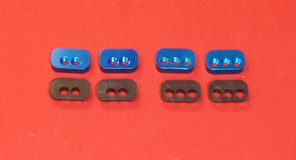
We’ve lined out the rear hub inserts; 2 with 3 holes, 2 with 2 holes. The ones with 2 holes are ‘in between’ holes to the ones with 3. They can be installed with the holes to the top or bottom, allowing even more adjustment. We’ll be using the B insert (or 2 hole insert) with the holes up.
Step 5
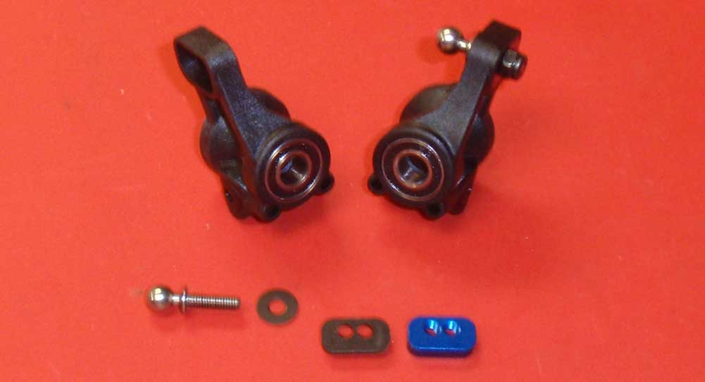
Press the plastic and blue aluminum hub link inserts into the rear hub, making sure both hole-sets are up. Insert the heavy duty ballstud through 8mm washer and into the B hole (insert funny joke here) or outside hole. A drop of threadlocker will help keep the ballstud from coming out.
Step 6
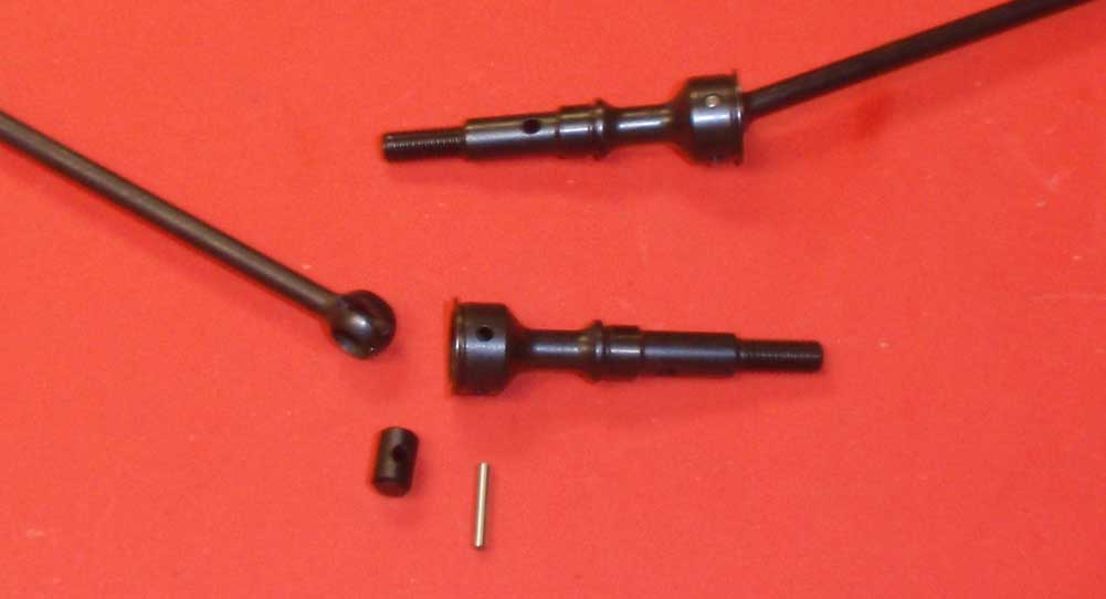
Assemble 2 CVA drive axles. Use a small amount of black grease on the barrel during assembly.
Step 7
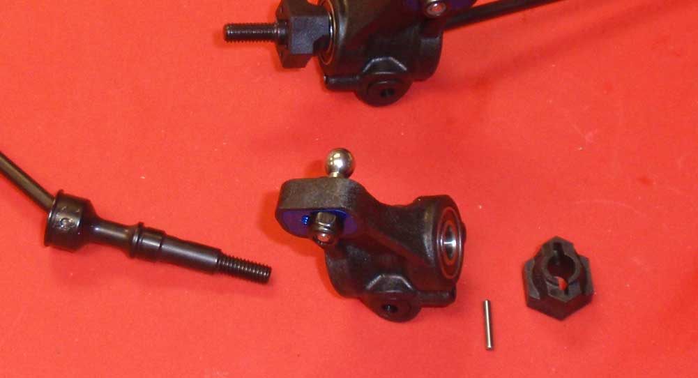
Slide an assembled CVA through the rear hub assembly. Insert the CVA wheel pin followed by the rear wheel hex. Make sure you key the slot in the hex to the wheel pin.
Step 8
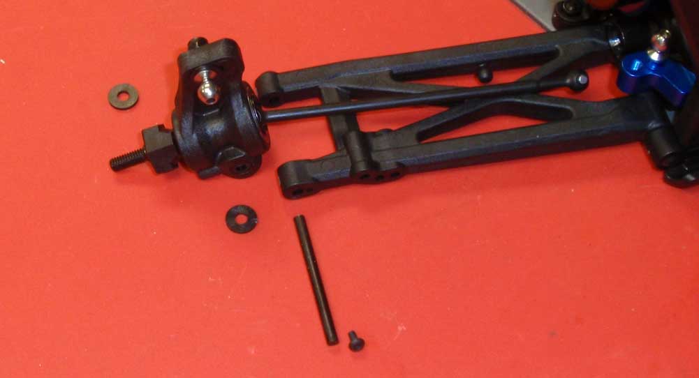
Before the next step, pay close attention to the orientation of the rear hubs. The ballstud should be facing the rear of the T5M. Slide the hinge pin though the arm, a rear hub spacer, the rear hub and another rear hub spacer. Secure with the 4mm screw.
Step 9
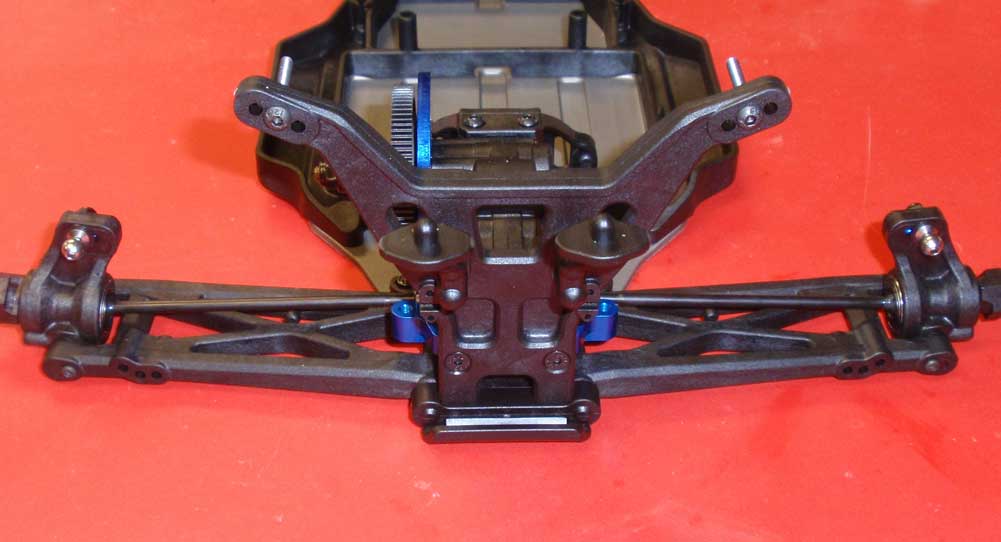
Swing the hubs up and key the CVA bones to the diff outdrives.
Step 10
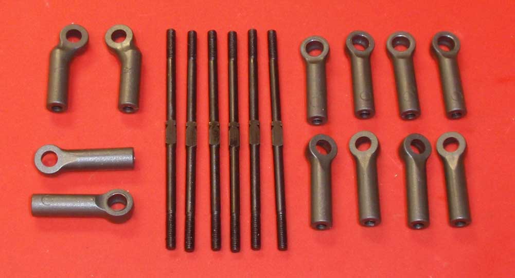
Take a quick inventory of the turnbuckle pieces. The first thing you’ll notice is that all the turnbuckles are the same length! You’ll also notice that they are not blue titanium … that’s a bummer.
Step 11
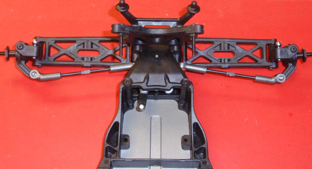
Build the steering links per the manual (the lengths here are a good starting point). Pay special attention to the ballcups themselves as well as the ‘notch’ on the turnbuckle. After assembling 2, pop them into place.
Step 12

Do the same thing with the front camber links. The lengths here are good as well.
Step 13
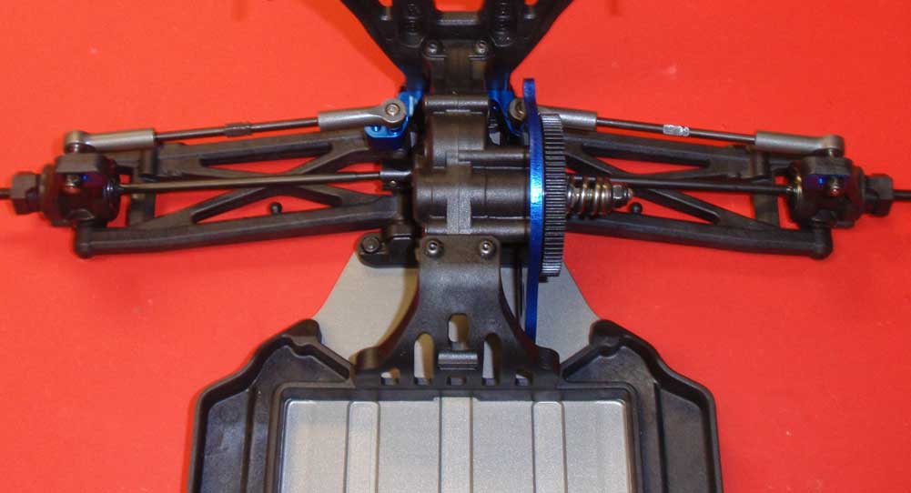
Build a pair of rear camber links again paying close attention to the ‘notch’ in the turnbuckle. The lengths are good here. Before popping them on, make sure the drive bones are keyed to the diff outdrives.
Give everything a spin and work those arms up and down to make sure there is no binding in the drivetrain or suspension. Booyah! Great job!
Team Associated T5M Online Build – Part 6
Team Associated’s T5M comes with their awesome Factory Team V2, Big Bore shocks. Featuring 12mm bodies and healthy 3mm shafts, these shocks are some of the best in the industry.
Build Notes:
• Shock building is messy so make sure you not only have clean up rags, but also a something down on the table first in case any shock fluid spills (and most likely it will).
Step 1
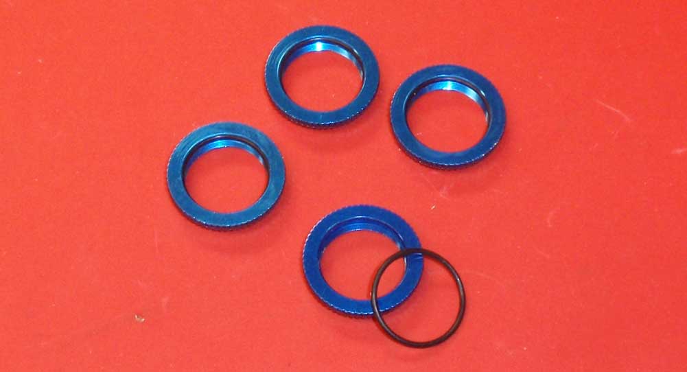
If you’ve followed along with any of our other builds, you’ll notice that we always assemble the threaded collars first. This is because, once you get shock fluid on the o-rings, they can be a PITA to slip into the collars. Trust us when we say you want to do this first … always.
Step 2
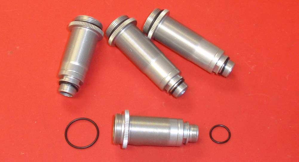
We’ll go ahead and prep the rest of the parts as well. Slip a large o-ring over the top of the shock body and a small one over the bottom.
Step 3
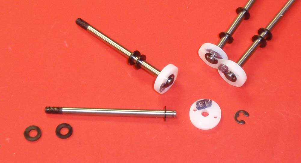
Assemble 4 shock shafts. Note that the front shafts are shorter than the rears, so make sure you put the 1.6 pistons on the short shafts and the 1.7 pistons on the longer shafts. Add 2 .030 nylon spacers to each shaft as shown. I like to color the tops of the pistons (where the numbers are) with a black Sharpie to help me easily identify them. Yes, I like my Sharpies.
Step 4
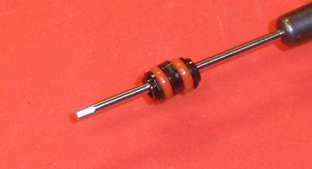
I had a little difficulty getting the seal section built without an o-ring or spacer being dumb, so I tried this little method to get it all installed at the same time. I just applied a small amount of shock fluid to the assembly and it slipped right it without a hitch. Make sure the leading hat bushing’s lip faces INTO the shock and the final hat bushing’s lip faces into the bottom cap.
Step 5
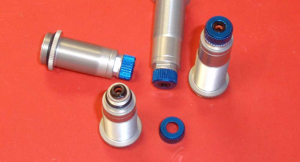
Install the bottom cap, being careful that the hat bushing seats correctly into the cap.
Step 6
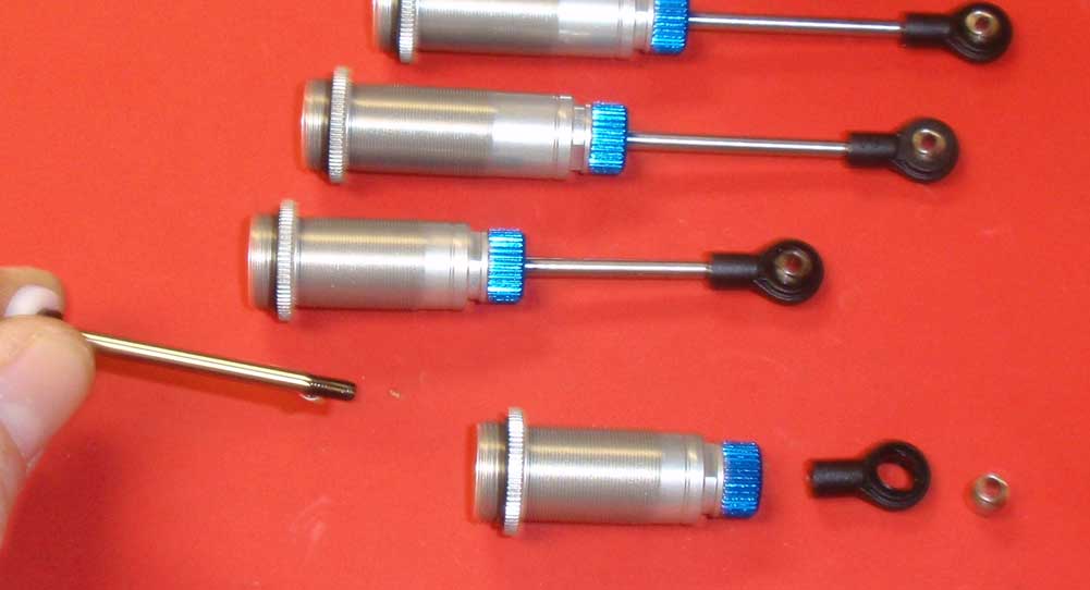
Place a drop of shock fluid onto the threads of the shaft and slide it through the assembled shock. Once through, install the shock eyelet and pivot ball. Plunge the shaft a few times to make sure the seals get coated with oil.
Step 7
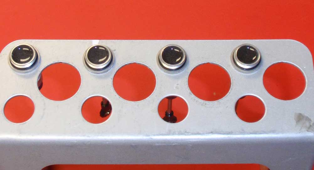
Before filling the shocks with oil, make sure you have a suitable shock stand. I have a few different ones I use and added the links at the bottom. Fill the shocks with fluid (kit 35wt is a good start) almost all the way to the top. Plunge the shaft a few times to release any air bubbles from below the piston and place in your shock stand.
Step 8
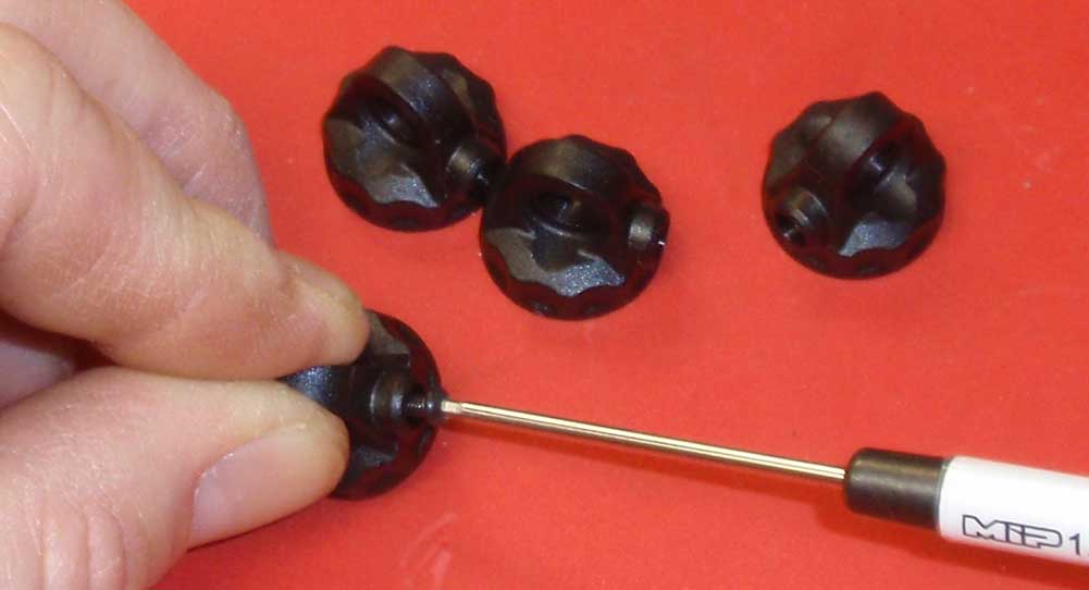
While the bubbles are rising out of the shocks, we’ll take this time to prep the shock caps. Start by a 4mm screw into each hole in the cap, then remove it.
Step 9
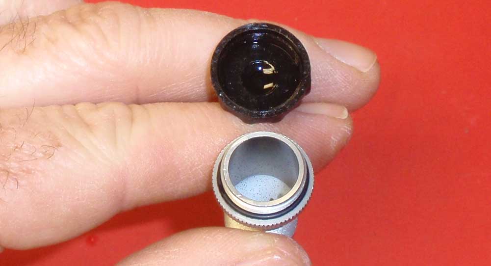
Grab a shock from the stand and add more fluid until the fluid is flush with the top of the shock body. Place a single drop of fluid in the cap, then flip the cap onto the body and tighten down keeping the hole in the cap pointing up. Careful not to cross-thread the cap.
Step 10
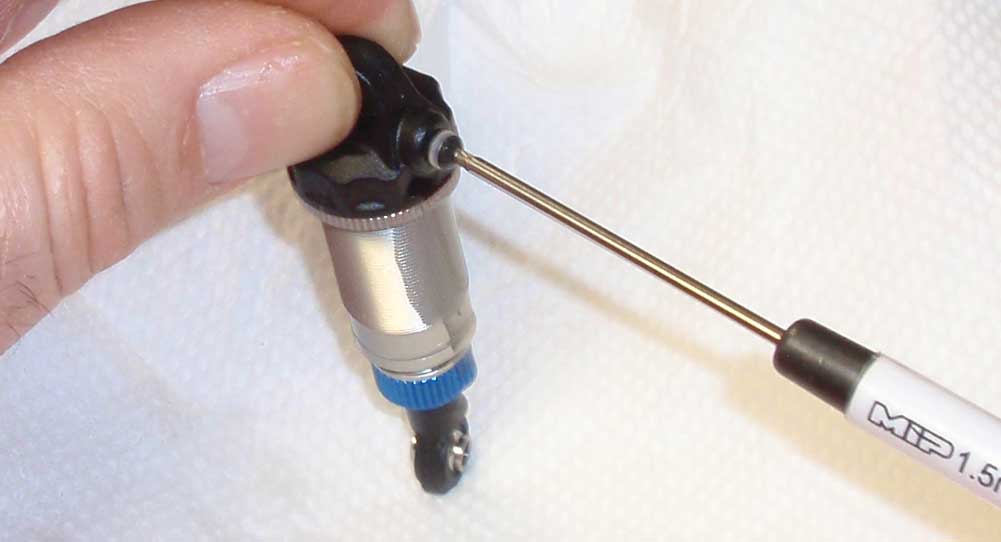
While slowly pressing down on the shock as shown (hopefully you’re doing it on a paper towel!), you’ll see fluid start to come out of the hole in the cap. Once the shock shaft has bottomed out, insert the 4mm screw. AE includes small white washers in the shock bag but doesn’t show them in the manual; I like to use them since it appears to make a better seal.
Step 11
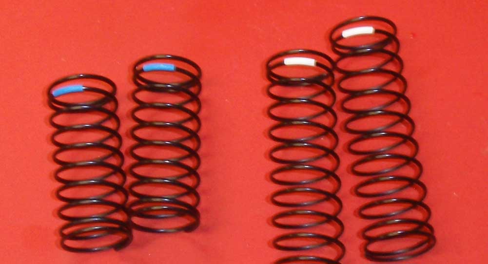
The T5M comes with 3.6lb front springs (blue) and 2.1lb rear springs (white). Slip the colored shrinkwrap onto the shock and heat it to keep it in place. A hairdryer, lighter or even a soldering iron will help with this … just don’t burn yourself!
Step 12
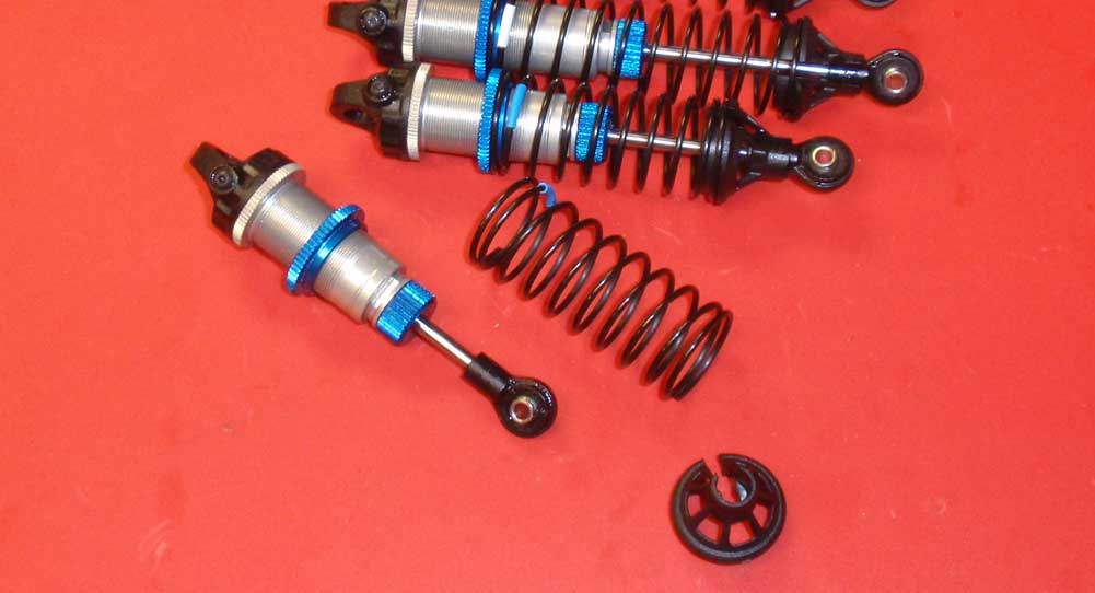
Thread the collar onto the shock followed by the appropriate spring (blue on the front, white on the rear). AE also includes multiple height shock spring cups. Grab the 9mm offset ones (tall ones) and snap those into place under the shocks.
Step 13
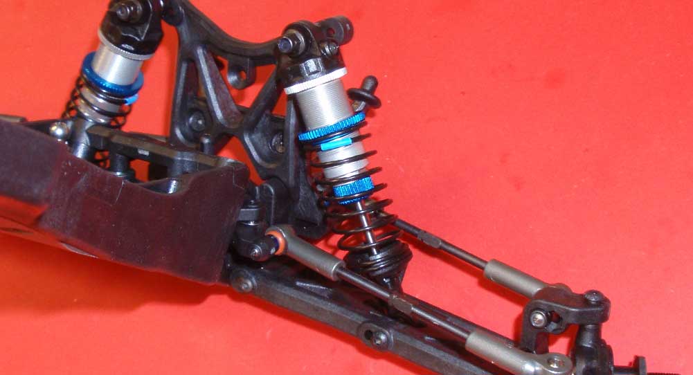
Set the shorter, front shocks into place and secure the tops with the M3 lockut. Secure the bottoms in the outer hole with the 22mm screw.
Step 14
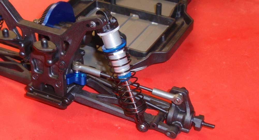
Same goes for the rear shocks; secure the tops with the M3 locknut and the bottoms (in the inside hole) with the 12mm screws.
Looks good, right? Take a moment and compress the shocks a few times to make sure all is silky smooth.
Team Associated T5M Online Build – Part 7
A truck as bad ass as the T5M needs to have some bad ass running gear. For this, we’ll be using the following stuff:
• Reedy RS1508 Digital HV Servo
• Reedy Blackbox 410R Competition Brushless ESC
• Reedy Sonic 540 Mach 2 7.0T Brushless Motor
• Reedy 5800mAh 65C 7.4V LiPo Battery
• Futaba 4PX Transmitter
• Proline ION T 2.2″ Truck Tires
All of this is nice, high-end that will compliment the T5M perfectly. Let’s get to the install.
Build Notes:
• The first thing you might notice is the top-down servo install instead of mounting it from the bottom. Since servos come in many different shapes and sizes, this could cause an issue at some point. Thankfully the Reedy servo dropped in without a fuss.
• If you haven’t purchased a battery pack yet (or have some and not sure if they’ll work), you’ll be happy to hear that the T5M accepts a few different pack configurations including saddle, shorty and brick packs.
Step 1
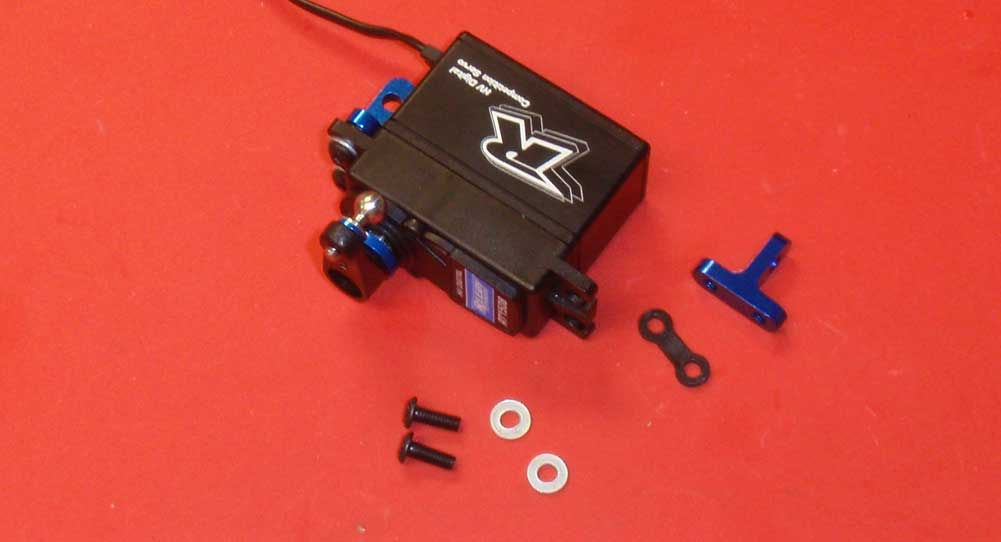
Let’s start this build by prepping the servo for installation. Choose the servo horn that works with your servo (Airtronics, Futaba, Hitec or JR) and attach the blue servo ring and heavy duty ballstud. The servo mounts are a new design (unless you’ve had a B5 or B5M before), but they attach in much the same way. The instructions say to use a ‘gold’ washer, mine were silver.
Step 2
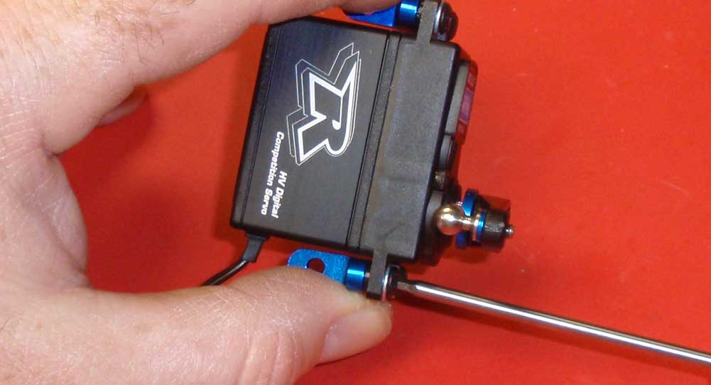
I pinched the mounts tight to the servo before tightening down the screws. This made them equal on both sides and easier to install into the truck.
Step 3
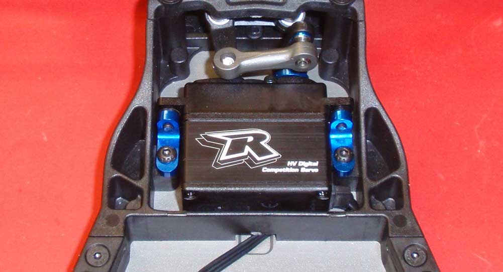
Before lowering the servo down into its pocket, feed the servo lead through the opening in the plastic cross brace. Secure the servo with the pair of 8mm screws. Also new is the one-piece drag link, making this part of the build a no-brainer. Thank you AE, been wanting this for a long time.
Step 4
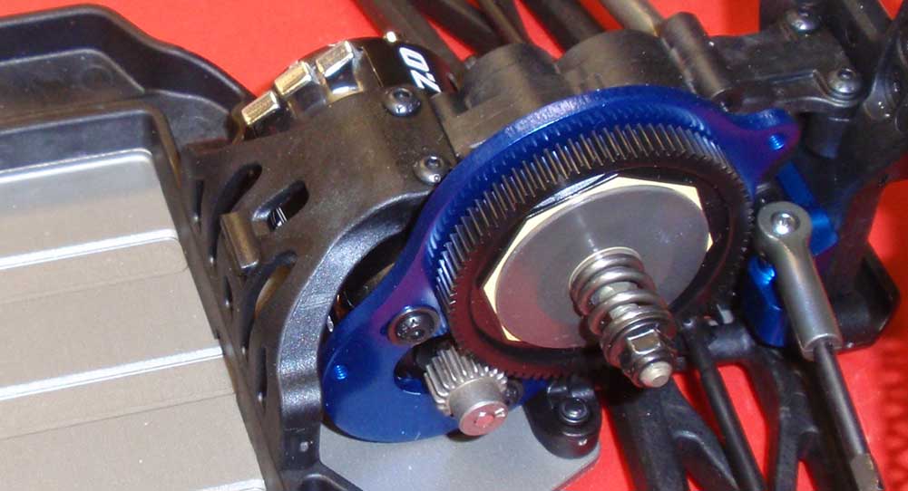
Align and attach the motor to the motor plate, but don’t tighten the screws just yet. Check the mounting tabs on the motor to make sure they are not interferring with anything. Now install the pinion, set the gear mesh and tighten everything down.
Step 5
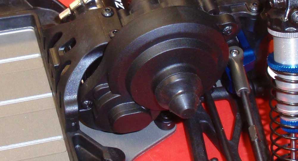
Attach the gear cover.
Step 6
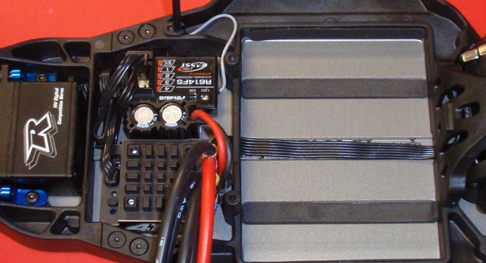
The section right behind the servo is for the receiver and ESC. You might want to do some test fitting to see how you want things to go, but remember that the battery strap thumbscrews attach to the back wall of this compartment. You might even build and install that prior to mounting the electronics. Once you get that situated, attach the sensor wire to the ESC and feed it down the center channel of the T5M. yes, that channel runs right to the motor, keeping the sensor wire out of the way and well protected. At this time you can also install the antenna system and foam pads under the battery compartment.
Step 7
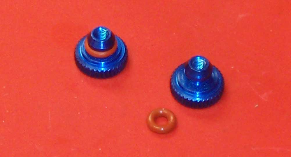
Build 2 of the battery thumbscrews.
Step 8
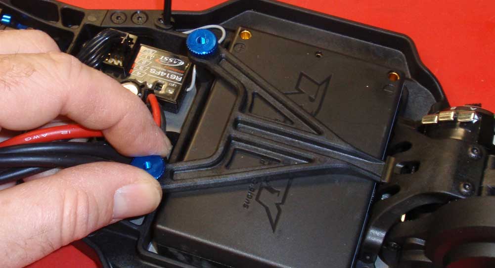
We dropped our macho brick pack into the try and installed the battery strap and thumbscrews.
Step 9
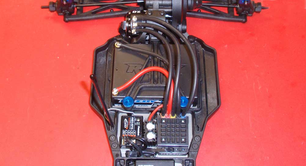
Solder the wires to the motor and install the plugs for the battery. At this time you might want to turn everything on to make sure it’s all working before moving to the final step.
Awesome job. If you’re anything like us, we’re ready to just slap some tires and any ol’ body on it and hit the track! This thing looks great! Only one more step to get before it’s time to let it loose!
Team Associated T5M Online Build – Part 8
The final step in the Team Associated T5M build is the body, wheels and tires. It does come with a cool Proline body but not with tires, which isn’t all the odd. What IS odd is that it doesn’t come with wheels either.
Build Notes:
• The body is clear so you’ll need to get that painted before you run out and drive this truck. Ok, maybe not, but it is suggested that you get it painted before you run this truck.
• You’ll be gluing the tires to the wheels with CA glue. Be very careful around this stuff; it has no qualms about gluing your fingers together!
Step 1
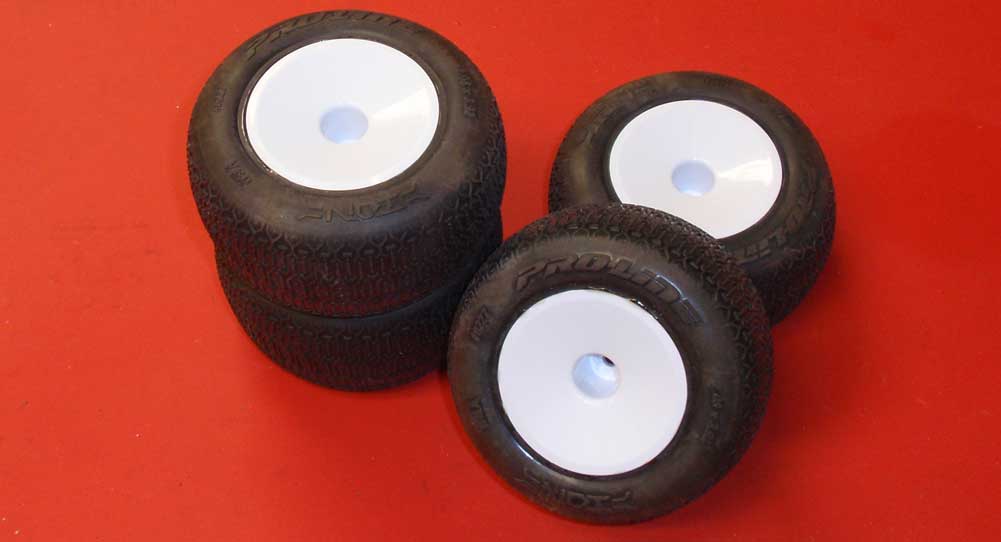
The first step is to mount your tires. I would suggest finding out what tires work best at your local track and get those. While you’re there, you might as well pick up wheels too.
Step 2
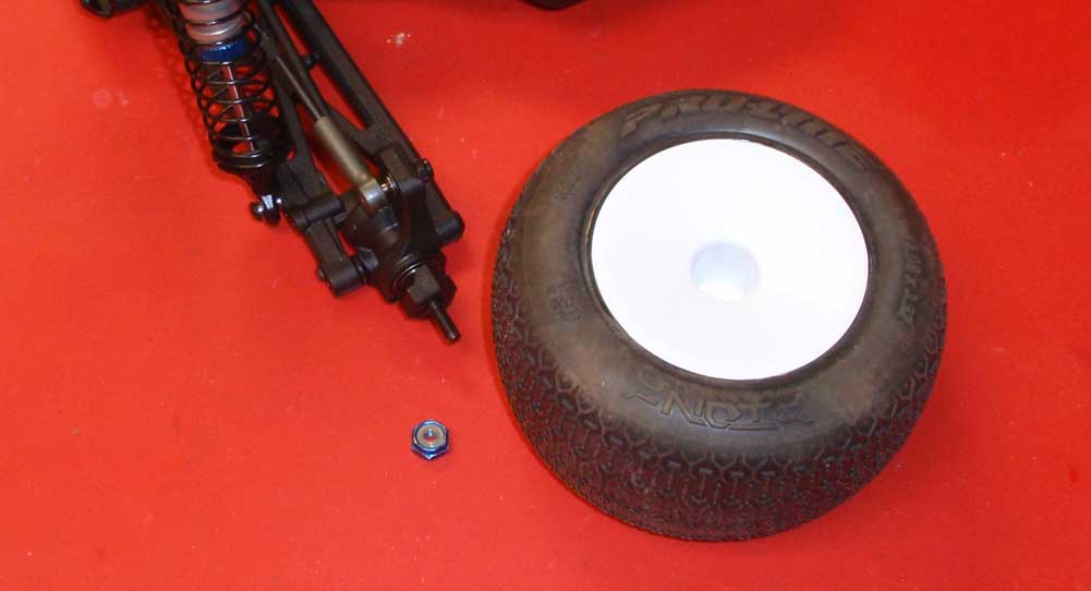
The T5M uses the same hex on all 4 corners, making it easy to install your tires.
Step 3
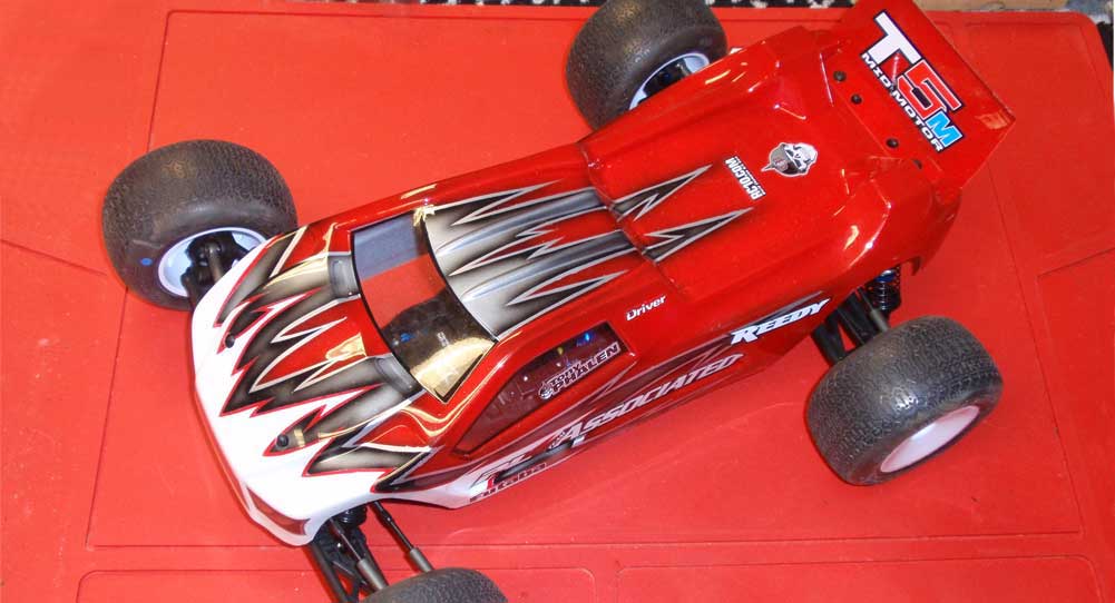
Paint, trim and mount the body. I suck at painting, so I had Larry Genova over at Kustom RC Graphics squirt the beautiful paint. This guy does an amazing job … it always comes out looking so professional!
And there you have it … the T5M ready to rock! Time to charge your batteries and get this Stadium Truck out for some high-flying action.
Thanks to everyone who followed this build.

