The Build – Part 5
Part 2 of the Team Associated B6D rear suspension build has us attaching the gearbox and assembling the rear hubs. The rear hubs still use inserts to control rear toe and camber link locations. I’m also really liking the new rear ballstud mount.
 In Step 4, you will need to press the aluminum hub link nut and plastic link insert into the rear hub. The aluminum part only fits in one side of the hub, so don’t worry about getting it mixed up.
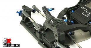
The rear ballstud mount now gets sandwiched between the gearbox brace and gearbox … a much better design in my opinion. Start by inserting the 8mm ballstuds into the center hole, using one 1mm and one 2mm shim under each ballstud.

Press the aluminum ballstud mount onto the gearbox brace, then set the gearbox into place. Secure with the two 14mm screws up top and the 10mm and 12mm screws underneath.

Like the front, the rear hubs use inserts with tabs to alter the performance. We’ll be using the 0/3 block with the tab up (I’ve highlighted the numbers so you can see where they are). Press a 0/3 insert (tab up) into each rear hub.

Press the aluminum hub link nut and plastic link insert into the rear hub with the 3-holes to the top (it has 5 holes in it). Slide the 3×8 washer over the 10mm ballstud and feed it through the hub using the top/center hole. Secure it with the M3 locknut. Now press a 6×13 and 10×15 bearing into each hub.

Assemble two CVA drive bones. Slide the coupler into the ball at the end of the bone, then slide that assembly into the CVA axle. Line up the holes and insert the hex pin through the axle and coupler.

Feed the axle assembly through the rear hub assembly, making sure the pin stays centered in the CVA. Once through, slide another hex pin through the axle, then slide the 7.0mm aluminum wheel hex over the hex pin. Use the 1.6x5mm pin to clamp the hex.
Slide the outer hinge pin though the rear suspension arm, though one rear hub spacer, the assembly rear hub and the second hub spacer. Secure the hinge pin with the M2x4mm screw. Complete both sides.
Rear suspension is now done … time to build the turnbuckles and shocks!
Team Associated B6D Build – Part 1 – Steering – Servo
Team Associated B6D Build – Part 2 – Front Suspension
Team Associated B6D Build – Part 3 – Rear Suspension Part 1
Team Associated B6D Build – Part 4 – Gearbox
Team Associated B6D Build – Part 5 – Rear Suspension Part 2
Team Associated B6D Build – Part 6 – Turnbuckles – Shock Towers
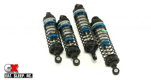
Team Associated B6D Build – Part 7 – Shocks
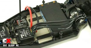
Team Associated B6D Build – Part 8 – Electronics